CN215682060U - Efficient elevator main machine - Google Patents
Efficient elevator main machine Download PDFInfo
- Publication number
- CN215682060U CN215682060U CN202121333921.1U CN202121333921U CN215682060U CN 215682060 U CN215682060 U CN 215682060U CN 202121333921 U CN202121333921 U CN 202121333921U CN 215682060 U CN215682060 U CN 215682060U
- Authority
- CN
- China
- Prior art keywords
- motor
- fixedly connected
- stator
- cooling
- heat dissipation
- Prior art date
- Legal status (The legal status is an assumption and is not a legal conclusion. Google has not performed a legal analysis and makes no representation as to the accuracy of the status listed.)
- Active
Links
Images


Abstract
The utility model relates to the technical field of motors, in particular to a high-efficiency elevator host machine which comprises a heat dissipation protection cover device, a motor device and a cooling device, wherein the heat dissipation protection cover device is made of graphene materials and is tightly attached to a motor shell; a cooling device is added in the motor device and performs liquid cooling on the stator, so that the temperature of the stator is reduced, the performance of the motor is improved, and the loss is reduced; the stator in the motor device is made of cast copper, so that the electrification performance can be greatly improved, the magnetic loss of the motor can be reduced, and the efficiency is greatly improved. The utility model has the advantages of good heat dissipation effect, strong rotor electrification magnetism, reduced magnetic loss, improved efficiency and improved motor torque.
Description
Technical Field
The utility model relates to the technical field of motors, in particular to a high-efficiency elevator main machine.
Background
An electric Motor (Motor) is a device that converts electrical energy into mechanical energy. The electromagnetic power generator utilizes an electrified coil (namely a stator winding) to generate a rotating magnetic field and acts on a rotor (such as a squirrel-cage closed aluminum frame) to form magnetoelectric power rotating torque. The motors are divided into direct current motors and alternating current motors according to different power supplies, most of the motors in the power system are alternating current motors, and can be synchronous motors or asynchronous motors (the rotating speed of a stator magnetic field of the motor is different from the rotating speed of a rotor to keep synchronous speed). The motor mainly comprises a stator and a rotor, and the direction of the forced movement of the electrified conducting wire in a magnetic field is related to the current direction and the direction of a magnetic induction line (magnetic field direction). The working principle of the motor is that the magnetic field exerts force on current to rotate the motor.
The motor is very convenient to use and control, has the capabilities of self-starting, accelerating, braking, reversing, stopping and the like, and can meet various operation requirements; the motor has high working efficiency, no smoke and smell, no environmental pollution and less noise. Due to a series of advantages, the method is widely applied to industrial and agricultural production, transportation, national defense, commercial and household appliances, medical and electrical equipment and the like. Therefore, a motor for an elevator appears on the market, and for example, chinese patent CN201721712809.2 discloses a high-efficiency motor for an escalator, which comprises: the motor comprises a base, an upper end cover, a lower end cover, a stator, a rotor, a rotating shaft, a heat dissipation fan, a junction box, a heat dissipation fin and a brake disc, wherein the upper end cover is installed at the upper end of the base, the lower end cover is installed at the lower end of the base, the junction box is fixedly installed at the top of the base, the heat dissipation fin is fixedly installed on the outer peripheral wall of the base, the stator is fixedly installed on the inner peripheral wall of the base, the rotating shaft is installed in the center inside the base and penetrates through the upper end and the lower end of the base, the rotor is sleeved on the rotating shaft and is arranged opposite to the stator, the heat dissipation fan is installed inside the base and is close to one side of the upper end cover, the brake disc is installed at the lower side of the heat dissipation fan and is fixedly connected with the rotating shaft, the stator is formed by vertically stacking a plurality of stator punching sheets, and the shape of each stator punching sheet is octagonal, stator pins are arranged on the inner side of each edge, the cambered surfaces on the inner sides of the stator pins enclose a circular space, winding slots are formed between adjacent stator pins, stator windings are wound on the stator pins, vent holes and mounting holes are formed in every two edges of the stator punching sheet, the mounting holes are symmetrically arranged on two sides of the vent holes, and bolts penetrate through the mounting holes to fixedly connect the stator punching sheets which are stacked up and down; the rotor is stacked from top to bottom by a plurality of rotor monomers and is constituteed, every the rotor monomer comprises substrate and a plurality of rotor punching, the shape of substrate is circular, open at the substrate center has the shaft hole, the shape of rotor punching is fan-shaped, the rotor punching is along the even fixed mounting of substrate circumference, and the cambered surface in every rotor punching outside flushes with the substrate outer fringe, every be equipped with oval magnetic wire casing on the rotor punching, and the winding has rotor winding in the magnetic wire casing, connects through the connecting piece between two adjacent rotor punching along substrate circumference, connects the installation through dovetail and dovetail between two adjacent rotor punching along the substrate axial. Although the motor described above solves some of the problems, it is still insufficient in terms of heat dissipation, and the energization magnetism of the rotor is low, affecting the efficiency of the motor.
There is therefore a need for an efficient elevator machine that solves the above problems.
SUMMERY OF THE UTILITY MODEL
In order to solve the problems, the utility model aims to provide a high-efficiency elevator main machine.A heat dissipation protective cover device is additionally arranged on the outer surface of a motor device, the device adopts the graphene of the latest technology, and the heat on the surface of a motor shell is dissipated by the graphene, so that the temperature of a motor is further reduced, and the motor efficiency is improved. The utility model has the advantages of good heat dissipation effect, strong rotor electrification magnetism, reduced magnetic loss, improved efficiency and improved motor torque.
The technical scheme adopted by the utility model for solving the technical problems is as follows: the utility model provides a high-efficient elevator host computer, includes motor device and cooling device, be equipped with heat dissipation safety cover device on the motor device, heat dissipation safety cover device and motor device are fixed connection, and cooling device sets up in the motor device, and cooling device and motor device are fixed connection.
Further, heat dissipation safety cover device includes the sound-proof housing device, is equipped with the steel wire on the sound-proof housing device and separates the net, and the steel wire separates the net and is fixed connection with the sound-proof housing device, and sound-proof housing device lower extreme is equipped with the heat dissipation guard shield, and heat dissipation guard shield both sides are equipped with connecting plate A, and connecting plate A is fixed connection with the heat dissipation guard shield, is equipped with bolt assembly A on the connecting plate A, and bolt assembly A is threaded connection with connecting plate A, and the heat dissipation guard shield is fixed connection with the motor device.
Further, the motor device includes the motor structure, the motor structure lower extreme is equipped with the fin, the fin is fixed connection with the motor structure, motor structure one side is equipped with the terminal box, be equipped with screw subassembly B on the terminal box, the terminal box passes through screw subassembly B fixed connection with the motor structure, the terminal box both sides are equipped with wiring mouth A and wiring mouth B, wiring mouth A and wiring mouth B are fixed connection with the terminal box, the motor structure both sides are equipped with rings device, rings device and motor structure are threaded connection, the motor structure lower extreme is equipped with connector A, be equipped with screw subassembly C on the connector A, connector A one end passes through screw subassembly C fixed connection with the motor structure, the connector A other end is equipped with the ring flange, the ring flange is fixed connection with connector A, be equipped with the motor shaft in the motor structure, the motor shaft is connected for the drive with the motor structure, the ring flange is fixed connection with the heat dissipation guard shield.
Further, the motor structure includes motor casing and fan housing, be equipped with the flabellum in the fan housing, the flabellum is fixed connection with the one end of motor shaft, motor casing one end is equipped with the end cover, the end cover passes through screw subassembly D fixed connection with motor casing, fan housing passes through locking structure fixed connection with motor casing, fan housing one end is equipped with the fan casing, the fan casing is fixed connection with the fan housing, the one end of motor shaft is equipped with non-drive bearing, non-drive bearing is connected for rotating with the motor shaft, the other end of motor shaft is equipped with drive bearing, drive bearing is connected for rotating with the motor shaft, motor casing passes through E fixed connection with the ring flange, be equipped with screw device on the motor shaft, rotor device is connected for the drive with the motor shaft, the rotor device outside is equipped with stator device, stator device is fixed connection with motor casing.
Further, the stator device comprises a stator body, wherein a mounting groove is formed in the stator body, a hole A is formed in the stator body, a cooling pipe is arranged in the hole A, the cooling pipe is fixedly connected with the stator body, a stator groove is formed in the stator body, the stator groove is fixedly connected with the stator body, a stator lead is arranged on the stator groove, the stator lead is fixedly connected with the stator groove, protective covers are arranged at two ends of the stator body, the protective covers are fixedly connected with the stator body, the stator body is fixedly connected with a motor shell, and the cooling pipe is fixedly connected with the cooling device.
Furthermore, the rotor device comprises a rotor punching sheet, end rings are arranged at two ends of the rotor punching sheet, the end rings are fixedly connected with the rotor punching sheet, and the rotor punching sheet is fixedly connected with a motor shaft.
Furthermore, the rotor punching sheet is made of copper and adopts a copper casting process.
Further, cooling device includes the cooler bin, the cooler bin lower extreme is equipped with mounting panel B, mounting panel B is fixed connection with the cooler bin, be equipped with screw subassembly F on the mounting panel B, mounting panel B passes through screw subassembly F fixed connection with the ring flange, the cooler bin upper end is equipped with the interface, the interface is fixed connection with the cooler bin, interface one end is equipped with the connecting pipe, connecting pipe one end is fixed connection with the interface, the connecting pipe other end is fixed connection with the cooling tube, the interface other end is equipped with the poling, poling one end is fixed connection with the interface, the inside pump body that is equipped with of cooler bin, the pump body is fixed connection with the cooler bin, the poling other end is fixed connection with the pump body.
The utility model has the advantages that: the utility model provides a high-efficiency elevator host, which comprises a heat dissipation protection cover device, a motor device and a cooling device, wherein the heat dissipation protection cover device is made of graphene materials and is tightly attached to a motor shell; a cooling device is added in the motor device and performs liquid cooling on the stator, so that the temperature of the stator is reduced, the performance of the motor is improved, and the loss is reduced; the stator in the motor device is made of cast copper, so that the electrification performance can be greatly improved, the magnetic loss of the motor can be reduced, and the efficiency is greatly improved. The utility model has the advantages of good heat dissipation effect, strong rotor electrification magnetism, reduced magnetic loss, improved efficiency and improved motor torque.
Drawings
In order to more clearly illustrate the embodiments of the present invention or the technical solutions in the prior art, the drawings used in the description of the embodiments or the prior art will be briefly described below, and it is obvious that the drawings in the following description are some embodiments of the present invention, and other drawings can be obtained by those skilled in the art without creative efforts.
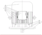
FIG. 1 is a schematic perspective view of the present invention;
FIG. 2 is a schematic view of a heat dissipation protective cover device according to the present invention;
FIG. 3 is a schematic view of the motor apparatus of the present invention;
FIG. 4 is an internal schematic view of the motor apparatus of the present invention;
FIG. 5 is a schematic view of a stator of the present invention;
FIG. 6 is a schematic view of a rotor of the present invention;
FIG. 7 is a schematic view of a cooling apparatus of the present invention;
wherein: 1. a heat dissipation protective cover device; 11. a steel wire separation net; 12. a sound-proof housing device; 13. a connecting plate A; 14. a bolt assembly A; 15. a heat-dissipating shield; 2. a motor device; 21. a motor structure; 211. A fan housing; 212. a fan blade; 213. a non-drive bearing; 214. an end cap; 215. a screw assembly D; 216. A locking structure; 217. a stator arrangement; 2171. a protective cover; 2172. a stator lead; 2173. a stator slot; 2174. a cooling tube; 2175. a hole A; 2176; mounting grooves; 2177. a stator body; 218. a rotor arrangement; 2181. rotor punching sheets; 2182. an end ring; 219. a drive bearing; 2110. a screw assembly E; 2111. a motor housing; 2112. a fan housing; 22. a screw assembly B; 23. a junction box; 24. a wiring port A; 25. a wiring port B; 26. a heat sink; 27. a ring device; 28. a screw assembly C; 29. a linker A; 210. a motor shaft; 2113. a flange plate; 3. a cooling device; 31. a connecting pipe; 32. an interface; 33. guiding a pipe; 34. cooling liquid; 35. a pump body; 36. a screw assembly F; 37. mounting a plate B; 38. And a cooling tank.
Detailed Description
The technical solutions of the present invention will be described clearly and completely with reference to the accompanying drawings, and it should be understood that the described embodiments are some, but not all embodiments of the present invention. All other embodiments, which can be derived by a person skilled in the art from the embodiments given herein without making any creative effort, shall fall within the protection scope of the present invention.
In the description of the present invention, it should be noted that unless otherwise explicitly specified or limited, the terms "center", "upper", "lower", "left", "right", "vertical", "horizontal", "inner", "outer", and the like indicate orientations or positional relationships based on those shown in the drawings, and are only for convenience of description and simplicity of description, and do not indicate or imply that the referred device or element must have a specific orientation, be constructed in a specific orientation, and be operated, and thus, should not be construed as limiting the present invention. Furthermore, the terms "first," "second," and "third" are used for descriptive purposes only and are not to be construed as indicating or implying relative importance, and the terms "mounted," "connected," and "connected" are to be construed broadly and may be, for example, fixedly connected, detachably connected, or integrally connected; can be mechanically or electrically connected; they may be connected directly or indirectly through intervening media, or they may be interconnected between two elements. The specific meanings of the above terms in the present invention can be understood in specific cases to those skilled in the art.
Example 1:
fig. 1 is a schematic perspective view of the efficient elevator shown in fig. 1, which includes a motor device 2 and a cooling device 3, wherein the motor device 2 is provided with a heat dissipation protective cover device 1, the heat dissipation protective cover device 1 is fixedly connected with the motor device 2, the cooling device 3 is arranged in the motor device 2, and the cooling device 3 is fixedly connected with the motor device 2. According to the arrangement, the heat dissipation protection cover device 1 is made of graphene materials and is tightly attached to the motor device 2, and the motor device 2 is dissipated through good heat dissipation performance of the graphene, so that the efficiency of the motor is improved, and the heat dissipation protection cover device 1 can effectively reduce the noise of the motor during working; the cooling device 3 is added in the motor device 2, and the cooling device 3 cools the internal structure of the motor device 2, thereby improving the performance of the motor.
Example 2:
fig. 2 is a schematic view of a heat dissipation protective cover device of the present invention, and as shown in fig. 2, the heat dissipation protective cover device 1 includes a sound-proof cover device 12, a steel wire mesh 11 is disposed on the sound-proof cover device 12, the steel wire mesh 11 is fixedly connected to the sound-proof cover device 12, a heat dissipation shield 15 is disposed at a lower end of the sound-proof cover device 12, connection plates a13 are disposed at two sides of the heat dissipation shield 15, the connection plates a13 is fixedly connected to the heat dissipation shield 15, a bolt assembly a14 is disposed on the connection plate a13, the bolt assembly a14 is in threaded connection with the connection plate a13, and the heat dissipation shield 15 is fixedly connected to the motor device 2. So set up, noise that sound-proof housing device 12 can effectively reduce motor operation fan and send, and heat dissipation shroud 15 can adopt the good material of heat conductivity to make, for example graphite alkene, closely laminates through graphite alkene and motor housing, can dispel motor housing's heat, improves the radiating efficiency of motor, strengthens the performance of motor.
Example 3:
fig. 3 is a schematic view of a motor apparatus of the present invention, fig. 4 is a schematic view of an inside of the motor apparatus of the present invention, and as shown in fig. 3 and fig. 4, the motor apparatus 2 includes a motor structure 21, a heat sink 26 is disposed at a lower end of the motor structure 21, the heat sink 26 is fixedly connected to the motor structure 21, a terminal box 23 is disposed at one side of the motor structure 21, a screw assembly B22 is disposed on the terminal box 23, the terminal box 23 is fixedly connected to the motor structure 21 through a screw assembly B22, a wiring port a24 and a wiring port B25 are disposed at two sides of the terminal box 23, the wiring port a24 and a wiring port B25 are both fixedly connected to the terminal box 23, a hanging ring device 27 is disposed at two sides of the motor structure 21, the hanging ring device 27 is in threaded connection with the motor structure 21, a connecting body a29 is disposed at a lower end of the motor structure 21, a screw assembly C28 is disposed on the connecting body a29, one end of the connecting body a29 is fixedly connected to the motor structure 21 through a screw assembly C28, the other end of the connector A29 is provided with a flange 2113, the flange 2113 is fixedly connected with the connector A29, a motor shaft 210 is arranged in the motor structure 21, the motor shaft 210 is in driving connection with the motor structure 21, and the flange 2113 is fixedly connected with the heat dissipation shield 15. The motor structure 21 includes a motor housing 2111 and a fan housing 2112, the fan housing 2112 is provided with a fan blade 212, the fan blade 212 is fixedly connected with one end of a motor shaft 210, one end of the motor housing 2111 is provided with an end cover 214, the end cover 214 is fixedly connected with the motor housing 2111 through a screw assembly D215, the fan housing 2112 is fixedly connected with the motor housing 2111 through a locking structure 216, one end of the fan housing 2112 is provided with a fan cover 211, the fan cover 211 is fixedly connected with the fan housing 2112, one end of the motor shaft 210 is provided with a non-driving bearing 213, the non-driving bearing 213 is rotatably connected with the motor shaft 210, the other end of the motor shaft 210 is provided with a driving bearing 219, the driving bearing 219 is rotatably connected with the motor shaft 210, the motor housing 2111 is fixedly connected with a flange 2113 through a screw assembly E2110, the motor shaft 210 is provided with a rotor device 218, the rotor device 218 is drivingly connected with the motor shaft 210, and the outer side of the rotor device 217 is provided with the motor housing 218, stator device 217 is fixedly connected to motor housing 2111. So set up, the motor structure of this structure is small and exquisite, is convenient for maintain and maintain, also is convenient for the handling. Meanwhile, a plurality of groups of wiring ports are arranged on the junction box 23, so that the use under various environments can be met.
Example 4:
fig. 5 is a schematic diagram of a stator of the present invention, fig. 6 is a schematic diagram of a rotor of the present invention, and fig. 5 and fig. 6 illustrate a high-efficiency elevator main machine of the present invention, where the stator device 217 includes a stator body 2177, the stator body 2177 is provided with an installation slot 2176, the stator body 2177 is provided with a hole a2175, the hole a2175 is provided with a cooling tube 2174, the cooling tube 2174 is fixedly connected with the stator body 2177, the stator body 2177 is provided with a stator slot 2173, the stator slot 2173 is fixedly connected with the stator body 2177, the stator slot 2173 is provided with a stator lead 2, the stator lead 2172 is fixedly connected with the stator slot 2173, the two ends of the stator body 2177 are provided with protective covers 2171, the protective covers 1 and the stator body 2177 are fixedly connected, the stator body 2177 is fixedly connected with a motor housing 2111, and the cooling tube 2174 is fixedly connected with the cooling device 3. The rotor device 218 comprises a rotor punching sheet 2181, end rings 2182 are arranged at two ends of the rotor punching sheet 2181, the end rings 2182 are fixedly connected with the rotor punching sheet 2181, and the rotor punching sheet 2181 is fixedly connected with the motor shaft 210. The rotor punching sheet 2181 is made of copper and adopts a copper casting process. So set up, stator structure is inseparabler, saves space, and rotor punching 2181 changes the copper product from original aluminum product, can improve the circular telegram magnetism of rotor by a wide margin, can make motor magnetic loss reduce, and efficiency improves by a wide margin.
Example 5:
fig. 7 is a schematic view of a cooling device of the present invention, and as shown in fig. 7, the cooling device 3 includes a cooling tank 38, a mounting plate B37 is disposed at a lower end of the cooling tank 38, the mounting plate B37 is fixedly connected to the cooling tank 38, a screw assembly F36 is disposed on the mounting plate B37, the mounting plate B37 is fixedly connected to a flange 2113 via a screw assembly F36, a connector 32 is disposed at an upper end of the cooling tank 38, the connector 32 is fixedly connected to the cooling tank 38, a connecting pipe 31 is disposed at one end of the connector 32, one end of the connecting pipe 31 is fixedly connected to the connector 32, the other end of the connecting pipe 31 is fixedly connected to a cooling pipe 2174, a guide pipe 33 is disposed at the other end of the connector 32, one end of the guide pipe 33 is fixedly connected to the connector 32, a pump body 35 is disposed inside the cooling tank 38, the pump body 35 is fixedly connected to the cooling tank 38, and the other end of the guide pipe 33 is fixedly connected to the pump body 35. So set up, directly give stator device 217 cooling heat dissipation through cooling device 3, can improve the efficiency of motor by a wide margin, reduce the loss of the energy, improve motor work efficiency.
The working mode is as follows: when the high-efficiency elevator main machine is used, the sound-proof shield device 12 of the heat-dissipation protection shield device 1 is fixed at the tail end of the motor device 2 to isolate noise generated during the operation of fan blades, then the heat-dissipation shield 15 is tightly attached to the motor shell 2111 and fixed through the bolt component A, at the moment, when the motor operates, internal heat can be transferred through the heat-dissipation fins 26, when the heat is transferred to the heat-dissipation shield 15, the heat is dissipated through the heat-dissipation shield 15, and as the heat-dissipation shield 15 is made of graphene, the heat can be dissipated quickly, and the heat dissipation efficiency is improved. The stator body of the stator device 217 in the motor is provided with a hole A2175, and is connected with a cooling pipe 2174, the cooling pipe 2174 is connected with a connecting pipe 31 of the cooling device 3, the cooling liquid 34 is driven by a pump body 35 in a cooling box 38, and heat is taken away when the cooling liquid flows through the stator body 2177, so that the temperature of the stator body 2177 is reduced. The rotor punching 2181 is made of copper material, so that the electrification performance can be improved, the magnetic loss can be reduced, and the motor efficiency can be improved. The utility model has the advantages of good heat dissipation effect, strong rotor electrification magnetism, reduced magnetic loss, improved efficiency and improved motor torque.
Finally, it should be noted that: the above embodiments are only used to illustrate the technical solution of the present invention, and not to limit the same; while the utility model has been described in detail and with reference to the foregoing embodiments, it will be understood by those skilled in the art that: the technical solutions described in the foregoing embodiments may still be modified, or some or all of the technical features may be equivalently replaced; and the modifications or the substitutions do not make the essence of the corresponding technical solutions depart from the scope of the technical solutions of the embodiments of the present invention.
Claims (8)
1. An efficient elevator main machine, comprising a motor device (2) and a cooling device (3), characterized in that: the motor device (2) is provided with a heat dissipation protection cover device (1), the heat dissipation protection cover device (1) is fixedly connected with the motor device (2), the cooling device (3) is arranged in the motor device (2), and the cooling device (3) is fixedly connected with the motor device (2).
2. An efficient elevator machine as defined in claim 1, wherein: heat dissipation safety cover device (1) includes sound-proof housing device (12), it separates net (11) to be equipped with the steel wire on sound-proof housing device (12), the steel wire separates net (11) and sound-proof housing device (12) and is fixed connection, sound-proof housing device (12) lower extreme is equipped with heat dissipation guard shield (15), heat dissipation guard shield (15) both sides are equipped with connecting plate A (13), connecting plate A (13) are fixed connection with heat dissipation guard shield (15), be equipped with bolt assembly A (14) on connecting plate A (13), bolt assembly A (14) are threaded connection with connecting plate A (13), heat dissipation guard shield (15) are fixed connection with motor unit (2).
3. An efficient elevator machine as defined in claim 1, wherein: the motor device (2) comprises a motor structure (21), a radiating fin (26) is arranged at the lower end of the motor structure (21), the radiating fin (26) is fixedly connected with the motor structure (21), a junction box (23) is arranged on one side of the motor structure (21), a screw component B (22) is arranged on the junction box (23), the junction box (23) is fixedly connected with the motor structure (21) through the screw component B (22), a wiring port A (24) and a wiring port B (25) are arranged on two sides of the junction box (23), the wiring port A (24) and the wiring port B (25) are fixedly connected with the junction box (23), a lifting ring device (27) is arranged on two sides of the motor structure (21), the lifting ring device (27) is in threaded connection with the motor structure (21), a connector A (29) is arranged at the lower end of the motor structure (21), a screw component C (28) is arranged on the connector A (29), one end of the connector A (29) is fixedly connected with the motor structure (21) through the screw component C (28), the other end of the connector A (29) is provided with a flange plate (2113), the flange plate (2113) is fixedly connected with the connector A (29), a motor shaft (210) is arranged in the motor structure (21), the motor shaft (210) is in driving connection with the motor structure (21), and the flange plate (2113) is fixedly connected with the heat dissipation shield (15).
4. A high efficiency elevator machine as defined in claim 3, wherein: the motor structure (21) comprises a motor shell (2111) and a fan shell (2112), wherein fan blades (212) are arranged in the fan shell (2112), the fan blades (212) are fixedly connected with one end of a motor shaft (210), an end cover (214) is arranged at one end of the motor shell (2111), the end cover (214) is fixedly connected with the motor shell (2111) through a screw component D (215), the fan shell (2112) is fixedly connected with the motor shell (2111) through a locking structure (216), a fan cover (211) is arranged at one end of the fan shell (2112), the fan cover (211) is fixedly connected with the fan shell (2112), a non-driving bearing (213) is arranged at one end of the motor shaft (210), the non-driving bearing (213) is rotatably connected with the motor shaft (210), a driving bearing (219) is arranged at the other end of the motor shaft (210), the driving bearing (219) is rotatably connected with the motor shaft (210), the motor shell (2111) is fixedly connected with the flange plate (2113) through a screw component E (2110), a rotor device (218) is arranged on the motor shaft (210), the rotor device (218) is in driving connection with the motor shaft (210), a stator device (217) is arranged on the outer side of the rotor device (218), and the stator device (217) is fixedly connected with the motor shell (2111).
5. An efficient elevator machine as defined in claim 4, wherein: the stator device (217) comprises a stator body (2177), a mounting groove (2176) is formed in the stator body (2177), a hole A (2175) is formed in the stator body (2177), a cooling pipe (2174) is formed in the hole A (2175), the cooling pipe (2174) is fixedly connected with the stator body (2177), a stator slot (2173) is formed in the stator body (2177), the stator slot (2173) is fixedly connected with the stator body (2177), a stator lead (2172) is formed in the stator slot (2173), the stator lead (2172) is fixedly connected with the stator slot (2173), protective covers (2171) are arranged at two ends of the stator body (2177), the protective covers (2171) are fixedly connected with the stator body (2177), the stator body (2177) is fixedly connected with a motor shell (2111), and the cooling pipe (2174) is fixedly connected with the cooling device (3).
6. An efficient elevator machine as defined in claim 4, wherein: the rotor device (218) comprises a rotor punching sheet (2181), end rings (2182) are arranged at two ends of the rotor punching sheet (2181), the end rings (2182) are fixedly connected with the rotor punching sheet (2181), and the rotor punching sheet (2181) is fixedly connected with a motor shaft (210).
7. An efficient elevator machine as defined in claim 6, wherein: the rotor punching sheet (2181) is made of copper and adopts a copper casting process.
8. An efficient elevator machine as defined in claim 1, wherein: the cooling device (3) comprises a cooling box (38), a mounting plate B (37) is arranged at the lower end of the cooling box (38), the mounting plate B (37) is fixedly connected with the cooling box (38), a screw assembly F (36) is arranged on the mounting plate B (37), the mounting plate B (37) is fixedly connected with a flange plate (2113) through the screw assembly F (36), an interface (32) is arranged at the upper end of the cooling box (38), the interface (32) is fixedly connected with the cooling box (38), a connecting pipe (31) is arranged at one end of the interface (32), one end of the connecting pipe (31) is fixedly connected with the interface (32), the other end of the connecting pipe (31) is fixedly connected with a cooling pipe (2174), a guide pipe (33) is arranged at the other end of the interface (32), one end of the guide pipe (33) is fixedly connected with the interface (32), a pump body (35) is arranged inside the cooling box (38), and the pump body (35) is fixedly connected with the cooling box (38), the other end of the guide pipe (33) is fixedly connected with the pump body (35).
Priority Applications (1)
| Application Number | Priority Date | Filing Date | Title |
|---|---|---|---|
| CN202121333921.1U CN215682060U (en) | 2021-06-16 | 2021-06-16 | Efficient elevator main machine |
Applications Claiming Priority (1)
| Application Number | Priority Date | Filing Date | Title |
|---|---|---|---|
| CN202121333921.1U CN215682060U (en) | 2021-06-16 | 2021-06-16 | Efficient elevator main machine |
Publications (1)
| Publication Number | Publication Date |
|---|---|
| CN215682060U true CN215682060U (en) | 2022-01-28 |
Family
ID=79975407
Family Applications (1)
| Application Number | Title | Priority Date | Filing Date |
|---|---|---|---|
| CN202121333921.1U Active CN215682060U (en) | 2021-06-16 | 2021-06-16 | Efficient elevator main machine |
Country Status (1)
| Country | Link |
|---|---|
| CN (1) | CN215682060U (en) |
Cited By (1)
| Publication number | Priority date | Publication date | Assignee | Title |
|---|---|---|---|---|
| CN115102335A (en) * | 2022-06-06 | 2022-09-23 | 深圳市腾源建设集团有限公司 | Energy-saving motor of multi-pole speed-regulating fresh air system |
-
2021
- 2021-06-16 CN CN202121333921.1U patent/CN215682060U/en active Active
Cited By (2)
| Publication number | Priority date | Publication date | Assignee | Title |
|---|---|---|---|---|
| CN115102335A (en) * | 2022-06-06 | 2022-09-23 | 深圳市腾源建设集团有限公司 | Energy-saving motor of multi-pole speed-regulating fresh air system |
| CN115102335B (en) * | 2022-06-06 | 2023-02-14 | 深圳市腾源建设集团有限公司 | Energy-saving motor of multi-pole speed regulation fresh air system |
Similar Documents
| Publication | Publication Date | Title |
|---|---|---|
| US11005330B2 (en) | Closed rotary electric machine comprising an internal cooling system | |
| CN215682060U (en) | Efficient elevator main machine | |
| CN211557037U (en) | Three-phase asynchronous motor convenient to heat dissipation | |
| CN104734422A (en) | Novel permanent magnet motor | |
| CN201918830U (en) | Variable-frequency motor with rear-end wire outlet structure for high-power locomotive | |
| CN106849524A (en) | The box-like drive system of permanent magnet direct-driven explosion-proof variable frequency variable speed group of motors | |
| CN211859863U (en) | Quick heat abstractor of three-phase asynchronous motor | |
| CN213461430U (en) | Enhanced heat dissipation type integrated variable frequency motor | |
| CN211791133U (en) | Novel open antidrip formula cylinder high-voltage electric machine | |
| WO2012113159A1 (en) | Rare-earth permanent magnetic coreless power generator set | |
| CN203871991U (en) | High efficiency heat radiation motor | |
| WO2020125206A1 (en) | First-level energy-efficient flameproof asynchronous-starting three-phase permanent magnet synchronous electric motor | |
| CN208986749U (en) | A kind of novel electric machine apparatus for capableing of flexible adaptation difference mounting base | |
| CN203368232U (en) | Locomotive traction cooling fan motor | |
| CN213341848U (en) | Multistage high-power high-voltage efficient three-phase asynchronous motor for ship | |
| CN206585445U (en) | Squirrel cage motor | |
| CN212137479U (en) | High-efficient heat dissipation motor | |
| CN215817689U (en) | Permanent magnet rotor assembly | |
| CN216146202U (en) | High-pressure outer rotor motor for aerator | |
| CN215817867U (en) | Three-phase self-starting permanent magnet synchronous motor | |
| CN212114911U (en) | Special-shaped wire bar stator of three-phase asynchronous motor | |
| CN217545778U (en) | Novel three-phase asynchronous motor damping structure | |
| CN215990391U (en) | Brushless DC motor | |
| CN209642460U (en) | A kind of rapid cooling type motor | |
| CN217692902U (en) | High-efficient heat dissipation type motor |
Legal Events
| Date | Code | Title | Description |
|---|---|---|---|
| GR01 | Patent grant | ||
| GR01 | Patent grant |