CN215674843U - Flashlight with precious function charges - Google Patents
Flashlight with precious function charges Download PDFInfo
- Publication number
- CN215674843U CN215674843U CN202120619629.XU CN202120619629U CN215674843U CN 215674843 U CN215674843 U CN 215674843U CN 202120619629 U CN202120619629 U CN 202120619629U CN 215674843 U CN215674843 U CN 215674843U
- Authority
- CN
- China
- Prior art keywords
- lamp
- flashlight
- handle part
- desk lamp
- winding shaft
- Prior art date
- Legal status (The legal status is an assumption and is not a legal conclusion. Google has not performed a legal analysis and makes no representation as to the accuracy of the status listed.)
- Expired - Fee Related
Links
Images


Landscapes
- Arrangement Of Elements, Cooling, Sealing, Or The Like Of Lighting Devices (AREA)
Abstract
The utility model discloses a flashlight with a charger function, which comprises a handle part, a lighting lamp and a desk lamp part, wherein a battery panel, a control panel and a solar energy conversion circuit board are arranged in the handle part, a first USB interface, a first MicroUSB interface, a lighting lamp control switch and more than one circle of first lamp bodies are annularly distributed on the outer wall of the handle part, an installation support is arranged on the inner wall of the handle part, a winding shaft penetrates through the installation support, a flexible solar panel is wound on the winding shaft, one end of the flexible solar panel extends out of the handle part and then is connected with a sleeve, torsion springs are arranged at the upper end and the lower end of the winding shaft, more than one circle of second lamp bodies are annularly distributed on the outer wall of the desk lamp part, the first lamp body and the second lamp bodies respectively comprise more than one LED lamp beads, and three support frames which are triangularly distributed are arranged at the bottom of the desk lamp part; this structure realizes multiple functions, uses as ordinary flashlight, warning light, desk lamp, treasured charges.
Description
Technical Field
The utility model relates to the technical field of flashlights, in particular to a flashlight with a function of a charger.
Background
The flashlight can be divided into a rechargeable flashlight, a common flashlight, an LED flashlight, an explosion-proof flashlight, a power-free flashlight, a solar flashlight, a head lamp and the like, wherein the common flashlight is a necessary lighting tool in daily life of people, and is popular among people.
However, the conventional flashlight on the market has the following problems: 1. the existing flashlight is often single in function and only has an illumination function; 2. the illumination angle of the existing flashlight cannot be adjusted; 3. the flashlight is portable charging structure, but in case there is not the electric quantity in the process of camping outside, does not have the circumstances of commercial power again on every side, can't in time charge, consequently can not satisfy people's needs.
Disclosure of Invention
The utility model aims to provide a flashlight with a charger function, and aims to solve the problems that in the prior art, the function is single, charging cannot be carried out in time, and lighting cannot be adjusted.
In order to achieve the purpose, the utility model provides the following technical scheme: a flashlight with a charger function comprises a flashlight body, wherein the flashlight body comprises a handle portion, a lighting lamp and a table lamp portion, the rear end of the lighting lamp is hinged with the front end of the handle portion, a rechargeable battery panel, a control panel electrically connected with the battery panel and the lighting lamp and a solar energy conversion circuit board converting solar energy into electric energy are arranged in the handle portion, a first USB interface, a first MicroUSB interface, a lighting lamp control switch and more than one circle of first lamp bodies are annularly distributed on the outer wall of the handle portion, the solar energy conversion circuit board is electrically connected with the battery panel, an installation support is arranged on the inner wall of the handle portion, a winding shaft penetrates through the installation support, a flexible solar panel is wound on the winding shaft, one end of the flexible solar panel extends out of a through hole in the handle portion and then is connected with a sleeve, and torsion springs rotating along with the winding shaft are arranged at the upper end and the lower end of the winding shaft, the other end of the torsion spring is connected with the winding shaft, the other end of the torsion spring is fixedly connected with the mounting bracket, the flexible solar panel is electrically connected with the solar conversion circuit board, the upper end of the desk lamp part is connected with a first magnet, a first iron sheet matched with the first magnet is connected below the handle part, more than one circle of second lamp bodies are annularly distributed on the outer wall of the desk lamp part, each of the first lamp bodies and the second lamp bodies comprises more than one LED lamp bead, a rechargeable battery is arranged in the desk lamp part, a second USB interface electrically connected with the rechargeable battery and a first switch electrically connected with the control panel and controlling the second lamp bodies are arranged on the desk lamp part, a second switch electrically connected with the control panel and controlling the first lamp body is further arranged on the side edge of the handle part, three strip mounting grooves distributed in a triangular shape are arranged at the bottom of the desk lamp part, and a support frame is rotationally connected in each strip mounting groove, the three support frames form a tripod after being opened.
Further, in order to facilitate fixing, an annular magnet is arranged in each strip-shaped mounting groove, and an annular iron sheet matched with the annular magnet is arranged on each support frame.
Furthermore, when the desk lamp is held by hand, the anti-skid desk lamp plays an anti-skid role, and an anti-skid part is arranged outside the desk lamp.
Furthermore, for convenient operation, be provided with the rotation positioning groove at the front end of handle portion, the light rear end is provided with the extension that inserts in the rotation positioning groove, pegs graft on extension and rotation positioning groove and has a rotation positioning axle that runs through handle portion.
Furthermore, the device is convenient to find quickly at night, and more than one luminous strip is arranged outside the handle part.
The utility model has the beneficial effects that: has multiple functions: the flashlight can be used as a common flashlight, a warning lamp, a desk lamp and a charger, and the angle of the illuminating lamp can be adjusted; in addition, the solar energy charging device is also provided with a flexible solar panel which is convenient to store and does not occupy space.
Drawings
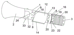
Fig. 1 is a schematic structural diagram of a flashlight with a charger function in embodiment 1;
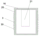
FIG. 2 is a sectional view showing the structure of a desk lamp part in embodiment 1;
fig. 3 is a sectional view showing the internal structure of the handle portion in embodiment 1;
FIG. 4 is a sectional view showing the internal structure of a desk lamp part in embodiment 1;
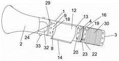
fig. 5 is a schematic structural diagram of a flashlight with a charger function in embodiment 2.
In the figure: a handle portion 1; an illuminating lamp 2; a desk lamp part 3; a first lamp body 4; a battery panel 5; a control panel 6; a solar energy conversion circuit board 7; a first USB interface 8; an illumination lamp control switch 9; a mounting bracket 10; a winding shaft 11; a flexible solar panel 12; a through hole 13; a sleeve 14; a torsion spring 15; a first magnet 16; a first iron piece 17; a first MicroUSB interface 18; a second lamp body 19; an LED lamp bead 20; a rechargeable battery 21; a second USB interface 22; a first switch 23; a second switch 24; a strip mounting groove 25; a support frame 26; a ring magnet 27; an annular iron sheet 28; a night light bar 29; a slip prevention section 30; a rotary positioning groove 31; an extension 32; the positioning shaft 33 is rotated.
Detailed Description
The technical solutions in the embodiments of the present invention will be clearly and completely described below with reference to the drawings in the embodiments of the present invention, and it is obvious that the described embodiments are only a part of the embodiments of the present invention, and not all of the embodiments.
Example 1:
referring to fig. 1-4, the flashlight with a charger function disclosed in this embodiment includes a flashlight body, the flashlight body includes a handle portion 1, an illuminating lamp 2 and a desk lamp portion 3, a rear end of the illuminating lamp 2 is hinged to a front end of the handle portion 1, a rechargeable battery panel 5, a control panel 6 electrically connected to the battery panel 5 and the illuminating lamp 2, and a solar energy conversion circuit board 7 for converting solar energy into electric energy are disposed in the handle portion 1, a first USB interface 8, a first microsub interface 18, an illuminating lamp control switch 9, and more than one circle of first lamp bodies 4 are annularly disposed on an outer wall of the handle portion 1, the solar energy conversion circuit board 7 is electrically connected to the battery panel 5, a mounting bracket 10 is disposed on an inner wall of the handle portion 1, a winding shaft 11 penetrates through the mounting bracket 10, and a flexible solar panel 12 is wound on the winding shaft 11, one end of the flexible solar panel 12 extends out of the through hole 13 on the handle part 1 and then is connected with a sleeve 14, the upper and lower ends of the winding shaft 11 are respectively provided with a torsion spring 15 rotating along with the winding shaft 11, the other end of the torsion spring 15 is connected with the winding shaft 11, the other end of the torsion spring 15 is fixedly connected with the mounting support 10, the flexible solar panel 12 is electrically connected with the solar energy conversion circuit board 7, the upper end of the desk lamp part 3 is connected with a first magnet 16, the lower part of the handle part 1 is connected with a first iron sheet 17 matched with the first magnet 16, the outer wall of the desk lamp part 3 is provided with a second lamp body 19 with more than one circle in an annular distribution manner, the first lamp body 4 and the second lamp body 19 both comprise more than one LED lamp beads 20, a charging battery 21 is arranged in the desk lamp part 3, the desk lamp part 3 is provided with a second USB interface 22 electrically connected with the charging battery 21 and a first switch 23 electrically connected with the control panel 6 and controlling the second lamp body 19, the side of the handle part 1 is also provided with a second switch 24 which is electrically connected with the control panel 6 and controls the first lamp body 4, the bottom of the desk lamp part 3 is provided with three strip-shaped mounting grooves 25 which are distributed in a triangular manner, each strip-shaped mounting groove 25 is rotatably connected with a support frame 26, and the three support frames 26 form a tripod after being opened.
The following technical effects are realized through the structure setting:
1. realize multi-functionally, first kind function: when the desk lamp is used as a temporary small desk lamp, the desk lamp part 3 is detached from the illuminating lamp 2; the second function is as follows: when the flashlight is used as a common flashlight, the lighting lamp control switch 9 is turned on, and the lighting lamp 2 is turned on at the moment and is used as a flashlight; the third function is: when the charger is used as a charger, the first USB interface 8 is used as an input port, an external 5V power supply can be connected into the charger, and then the rechargeable battery panel 5 is charged; the first MicroUSB interface 18 is used as an output port, and products needing 5V charging can be charged at the later stage; the second USB interface 22 is used as an input port, and the temporary small table lamp is connected with the first MicroUSB interface 18 through a data line to charge the internal rechargeable battery 21; fourthly, the three support frames 26 below the desk lamp part 3 are opened to form a tripod, the second lamp body 19 and the first lamp body 4 of the device are all opened to be used as the vehicle emergency warning lamp, and the detachable desk lamp part 3 is used for absorbing the magnet of the first magnet 16 at the bottom of the desk lamp part 3 on the roof of the automobile to be used as the fault warning lamp.
2. At open-air camping in-process, when the flashlight is electroless, can pull out sleeve 14 daytime, peg graft a rod on the sleeve and fix on ground, then pull out flexible solar panel 12 and carry out solar charging to inside panel 5, when the pulling, the torsional spring is pulled up, the completion back of charging, external force disappears the back, utilizes the torsional spring 15 of the upper and lower both sides of coiling axle 11 to reset, does not account for the space, conveniently accomodates flexible solar panel 12.
3. And the rear end of the illuminating lamp 2 is hinged with the front end of the handle part 1, so that the illumination angle is adjustable.
Further, for the convenience of fixing, be provided with annular magnet 27 in each rectangular mounting groove 25, be provided with on each support frame 26 with annular magnet 27 complex annular iron sheet 28, through setting up annular magnet 27 and annular iron sheet 28, when accomodating support frame 26, can play the fixed action to support frame 26, avoid the time spent not, support frame 26 is opened by oneself.
Further, when holding, play the antiskid effect, still be provided with antiskid portion 30 outside desk lamp portion 3, through setting up antiskid portion 30, when holding, play the antiskid effect.
Further, for convenient operation, be provided with rotation positioning groove 31 at the front end of handle portion 1, illumination lamp 2 rear end is provided with the extension 32 that inserts in rotation positioning groove 31, pegs graft on extension 32 and rotation positioning groove 31 and has a rotation positioning axle 33 that runs through handle portion 1, sets up the illumination angle that conveniently adjusts illumination lamp 2 through above-mentioned structure.
Example 2:
referring to fig. 5, the flashlight with a function of a power bank disclosed in this embodiment further facilitates finding the device quickly at night, and more than one night light bar 29 is further disposed outside the handle portion 1.
The above description is only for the preferred embodiment of the present invention, but the scope of the present invention is not limited thereto, and any person skilled in the art should be considered to be within the technical scope of the present invention, and equivalent alternatives or modifications according to the technical solution of the present invention and the inventive concept thereof should be covered by the scope of the present invention.
Claims (5)
1. The utility model provides a flashlight with precious function charges, includes the flashlight body, its characterized in that: the flashlight body comprises a handle part (1), a lighting lamp (2) and a desk lamp part (3), the rear end of the lighting lamp (2) is hinged with the front end of the handle part (1), a rechargeable battery panel (5), a control panel (6) electrically connected with the battery panel (5) and the lighting lamp (2) and a solar energy conversion circuit board (7) for converting solar energy into electric energy are arranged in the handle part (1), a first USB interface (8), a first MicroUSB interface (18), a lighting lamp control switch (9) and more than one circle of first lamp bodies (4) are annularly distributed on the outer wall of the handle part (1), the solar energy conversion circuit board (7) is electrically connected with the battery panel (5), a mounting support (10) is arranged on the inner wall of the handle part (1), a winding shaft (11) penetrates through the mounting support (10), and a flexible solar panel (12) is wound on the winding shaft (11), one end of the flexible solar panel (12) extends out of a through hole (13) in the handle part (1) and then is connected with a sleeve (14), a torsion spring (15) rotating along with the winding shaft (11) is arranged at each of the upper end and the lower end of the winding shaft (11), the other end of the torsion spring (15) is connected with the winding shaft (11), the other end of the torsion spring (15) is fixedly connected with the mounting support (10), the flexible solar panel (12) is electrically connected with the solar energy conversion circuit board (7), the upper end of the desk lamp part (3) is connected with a first magnet (16), a first iron sheet (17) matched with the first magnet (16) is connected below the handle part (1), more than one circle of second lamp bodies (19) are annularly distributed on the outer wall of the desk lamp part (3), and the first lamp bodies (4) and the second lamp bodies (19) both comprise more than one LED lamp bead (20), the novel desk lamp comprises a desk lamp part (3), wherein a rechargeable battery (21) is arranged in the desk lamp part (3), a second USB interface (22) electrically connected with the rechargeable battery (21) and a first switch (23) electrically connected with a control board (6) and controlling a second lamp body (19) are arranged on the desk lamp part (3), a second switch (24) electrically connected with the control board (6) and controlling a first lamp body (4) is further arranged on the side edge of the handle part (1), three strip mounting grooves (25) which are distributed in a triangular shape are formed in the bottom of the desk lamp part (3), a support frame (26) is rotationally connected in each strip mounting groove (25), and a tripod is formed after the three support frames (26) are opened.
2. The flashlight of claim 1, wherein the flashlight further comprises: an annular magnet (27) is arranged in each strip mounting groove (25), and an annular iron sheet (28) matched with the annular magnet (27) is arranged on each support frame (26).
3. A flashlight with a charger function according to claim 1 or 2, wherein: an anti-skid part (30) is arranged outside the desk lamp part (3).
4. A flashlight with a charger function according to claim 1 or 2, wherein: the front end of the handle part (1) is provided with a rotary positioning groove (31), the rear end of the illuminating lamp (2) is provided with an extension part (32) inserted into the rotary positioning groove (31), and a rotary positioning shaft (33) penetrating through the handle part (1) is inserted into the extension part (32) and the rotary positioning groove (31).
5. A flashlight with a charger function according to claim 1 or 2, wherein: more than one luminous bar (29) is arranged outside the handle part (1).
Priority Applications (1)
| Application Number | Priority Date | Filing Date | Title |
|---|---|---|---|
| CN202120619629.XU CN215674843U (en) | 2021-03-26 | 2021-03-26 | Flashlight with precious function charges |
Applications Claiming Priority (1)
| Application Number | Priority Date | Filing Date | Title |
|---|---|---|---|
| CN202120619629.XU CN215674843U (en) | 2021-03-26 | 2021-03-26 | Flashlight with precious function charges |
Publications (1)
| Publication Number | Publication Date |
|---|---|
| CN215674843U true CN215674843U (en) | 2022-01-28 |
Family
ID=79969610
Family Applications (1)
| Application Number | Title | Priority Date | Filing Date |
|---|---|---|---|
| CN202120619629.XU Expired - Fee Related CN215674843U (en) | 2021-03-26 | 2021-03-26 | Flashlight with precious function charges |
Country Status (1)
| Country | Link |
|---|---|
| CN (1) | CN215674843U (en) |
-
2021
- 2021-03-26 CN CN202120619629.XU patent/CN215674843U/en not_active Expired - Fee Related
Similar Documents
| Publication | Publication Date | Title |
|---|---|---|
| CN203762442U (en) | Multifunctional solar outdoor parasol | |
| CN102927518A (en) | Multifunctional solar table lamp | |
| CN215674843U (en) | Flashlight with precious function charges | |
| CN202302777U (en) | Movable multifunctional light-emitting diode (LED) lamp | |
| CN206398619U (en) | Street lamp illuminating device | |
| CN110822310B (en) | Lighting lamp for camping | |
| CN209540737U (en) | A kind of portable dual-purpose solar lamp | |
| CN209196597U (en) | A kind of indoor-outdoor multipurpose way portable type solar energy lamps and lanterns that can be applied in combination | |
| CN205716600U (en) | A kind of new type solar energy lantern | |
| CN215294616U (en) | LED portable working lamp | |
| CN201292969Y (en) | Portable fan | |
| CN205824895U (en) | A kind of student dormitory solar energy desk lamp | |
| CN206522640U (en) | A kind of many charging modes integrated emergency lamps | |
| CN215603630U (en) | Multifunctional umbrella | |
| CN2345033Y (en) | Combined multipurpose umbrella | |
| CN208222338U (en) | A kind of LED worklight | |
| CN214156421U (en) | Universal multifunctional handle | |
| CN208817355U (en) | There are two types of charging modes and the Foldable desk lamps that can power for a kind of tool | |
| CN209960369U (en) | LED lamp sticker | |
| CN211600522U (en) | Practical function lamp pole | |
| CN204005308U (en) | USB solar lamp | |
| CN207815146U (en) | L ED lamp using solar energy as storage battery | |
| CN215580495U (en) | Vehicle-mounted mobile phone base capable of being charged wirelessly | |
| CN221042368U (en) | Portable small-size outdoor energy memory | |
| CN202327958U (en) | Folding table lamp provided with flashlight |
Legal Events
| Date | Code | Title | Description |
|---|---|---|---|
| GR01 | Patent grant | ||
| GR01 | Patent grant | ||
| CF01 | Termination of patent right due to non-payment of annual fee | ||
| CF01 | Termination of patent right due to non-payment of annual fee |
Granted publication date: 20220128 |