CN215618279U - Bread partitioning device for food processing - Google Patents
Bread partitioning device for food processing Download PDFInfo
- Publication number
- CN215618279U CN215618279U CN202121048528.8U CN202121048528U CN215618279U CN 215618279 U CN215618279 U CN 215618279U CN 202121048528 U CN202121048528 U CN 202121048528U CN 215618279 U CN215618279 U CN 215618279U
- Authority
- CN
- China
- Prior art keywords
- support
- bread
- spring
- sliding sleeve
- sliding
- Prior art date
- Legal status (The legal status is an assumption and is not a legal conclusion. Google has not performed a legal analysis and makes no representation as to the accuracy of the status listed.)
- Active
Links
Images


Abstract
The utility model relates to the technical field of bread partitioning equipment, in particular to a bread partitioning device for food processing. The utility model provides a bread partitioning device for food processing, which can greatly improve bread cutting efficiency, save labor, save cost for enterprises and realize full-automatic rapid one-step forming, cutting and trimming. A bread partitioning device for food processing comprises a base, a first bracket, a supporting frame, a sliding plate, a first spring and the like; the middle part both sides all are equipped with first support on the base, all are equipped with the support frame on the first support of both sides, and the slidingtype is equipped with the slide between two support frame lower parts, and equal symmetrical connection has first spring between the left and right sides of slide and the support frame. Through being equipped with and passing the material mechanism, the motor output shaft drives sector gear operation, and sector gear and first straight gear meshing and separation for conveyer belt intermittent type nature operation can reach the effect of intermittent type nature pay-off.
Description
Technical Field
The utility model relates to the technical field of bread partitioning equipment, in particular to a bread partitioning device for food processing.
Background
The bread is a baked food processed by taking wheat as a main material, has the advantages of being fragrant, soft, delicious and the like, and is deeply favored by people; however, in the process of bread making, large bread is usually made and then cut, but nowadays, the bread is usually cut by a cutter by workers, and the bread is trimmed again for the beauty of the bread, so that the cutting and trimming efficiency is slow and has large errors, which causes the quality of finished products to be reduced, affects the selling phase of the bread and is not beneficial to packaging, and simultaneously causes great waste.
Therefore, the bread partitioning device for food processing, which can greatly improve the bread cutting efficiency, save labor, save cost for enterprises and realize full-automatic rapid one-step forming, cutting and trimming, needs to be designed aiming at the problems.
SUMMERY OF THE UTILITY MODEL
In order to overcome the defects that the finished product quality is reduced due to the fact that the cutting and trimming efficiency is slow and large errors are caused when people use a cutter to cut and trim the bread, the technical problem of the utility model is as follows: the bread partitioning device for food processing is capable of greatly improving bread cutting efficiency, saving labor, saving cost for enterprises and achieving full-automatic rapid one-step forming, cutting and trimming.
The technical scheme of the utility model is as follows: the utility model provides a bread piecemeal device for food processing, including base, first support, support frame, slide, first spring, cutter and biography material mechanism, the middle part both sides all are equipped with first support on the base, all are equipped with the support frame on the first support of both sides, and the slidingtype is equipped with the slide between two support frame lower parts, and equal symmetric connection has first spring between the left and right sides of slide and the support frame, and the slide bottom is equipped with the cutter, is equipped with between base and the support frame and passes the material mechanism, passes the material mechanism to be located the cutter below.
Further, pass material mechanism including the second support, including a motor, an end cap, a controller, and a cover plate, the motor, sector gear, the third support, the cylinder, the conveyer belt, first right-hand gear and receipts material frame, base rear portion right side is equipped with the second support, the motor is installed at second support top, motor output shaft rear end is equipped with sector gear, base front and back both sides all are equipped with the third support, interior rotary type is equipped with the cylinder between two third support upper portions of horizontal homonymy, be connected with the conveyer belt between two cylinders, rear side cylinder right-hand member is equipped with first right-hand gear, first right-hand gear and sector gear meshing, the front side is equipped with receipts material frame on the base, it is located conveyer belt front lower place to receive the material frame.
Further, patting mechanism is including the fourth support, the second straight-teeth gear, cam and drive assembly, base rear portion right side is equipped with the fourth support, the fourth support is located second support left front place, the rotary type is equipped with the second straight-teeth gear in fourth support upper portion, second straight-teeth gear and sector gear and meshing, internal rotation formula is equipped with the cam between two support frame upper portions, be connected with drive assembly between cam right-hand member and the second straight-teeth gear middle part, drive assembly comprises two belt pulleys and belt, establish respectively on cam and second straight-teeth gear for two belt pulleys, the belt is around between two belt pulleys.
Further comprises a blanking mechanism, the blanking mechanism comprises a first sliding sleeve, a wedge block, a second spring, a discharging frame, a sliding rod, a second sliding sleeve, a first baffle plate, a second baffle plate and a third spring, the conveyor belt is provided with the first sliding sleeve, the wedge block is arranged in the first sliding sleeve in a sliding way, the second spring is wound on the wedge block, the upper end and the lower end of the second spring are respectively connected with the wedge block and the first sliding sleeve, the right side of the rear part of the base is provided with the discharging frame, the left part of the discharging frame is positioned right above the conveyor belt, the sliding rod is arranged between the front left side and the rear left side of the front part and the rear part of the discharging frame, the lower part of the sliding rod is provided with the second sliding sleeve in a sliding way, the third spring is wound on the sliding rod, the front end and the rear end of the third spring are respectively connected with the sliding rod and the second sliding sleeve, the rear end of the left side of the second sliding sleeve is in contact fit with the wedge block, the right front side of the top of the second sliding sleeve is provided with the first baffle plate, the first baffle plate is in sliding fit with the lower part of the discharging frame, and a second baffle is arranged at the rear end of the bottom of the second sliding sleeve, and the top of the second baffle is in sliding fit with the bottom of the left side of the material placing frame.
Further, still including clamping mechanism, clamping mechanism is including connecting rod, third sliding sleeve, clamp splice and fourth spring, and the anterior left and right sides symmetry of slide is equipped with the connecting rod, and two support frame antetheca downside all are equipped with the third sliding sleeve, and two equal inward sliding formulas of third sliding sleeve are equipped with the clamp splice, and the contact cooperation of lower extreme before clamp splice outer end and the connecting rod has around the fourth spring on the clamp splice, and the fourth spring both ends are connected with third sliding sleeve and clamp splice respectively.
Has the advantages that: 1. the material conveying mechanism is arranged, the motor output shaft drives the sector gear to operate, and the sector gear is meshed with and separated from the first straight gear, so that the conveyor belt operates intermittently, and the effect of intermittent feeding can be achieved.
2. Through being equipped with beater mechanism, cam and slide intermittent type nature contact are patted to make slide and cutter up-and-down reciprocating motion, realize the cutter intermittent type nature and cut the effect of cutting big bread.
3. Through being equipped with unloading mechanism, first baffle and second baffle reciprocating motion and the cooperation of blowing frame reach the purpose of intermittent type nature unloading.
4. Through being equipped with clamping mechanism, two clamp splice relative inward movements reach and press from both sides the bold bread on the firm conveyer belt of clamp, ensure to cooperate the cutter more accurately and cut the purpose of bold bread.
Drawings
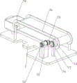
Fig. 1 is a schematic perspective view of the present invention.
Fig. 2 is a schematic perspective view of the material conveying mechanism of the present invention.
Fig. 3 is a schematic perspective view of a flapping mechanism of the present invention.
Fig. 4 is a schematic perspective view of the blanking mechanism of the present invention.
Fig. 5 is a schematic perspective view of the clamping mechanism of the present invention.
The parts are labeled as follows: 1. the automatic feeding device comprises a base, 2, a first support, 3, a support frame, 4, a sliding plate, 5, a first spring, 6, a cutter, 7, a material conveying mechanism, 71, a second support, 72, a motor, 73, a sector gear, 74, a third support, 75, a roller, 76, a conveyor belt, 77, a first straight gear, 78, a material collecting frame, 8, a beating mechanism, 81, a fourth support, 82, a second straight gear, 83, a cam, 84, a transmission assembly, 9, a discharging mechanism, 91, a first sliding sleeve, 92, a wedge block, 93, a second spring, 94, a material discharging frame, 95, a sliding rod, 96, a second sliding sleeve, 97, a first baffle, 98, a second baffle, 99, a third spring, 10, a clamping mechanism, 101, a connecting rod, 102, a third sliding sleeve, 103, a clamping block, 104 and a fourth spring.
Detailed Description
Although the present invention may be described with respect to particular applications or industries, those skilled in the art will recognize the broader applicability of the utility model. Those of ordinary skill in the art will recognize other factors such as: terms such as above, below, upward, downward, and the like are used to describe the accompanying drawings and are not meant to limit the scope of the utility model, which is defined by the appended claims. Such as: any numerical designation of first or second, and the like, is merely exemplary and is not intended to limit the scope of the utility model in any way.
Example 1
The utility model provides a bread piecemeal device for food processing, as shown in figure 1 and figure 2, including base 1, first support 2, support frame 3, slide 4, first spring 5, cutter 6 and biography material mechanism 7, the middle part both sides all are equipped with first support 2 on the base 1, all be equipped with support frame 3 on the first support 2 of both sides, the internal sliding formula is equipped with slide 4 between two support frame 3 lower parts, equal symmetrical connection has first spring 5 between the left and right sides of slide 4 and the support frame 3, slide 4 bottom is equipped with cutter 6, be equipped with between base 1 and the support frame 3 and pass material mechanism 7, it is located cutter 6 below to pass material mechanism 7.
When people need to cut and trim the big bread, the bread partitioning device for food processing can be used, firstly, the big bread is placed at the rear part of the material conveying mechanism 7, then the material conveying mechanism 7 is started, the material conveying mechanism 7 operates to drive the big bread to move forwards, when the bread is conveyed below the cutter 6, people press the sliding plate 4 downwards, the first spring 5 is stretched to drive the cutter 6 to move downwards, the cutter 6 cuts and trims the conveyed bread, the purpose of cutting a plurality of small bread at one time is achieved, after cutting and trimming, the sliding plate 4 is loosened, the first spring 5 resets, the cutter 6 and the sliding plate 4 both move upwards, and therefore, the next big bread can be cut and molded quickly in a reciprocating mode, and when the big bread does not need to be cut and trimmed, the material conveying mechanism 7 is closed.
The material conveying mechanism 7 comprises a second support 71, a motor 72, a sector gear 73, a third support 74, a roller 75, a conveyor belt 76, a first straight gear 77 and a material receiving frame 78, the second support 71 is arranged on the right side of the rear portion of the base 1, the motor 72 is installed at the top of the second support 71, the sector gear 73 is arranged at the rear end of an output shaft of the motor 72, the third support 74 is arranged on the front side and the rear side of the base 1, the roller 75 is arranged on the upper portion of the two third supports 74 on the same transverse side in a rotating mode, the conveyor belt 76 is connected between the two rollers 75, the first straight gear 77 is arranged at the right end of the roller 75 on the rear side, the first straight gear 77 is meshed with the sector gear 73, the material receiving frame 78 is arranged on the front side of the base 1, and the material receiving frame 78 is located below the front of the conveyor belt 76.
When people need to cut and trim the large bread, the large bread is firstly placed on the conveyor belt 76, then the motor 72 is started, the output shaft of the motor 72 drives the sector gear 73 to operate, when the sector gear 73 is meshed with the first straight gear 77, the first straight gear 77 is driven to operate, the conveyor belt 76 is driven to operate, and then the large bread is driven to move forward, when the sector gear 73 is not meshed with the first straight gear 77, the first straight gear 77 and the conveyor belt 76 stop operating, and the large bread stops moving forward.
Example 2
Based on embodiment 1, as shown in fig. 3-5, the patting mechanism 8 includes a fourth bracket 81, a second spur gear 82, a cam 83 and a transmission assembly 84, the fourth bracket 81 is disposed on the right side of the rear portion of the base 1, the fourth bracket 81 is disposed in front of the second bracket 71, the second spur gear 82 is rotatably disposed in the upper portion of the fourth bracket 81, the second spur gear 82 is engaged with the sector gear 73, the cam 83 is rotatably disposed between the upper portions of the two support frames 3, the transmission assembly 84 is connected between the right end of the cam 83 and the middle portion of the second spur gear 82, the transmission assembly 84 is composed of two pulleys and a belt, the two pulleys are disposed on the cam 83 and the second spur gear 82 respectively, and the belt is wound between the two pulleys.
After the motor 72 is started, the sector gear 73 drives the second straight gear 82 to operate, the cam 83 is driven to operate through the transmission assembly 84, the cam 83 intermittently contacts and beats with the sliding plate 4, so that the sliding plate 4 and the cutter 6 can do up-and-down reciprocating motion, and the effect that the cutter 6 intermittently cuts the bread can be realized.
The blanking mechanism 9 comprises a first sliding sleeve 91, a wedge-shaped block 92, a second spring 93, a material placing frame 94, a sliding rod 95, a second sliding sleeve 96, a first baffle 97, a second baffle 98 and a third spring 99, wherein the conveyor belt 76 is provided with the first sliding sleeve 91, the first sliding sleeve 91 is internally provided with the wedge-shaped block 92 in a sliding manner, the second spring 93 is wound on the wedge-shaped block 92, the upper end and the lower end of the second spring 93 are respectively connected with the wedge-shaped block 92 and the first sliding sleeve 91, the right side of the rear part of the base 1 is provided with the material placing frame 94, the left part of the material placing frame 94 is positioned right above the conveyor belt 76, the sliding rod 95 is arranged between the left side of the front part and the rear part of the material placing frame 94, the lower part of the sliding rod 95 is provided with the second sliding sleeve 96 in a sliding manner, the third spring 99 is wound on the sliding rod 95, the front end and the rear end of the third spring 99 are respectively connected with the sliding rod 95 and the second sliding sleeve 96, the rear end of the left side of the second sliding sleeve 96 is in contact fit with the wedge-shaped block 92, the right side of the top of the second sliding sleeve 96 is provided with the first baffle 97, the first baffle 97 is slidably engaged with the lower portion of the material placing frame 94, the second baffle 98 is disposed at the rear end of the bottom of the second sliding sleeve 96, and the top of the first baffle 98 is slidably engaged with the bottom of the left side of the material placing frame 94.
When people need to cut and trim the big bread, the big bread is firstly sequentially stacked and placed in the material placing frame 94, after the motor 72 is started, the conveyor belt 76 operates to drive the wedge-shaped block 92 to move forwards, when the wedge-shaped block 92 contacts the left end of the second sliding sleeve 96, the wedge-shaped block 92 is pressed to move downwards, the second spring 93 is compressed, the second sliding sleeve 96 is driven to move forwards, the first baffle 97 and the second baffle 98 are driven to move forwards, when the first baffle 97 moves forwards and leaves the material placing frame 94, the big bread falls onto the second baffle 98, the third spring 99 is compressed, when the wedge-shaped block 92 moves forwards and leaves the left end of the first sliding sleeve 91, the third spring 99 resets, the first baffle 97 and the second baffle 98 move backwards, the first baffle 97 clamps the lower part of the material placing frame 94, the big bread cannot fall, and the big bread on the second baffle 98 falls onto the conveyor belt 76, meanwhile, the second spring 93 is reset, the wedge-shaped block 92 moves upwards and rotates once along with the conveyor belt 76 until the wedge-shaped block is reset, and the intermittent blanking is achieved in a reciprocating mode.
Still including clamping mechanism 10, clamping mechanism 10 is including connecting rod 101, third sliding sleeve 102, clamp splice 103 and fourth spring 104, the anterior left and right sides symmetry of slide 4 is equipped with connecting rod 101, 3 antetheca downside of two support frames all is equipped with third sliding sleeve 102, two equal inward sliding type of third sliding sleeve 102 are equipped with clamp splice 103, the contact cooperation of lower extreme before clamp splice 103 outer end and connecting rod 101, around having fourth spring 104 on the clamp splice 103, fourth spring 104 both ends are connected with third sliding sleeve 102 and clamp splice 103 respectively.
After motor 72 starts, slide 4 drives connecting rod 101 downstream to drive clamp splice 103 inward movement, fourth spring 104 is stretched, thereby reaches the block bread that presss from both sides on the tight conveyer belt 76 of clamp, ensures to cooperate more accurate cutter 6 to cut the purpose of block bread, and when slide 4 drives connecting rod 101 upward movement, cut the bread after, fourth spring 104 resets, makes clamp splice 103 outward movement.
While the present invention has been described with reference to exemplary embodiments, it is to be understood that the utility model is not limited to the disclosed exemplary embodiments. The scope of the following claims is to be accorded the broadest interpretation so as to encompass all such modifications and equivalent structures and functions.
Claims (6)
1. The utility model provides a bread piecemeal device for food processing, including base (1), first support (2), support frame (3), slide (4), first spring (5) and cutter (6), base (1) is gone up the middle part both sides and all is equipped with first support (2), all be equipped with support frame (3) on first support (2) of both sides, the sliding type is equipped with slide (4) between two support frame (3) lower parts, equal symmetric connection has first spring (5) between the left and right sides of slide (4) and support frame (3), slide (4) bottom is equipped with cutter (6), its characterized in that: the automatic feeding device is characterized by further comprising a material conveying mechanism (7), wherein the material conveying mechanism (7) is arranged between the base (1) and the supporting frame (3), and the material conveying mechanism (7) is located below the cutter (6).
2. The bread partitioning apparatus for food processing as set forth in claim 1, wherein: the material conveying mechanism (7) comprises a second bracket (71), a motor (72), a sector gear (73), a third bracket (74), a roller (75), a conveyor belt (76), a first straight gear (77) and a material receiving frame (78), base (1) rear portion right side is equipped with second support (71), motor (72) are installed at second support (71) top, motor (72) output shaft rear end is equipped with sector gear (73), base (1) front and back both sides all are equipped with third support (74), interior rotary type is equipped with cylinder (75) between two third support (74) upper portions of horizontal homonymy, be connected with conveyer belt (76) between two cylinder (75), rear side cylinder (75) right-hand member is equipped with first spur gear (77), first spur gear (77) and sector gear (73) meshing, the front side is equipped with receipts material frame (78) on base (1), it is located conveyer belt (76) front lower place to receive material frame (78).
3. The bread partitioning apparatus for food processing as set forth in claim 2, wherein: patting mechanism (8) is including fourth support (81), second spur gear (82), cam (83) and drive assembly (84), base (1) rear portion right side is equipped with fourth support (81), fourth support (81) are located second support (71) left front place, fourth support (81) upper portion internal rotation formula is equipped with second spur gear (82), second spur gear (82) and sector gear (73) and meshing, internal rotation formula is equipped with cam (83) between two support frame (3) upper portions, be connected with drive assembly (84) between cam (83) right-hand member and second spur gear (82) middle part, drive assembly (84) comprise two belt pulleys and belt, two belt pulleys are established respectively on cam (83) and second spur gear (82), the belt is around between two belt pulleys.
4. The bread partitioning apparatus for food processing as set forth in claim 3, wherein: the blanking mechanism (9) comprises a first sliding sleeve (91), a wedge-shaped block (92), a second spring (93), a material placing frame (94), a sliding rod (95), a second sliding sleeve (96), a first baffle (97), a second baffle (98) and a third spring (99), the conveyor belt (76) is provided with the first sliding sleeve (91), the first sliding sleeve (91) is internally provided with the wedge-shaped block (92) in a sliding manner, the wedge-shaped block (92) is wound with the second spring (93), the upper end and the lower end of the second spring (93) are respectively connected with the wedge-shaped block (92) and the first sliding sleeve (91), the right side of the rear part of the base (1) is provided with the material placing frame (94), the left part of the material placing frame (94) is positioned right above the conveyor belt (76), the sliding rod (95) is arranged between the left sides of the front part and the rear part of the material placing frame (94), the lower part of the sliding rod (95) is provided with the second sliding sleeve (96) in a sliding manner, the sliding rod (95) is wound with a third spring (99), the front end and the rear end of the third spring (99) are respectively connected with the sliding rod (95) and the second sliding sleeve (96), the rear end of the left side of the second sliding sleeve (96) is in contact fit with the wedge block (92), the right front side of the top of the second sliding sleeve (96) is provided with a first baffle (97), the first baffle (97) is in sliding fit with the lower part of the discharging frame (94), the rear end of the bottom of the second sliding sleeve (96) is provided with a second baffle (98), and the top of the second baffle (98) is in sliding fit with the bottom of the left side of the discharging frame (94).
5. The bread partitioning apparatus for food processing as set forth in claim 4, wherein: still including clamping mechanism (10), clamping mechanism (10) are including connecting rod (101), third sliding sleeve (102), clamp splice (103) and fourth spring (104), slide (4) anterior left and right sides symmetry is equipped with connecting rod (101), two support frame (3) antetheca downside all is equipped with third sliding sleeve (102), two equal inward sliding type of third sliding sleeve (102) are equipped with clamp splice (103), the contact cooperation of lower extreme before clamp splice (103) outer end and connecting rod (101), around having fourth spring (104) on clamp splice (103), fourth spring (104) both ends are connected with third sliding sleeve (102) and clamp splice (103) respectively.
6. The bread partitioning apparatus for food processing as set forth in claim 5, wherein: the rear part of the clamping block (103) is made of edible silica gel.
Priority Applications (1)
| Application Number | Priority Date | Filing Date | Title |
|---|---|---|---|
| CN202121048528.8U CN215618279U (en) | 2021-05-17 | 2021-05-17 | Bread partitioning device for food processing |
Applications Claiming Priority (1)
| Application Number | Priority Date | Filing Date | Title |
|---|---|---|---|
| CN202121048528.8U CN215618279U (en) | 2021-05-17 | 2021-05-17 | Bread partitioning device for food processing |
Publications (1)
| Publication Number | Publication Date |
|---|---|
| CN215618279U true CN215618279U (en) | 2022-01-25 |
Family
ID=79938919
Family Applications (1)
| Application Number | Title | Priority Date | Filing Date |
|---|---|---|---|
| CN202121048528.8U Active CN215618279U (en) | 2021-05-17 | 2021-05-17 | Bread partitioning device for food processing |
Country Status (1)
| Country | Link |
|---|---|
| CN (1) | CN215618279U (en) |
Cited By (2)
| Publication number | Priority date | Publication date | Assignee | Title |
|---|---|---|---|---|
| CN114950949A (en) * | 2022-06-16 | 2022-08-30 | 高安市盛发粮油有限公司 | Foreign matter divides sieve device for corn processing |
| CN115091521A (en) * | 2022-06-22 | 2022-09-23 | 刘翠琼 | Automatic cutting system for processing traditional Chinese medicine decoction pieces |
-
2021
- 2021-05-17 CN CN202121048528.8U patent/CN215618279U/en active Active
Cited By (2)
| Publication number | Priority date | Publication date | Assignee | Title |
|---|---|---|---|---|
| CN114950949A (en) * | 2022-06-16 | 2022-08-30 | 高安市盛发粮油有限公司 | Foreign matter divides sieve device for corn processing |
| CN115091521A (en) * | 2022-06-22 | 2022-09-23 | 刘翠琼 | Automatic cutting system for processing traditional Chinese medicine decoction pieces |
Similar Documents
| Publication | Publication Date | Title |
|---|---|---|
| CN215618279U (en) | Bread partitioning device for food processing | |
| EP3616521B1 (en) | Stuffed food forming method | |
| CN112476508B (en) | Rice cake slicing and forming equipment for food processing | |
| EP3616522B1 (en) | Stuffed food forming machine | |
| CN109964970B (en) | Automatic forming equipment of jujube cake | |
| US4014254A (en) | Device for wrapping sheets around food in rolled form and other food processing devices | |
| JP2017521098A (en) | Method and apparatus for producing long food | |
| JP3331303B2 (en) | Noodle peeling device | |
| JPS6331352B2 (en) | ||
| CN107960444B (en) | Shrimp line removing device | |
| CN113772148A (en) | Multi-station laminating machine and battery case laminating operation method based on laminating machine | |
| EP3097784B1 (en) | Apparatus for making al plin ravioli | |
| CN216567950U (en) | Full-automatic stewed noodle production equipment | |
| JP2003333979A (en) | Method for forming food and stamping apparatus used for the same | |
| CN114714107A (en) | Corrugated sandwich frame plate production and processing device | |
| CN112960222B (en) | Slitting and taking equipment and meal making device | |
| CN210445476U (en) | Cake blank making device | |
| CN209732433U (en) | multi-dimensional full-automatic wheaten food machine | |
| CN218184964U (en) | Wonton forming mechanism | |
| CN220717656U (en) | Filter screen cutting and bending device | |
| CN218489232U (en) | Reciprocating bag cutting device of paper-plastic bag making machine set | |
| CN220422939U (en) | Dough cutting machine for processing of flower pastries | |
| CN212763616U (en) | Puff skin slicing equipment | |
| CN220196143U (en) | Double-material-belt forming stamping die | |
| CN219565639U (en) | Conveying equipment for cheese roll production |
Legal Events
| Date | Code | Title | Description |
|---|---|---|---|
| GR01 | Patent grant | ||
| GR01 | Patent grant |