CN215617428U - Accurate numerically control grinder piece collection device - Google Patents
Accurate numerically control grinder piece collection device Download PDFInfo
- Publication number
- CN215617428U CN215617428U CN202122161202.2U CN202122161202U CN215617428U CN 215617428 U CN215617428 U CN 215617428U CN 202122161202 U CN202122161202 U CN 202122161202U CN 215617428 U CN215617428 U CN 215617428U
- Authority
- CN
- China
- Prior art keywords
- frame
- piece
- collecting
- numerically controlled
- gear
- Prior art date
- Legal status (The legal status is an assumption and is not a legal conclusion. Google has not performed a legal analysis and makes no representation as to the accuracy of the status listed.)
- Active
Links
Images


Abstract
The utility model belongs to the technical field of precise numerically controlled grinders, and particularly relates to a scrap collecting device of a precise numerically controlled grinder. This accurate numerically control grinder piece collection device, it is rotatory with even axle to have reached to drive the gear through small-size buncher, it is rotatory to drive the brush ring of connecting roller and connecting roller surface simultaneously, gear and rack toothing drive the installing frame and remove to the direction of collecting the frame, the rotation of brush ring cleans the piece on the platform of numerically control grinder body emery wheel below to the direction of collecting the frame, the groove of striking off on the cowl gets rid of adnexed piece on to the brush ring, make the piece that the numerically control grinder body polished the production to the work piece obtain timely quick clearance, reduce the influence of piece to work piece precision of polishing.
Description
Technical Field
The utility model relates to the technical field of precision numerically controlled grinders, in particular to a chip collecting device of a precision numerically controlled grinder.
Background
A numerically controlled grinder is a machine tool that grinds the surface of a workpiece using a grinding tool. Most grinding machines perform grinding using a grinding wheel rotating at a high speed, and a few grinding machines perform grinding using oilstones, sanding belts and other grinders and free abrasives, such as honing machines, superfinishing machines, sanding belt grinders, grinding machines, polishing machines, and the like. The numerical control grinding machine comprises a numerical control surface grinding machine, a numerical control centerless grinding machine, a numerical control internal and external grinding machine, a numerical control vertical universal grinding machine, a numerical control coordinate grinding machine and a numerical control forming grinding machine;
when the workpiece is ground by the numerical control grinding machine, the workpiece surface is chipped by grinding the workpiece, the chippings fall on a platform on one side of the grinding wheel along with the centrifugal force of the rotation direction of the grinding wheel, a large amount of chippings are accumulated, the grinding precision of the workpiece is influenced, and the workpiece is not convenient to clean.
SUMMERY OF THE UTILITY MODEL
The utility model provides a chip collecting device of a precision numerically controlled grinding machine based on the technical problems that a large amount of chips are accumulated when the existing numerically controlled grinding machine grinds a workpiece, the grinding precision of the workpiece is influenced, and the workpiece is inconvenient to clean.
The utility model provides a scrap collecting device of a precision numerically-controlled grinding machine, which comprises a numerically-controlled grinding machine body, wherein a collecting part and a cleaning part are arranged on the upper surface of the numerically-controlled grinding machine body, the collecting part comprises a slide way and a collecting frame, the slide way is arranged on the upper surface of the middle part of the numerically-controlled grinding machine body, and the inner walls of two sides of the slide way are provided with first guide grooves;
cleaning the part and including the installing frame, the connector has all been seted up to the both sides internal surface of installing frame, the inner wall of connector passes through bearing fixedly connected with even axle, the both ends of even axle extend to the both ends surface of installing frame respectively, the one end surface fixed cover of even axle has connect the gear, the one end fixed surface of installing frame is connected with L shape installation piece, the installing port has been seted up to one side surface of L shape installation piece, the inner wall fixed mounting of installing port has small-size buncher, small-size buncher's main shaft with the one end fixed surface of gear is connected.
Preferably, the inner walls of the two first guide grooves are inserted with guide blocks in a sliding manner, and the surface of one end of each guide block is of a T-shaped structure;
through above-mentioned technical scheme, reached and cooperated between guide block and the first guide way, led to collecting the frame.
Preferably, one side surface of one of the guide blocks is fixedly connected with one side surface of the collecting frame, and a material guide block is fixedly connected with an inner bottom wall at an opening of the collecting frame;
through the technical scheme, the scrap is collected through the collection frame.
Preferably, the upper end of the material guide block facing the inner wall of the collecting frame is in an inclined shape, and one side surface of the other guide block is fixedly connected with one side surface of the material guide block;
through above-mentioned technical scheme, reached through the inside guide piece that sets up of collecting the frame and make the piece when the opening part of gathering the frame, make the piece slide in the collection frame through self gravity through the guide piece.
Preferably, a second guide groove is formed in the surface of one side of the middle of the numerically-controlled grinder body, a roller is fixedly sleeved on the outer surface of the other end of the connecting shaft, and the outer surface of the roller is movably inserted into the inner wall of the second guide groove;
through above-mentioned technical scheme, reached and driven the gyro wheel at second guide way internal rotation when the connecting axle is rotatory, led one side of installing frame.
Preferably, a rack is fixedly connected to the upper surface of the middle part of the numerically controlled grinder body, and the rack is in meshing transmission with the gear;
through above-mentioned technical scheme, it is rotatory to have reached to drive the gear through small-size adjustable speed motor for gear and rack toothing, and then drive the installing frame and remove.
Preferably, the outer surface of the connecting shaft positioned in the mounting frame is fixedly connected with a connecting roller, the outer surface of the connecting roller is fixedly sleeved with a brush ring, the inner surface of the upper end of the mounting frame is fixedly connected with an arc-shaped baffle, and one side of the arc-shaped baffle is provided with a scraping groove;
through above-mentioned technical scheme, reached and got rid of adnexed piece on the brush ring through scraping off the groove on the cowl.
The beneficial effects of the utility model are as follows:
the outer surface of the connecting shaft positioned in the mounting frame is fixedly connected with a connecting roller, the outer surface of the connecting roller is fixedly sleeved with a brush ring, the inner surface of the upper end of the mounting frame is fixedly connected with an arc-shaped baffle, one side of the arc-shaped baffle is provided with a scraping groove, so that the purpose that a small speed regulating motor drives a gear and a connecting shaft to rotate is achieved, simultaneously drives the connecting roller and the brush ring on the outer surface of the connecting roller to rotate, the gear and the rack are meshed to drive the mounting frame to move towards the direction of the collecting frame, the rotation of the brush ring cleans the scraps on the platform below the grinding wheel of the numerical control grinding machine body towards the direction of the collecting frame, the scraping groove on the arc-shaped baffle plate removes the scraps attached on the brush ring, the numerical control grinding machine body can timely and quickly clean the fragments generated by grinding the workpiece, and the influence of the fragments on the grinding precision of the workpiece is reduced.
Drawings
FIG. 1 is a schematic diagram of a precise numerically controlled grinder chip collecting device according to the present invention;
FIG. 2 is a perspective view of a collection frame structure of the collection device for chips of a precision numerically controlled grinder according to the present invention;
FIG. 3 is an exploded view of a cleaning component of the precise numerically controlled grinder debris collection device according to the present invention;
FIG. 4 is a structural sectional view of a collecting frame of the precise numerically controlled grinder chip collecting device according to the present invention;
FIG. 5 is a sectional view of the L-shaped mounting block of the precise numerically controlled grinder chip collecting device according to the present invention;
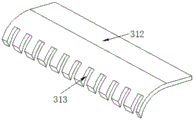
fig. 6 is a perspective view of an arc baffle structure of the precise numerically controlled grinder debris collecting device according to the present invention.
In the figure: 1. a numerically controlled grinder body; 2. a slideway; 21. a first guide groove; 22. a guide block; 23. a collection frame; 24. a material guide block; 3. installing a frame; 31. a connecting port; 32. a connecting shaft; 33. a gear; 34. an L-shaped mounting block; 35. an installation port; 36. a small speed regulating motor; 37. a second guide groove; 38. a roller; 39. a rack; 310. a connecting roller; 311. a brush ring; 312. an arc-shaped baffle plate; 313. scraping the groove.
Detailed Description
The technical solutions in the embodiments of the present invention will be clearly and completely described below with reference to the drawings in the embodiments of the present invention, and it is obvious that the described embodiments are only a part of the embodiments of the present invention, and not all of the embodiments.
Referring to fig. 1-6, a precise numerically controlled grinder debris collecting device comprises a numerically controlled grinder body 1, wherein a collecting part and a cleaning part are arranged on the upper surface of the numerically controlled grinder body 1, the collecting part comprises a slide way 2 and a collecting frame 23, the slide way 2 is arranged on the upper surface of the middle part of the numerically controlled grinder body 1, and first guide grooves 21 are formed in the inner walls of the two sides of the slide way 2;
further, the inner walls of the two first guide grooves 21 are all slidably inserted with guide blocks 22, one end surfaces of the guide blocks 22 are of T-shaped structures, and the purpose that the collection frame 23 is guided by matching the guide blocks 22 with the first guide grooves 21 is achieved.
Furthermore, one side surface of one of the guide blocks 22 is fixedly connected with one side surface of the collecting frame 23, and the inner bottom wall of the opening of the collecting frame 23 is fixedly connected with the material guide block 24, so that the debris is collected together through the collecting frame 23.
Furthermore, the upper end of the material guiding block 24 facing the inner wall of the collecting frame 23 is in an inclined shape, and one side surface of the other guiding block 22 is fixedly connected with one side surface of the material guiding block 24, so that when the debris reaches the opening of the collecting frame 23 by arranging the material guiding block 24 in the collecting frame 23, the debris slides into the collecting frame 23 through the material guiding block 24 by self gravity;
the cleaning component comprises a mounting frame 3, the inner surfaces of two sides of the mounting frame 3 are respectively provided with a connecting port 31, the inner wall of each connecting port 31 is fixedly connected with a connecting shaft 32 through a bearing, two ends of each connecting shaft 32 respectively extend to the outer surfaces of two ends of the mounting frame 3, and the outer surface of one end of each connecting shaft 32 is fixedly sleeved with a gear 33;
furthermore, a second guide groove 37 is formed in the surface of one side of the middle of the numerically controlled grinder body 1, a roller 38 is fixedly sleeved on the outer surface of the other end of the connecting shaft 32, and the outer surface of the roller 38 is movably inserted into the inner wall of the second guide groove 37, so that the connecting shaft 32 is rotated while the roller 38 is driven to rotate in the second guide groove 37, and one side of the mounting frame 3 is guided;
an L-shaped mounting block 34 is fixedly connected to the surface of one end of the mounting frame 3, a mounting opening 35 is formed in the surface of one side of the L-shaped mounting block 34, a small speed regulating motor 36 is fixedly mounted on the inner wall of the mounting opening 35, and a main shaft of the small speed regulating motor 36 is fixedly connected with the surface of one end of the gear 33;
further, the rack 39 is fixedly connected to the upper surface of the middle portion of the numerically controlled grinder body 1, the rack 39 is in meshing transmission with the gear 33, and the purpose that the gear 33 is driven to rotate through the small speed regulating motor 36 is achieved, so that the gear 33 is meshed with the rack 39, and the mounting frame 3 is driven to move.
Further, even axle 32 is located the inside outer fixed surface of installing frame 3 and is connected roller 310, and the outer fixed surface that connects roller 310 cup joints brush ring 311, and the upper end internal surface fixed connection of installing frame 3 has cowl 312, and one side of cowl 312 has been seted up and has been scraped groove 313, has reached and has been got rid of adnexed piece on brush ring 311 through scraping groove 313 on cowl 312.
It is rotatory with even axle 32 to have reached to drive gear 33 through small-size buncher 36, it is rotatory to drive brush ring 311 who connects roller 310 and connect roller 310 surface simultaneously, gear 33 and rack 39 meshing drive installing frame 3 and remove to the direction of collecting frame 23, the rotation of brush ring 311 cleans the piece on the platform of numerically control grinder body 1 emery wheel below to the direction of collecting frame 23, strike off groove 313 on the cowl 312 and get rid of adnexed piece on brush ring 311, make the piece that the numerically control grinder body 1 produced to the work piece is polished and is obtained timely quick clearance, reduce the influence of piece to the precision of polishing of work piece.
The working principle is as follows: during the use, start small-size buncher 36, small-size buncher 36 drives gear 33 rotatory, and then it is rotatory to drive connecting shaft 32, it is rotatory to drive brush ring 311 who connects roller 310 and connect roller 310 surface simultaneously, gear 33 and rack 39 meshing drive installing frame 3 and remove to the direction of collecting frame 23, the rotation of brush ring 311 cleans the piece on the platform of numerically controlled grinder body 1 emery wheel below to the direction of collecting frame 23, when having attached to the piece on brush ring 311, when brush ring 311 and cowl 312 contact, curette ring 313 on cowl 312 gets rid of adnexed piece on brush ring 311, until brush ring 311 sweeps the piece to collecting frame 23 in, the staff can take out collecting frame 23 from slide 2, clear away the piece.
The above description is only for the preferred embodiment of the present invention, but the scope of the present invention is not limited thereto, and any person skilled in the art should be considered to be within the technical scope of the present invention, and equivalent alternatives or modifications according to the technical solution of the present invention and the inventive concept thereof should be covered by the scope of the present invention.
Claims (7)
1. The utility model provides a precision numerically control grinder piece collection device, includes numerically control grinder body (1), its characterized in that: the collecting part and the cleaning part are arranged on the upper surface of the numerical control grinding machine body (1), the collecting part comprises a slide way (2) and a collecting frame (23), the slide way (2) is arranged on the upper surface of the middle part of the numerical control grinding machine body (1), and first guide grooves (21) are formed in the inner walls of the two sides of the slide way (2);
cleaning the part and including installing frame (3), connector (31) have all been seted up to the both sides internal surface of installing frame (3), the inner wall of connector (31) passes through bearing fixedly connected with even axle (32), the both ends of even axle (32) extend to the both ends surface of installing frame (3) respectively, the fixed cover of one end surface of even axle (32) has connect gear (33), the one end fixed surface of installing frame (3) is connected with L shape installation piece (34), installing port (35) have been seted up to one side surface of L shape installation piece (34), the inner wall fixed mounting of installing port (35) has small-size buncher (36), the main shaft of small-size buncher (36) with the one end fixed surface of gear (33) is connected.
2. The precise numerically controlled grinder chip collecting device according to claim 1, wherein: the inner walls of the two first guide grooves (21) are inserted with guide blocks (22) in a sliding mode, and the surface of one end of each guide block (22) is of a T-shaped structure.
3. The precise numerically controlled grinder chip collecting device according to claim 2, wherein: one side surface of one of the guide blocks (22) is fixedly connected with one side surface of the collecting frame (23), and a material guide block (24) is fixedly connected to the inner bottom wall of the opening of the collecting frame (23).
4. The precise numerically controlled grinder chip collection device according to claim 3, wherein: the upper end of the material guide block (24) facing the inner wall of the collecting frame (23) is in an inclined shape, and one side surface of the other guide block (22) is fixedly connected with one side surface of the material guide block (24).
5. The precise numerically controlled grinder chip collecting device according to claim 1, wherein: a second guide groove (37) is formed in the surface of one side of the middle of the numerical control grinding machine body (1), a roller (38) is fixedly sleeved on the outer surface of the other end of the connecting shaft (32), and the outer surface of the roller (38) is movably connected with the inner wall of the second guide groove (37) in an inserting mode.
6. The precise numerically controlled grinder chip collecting device according to claim 1, wherein: the upper surface of the middle part of the numerical control grinding machine body (1) is fixedly connected with a rack (39), and the rack (39) is in meshing transmission with the gear (33).
7. The precise numerically controlled grinder chip collecting device according to claim 1, wherein: even axle (32) are located the inside fixed surface of installing frame (3) is connected with connecting roller (310), the fixed surface of connecting roller (310) is cup jointed brush ring (311), the upper end internal surface fixed connection of installing frame (3) has cowl (312), one side of cowl (312) has been seted up and has been scraped groove (313).
Priority Applications (1)
| Application Number | Priority Date | Filing Date | Title |
|---|---|---|---|
| CN202122161202.2U CN215617428U (en) | 2021-09-08 | 2021-09-08 | Accurate numerically control grinder piece collection device |
Applications Claiming Priority (1)
| Application Number | Priority Date | Filing Date | Title |
|---|---|---|---|
| CN202122161202.2U CN215617428U (en) | 2021-09-08 | 2021-09-08 | Accurate numerically control grinder piece collection device |
Publications (1)
| Publication Number | Publication Date |
|---|---|
| CN215617428U true CN215617428U (en) | 2022-01-25 |
Family
ID=79911520
Family Applications (1)
| Application Number | Title | Priority Date | Filing Date |
|---|---|---|---|
| CN202122161202.2U Active CN215617428U (en) | 2021-09-08 | 2021-09-08 | Accurate numerically control grinder piece collection device |
Country Status (1)
| Country | Link |
|---|---|
| CN (1) | CN215617428U (en) |
Cited By (2)
| Publication number | Priority date | Publication date | Assignee | Title |
|---|---|---|---|---|
| CN114714205A (en) * | 2022-03-23 | 2022-07-08 | 安徽信息工程学院 | Steel billet surface mirror finishing device |
| CN115070574A (en) * | 2022-06-30 | 2022-09-20 | 滁州市盛捷新材料有限公司 | Ice making groove surface machining device |
-
2021
- 2021-09-08 CN CN202122161202.2U patent/CN215617428U/en active Active
Cited By (3)
| Publication number | Priority date | Publication date | Assignee | Title |
|---|---|---|---|---|
| CN114714205A (en) * | 2022-03-23 | 2022-07-08 | 安徽信息工程学院 | Steel billet surface mirror finishing device |
| CN115070574A (en) * | 2022-06-30 | 2022-09-20 | 滁州市盛捷新材料有限公司 | Ice making groove surface machining device |
| CN115070574B (en) * | 2022-06-30 | 2023-10-20 | 滁州市盛捷新材料有限公司 | Ice making groove surface machining device |
Similar Documents
| Publication | Publication Date | Title |
|---|---|---|
| CN215617428U (en) | Accurate numerically control grinder piece collection device | |
| CN209902943U (en) | Anti-rotation angular deformation roller contact type polishing machine for edge polishing of ceramic sheets | |
| CN213532073U (en) | Burnishing device with adjustable metalworking is used | |
| CN215616930U (en) | Blank grinding device is used in production of wear-resisting carborundum axle sleeve | |
| CN220094263U (en) | Grinding machine convenient to clearance is collected sweeps | |
| CN216608291U (en) | Grinding wheel assembling structure of cylindrical grinding machine | |
| CN219853647U (en) | Burr removing equipment | |
| CN218487922U (en) | Polishing device for flat-tooth milling cutter | |
| CN218110452U (en) | Accurate numerically control grinder piece collection device | |
| CN212043983U (en) | Numerical control grinding machine with scrap collecting device | |
| CN214025001U (en) | Dust removal device of grinding machine | |
| CN219053946U (en) | Hand-held polishing machine | |
| CN220408269U (en) | Wet-type grinding wheel chip collecting and processing device | |
| CN210255543U (en) | Grinding machine for precision gear | |
| CN211708904U (en) | Special grinding machine for machining automobile valve plate | |
| CN215145362U (en) | Gear shaving machine is used in gear production convenient to burr removal | |
| CN217750723U (en) | Improved precision surface grinding machine | |
| CN218194600U (en) | Grinding machine with scrap collecting function | |
| CN219152355U (en) | Full-automatic grinding machine for grinding taper holes on main shaft | |
| CN218137071U (en) | Six-axis linkage numerical control abrasive belt grinding machine of horizontal multi-abrasive-belt mechanism | |
| CN216967447U (en) | Grinding machine capable of preventing chips from splashing | |
| CN219504401U (en) | Grinding machine for machining center | |
| CN216000042U (en) | Grinding machine loading attachment of production precision mold part | |
| CN220533841U (en) | Grinding machine with dust recycling function | |
| CN216422178U (en) | Mining non-magnetic short section processing grinding machine is with blockking abrasive dust collection mechanism |
Legal Events
| Date | Code | Title | Description |
|---|---|---|---|
| GR01 | Patent grant | ||
| GR01 | Patent grant |