Shield muck lightweight treatment system
Technical Field
The utility model belongs to the technical field of engineering waste treatment, relates to a shield engineering waste soil treatment technology, and particularly relates to a shield muck lightweight treatment system.
Background
In the process of rapid development of society, urban underground traffic as construction of social infrastructure is also rapidly developed, and in the process of driving and constructing subways, tunnels and the like, a large amount of shield muck is generated, and the shield muck contains a large amount of stones and crushed sand, so that the treatment is very inconvenient. When the dregs are stacked, a large amount of space is occupied, the surrounding environment is influenced, and the appearance of the city are influenced. In the prior art, the common treatment methods are as follows: (1) the shield muck is directly transported to a storage place without being processed for storage. Adopt this kind of processing mode, on the one hand, can occupy a large amount of places of accomodating, make the usable soil of mankind reduce, on the other hand, need to transport shield muck to accomodating the place from the job site, can lose in the transportation and spill, because the shield contains the foaming agent in the muck, from the compound that influences ecological environment such as powder, the easy polluted environment, and the cost of transportation is high, and economic benefits is poor. (2) Carry out simple screening with the dregs after transporting, this kind of mode is the same with first kind of mode, can occupy a large amount of places of accomodating equally to cause pollution in the transportation, and problem such as cost of transportation height. (3) Slurrying shield muck, then carrying out slag-slurry separation, and finally transferring the treated muck to be used as other industrial raw materials or directly used as a filler. In this way, secondary pollution occurs in the process of separating and treating the dregs, for example, dust is easily generated by directly sieving the dregs, and a large amount of waste water is generated after the slurrying treatment, so that adverse effects are caused to the surrounding environment, and a large amount of water resources are consumed in the slurrying treatment, thereby causing waste of water resources.
SUMMERY OF THE UTILITY MODEL
Aiming at the problems existing in the existing shield muck treatment, the utility model provides a shield muck lightweight treatment system, which can separate the shield muck into stones and sands for recycling, treat sewage generated in the separation process, recycle and reuse the treated water and realize zero emission.
In order to achieve the above object, the present invention provides a shield muck lightweight processing system, including:
a vibratory screening device comprising:
vibrating screen;
the first spraying mechanism is arranged above the vibrating screen;
sand washing apparatus, comprising:
a feed inlet of the sand washer is arranged at a sewage outlet of the vibrating screen;
the second spraying mechanism is arranged above the sand washer;
the fine sand recovery device comprises a fine sand recovery machine provided with a dewatering screen and a bottom groove, wherein the feed end of the dewatering screen is arranged at the outlet of a sand lifting hopper of the sand washer, and the bottom groove is communicated with a sewage outlet of the sand washer;
the sewage pool is communicated with a sewage outlet of the fine sand recycling machine through a pipeline, and a first slurry pump is arranged in the sewage pool;
the water inlet of the flocculation device is communicated with the first slurry pump;
the sludge tank is communicated with a sludge outlet of the flocculation device and internally provided with a second sludge pump;
the clear water tank is communicated with an overflow port of the flocculation device, and is internally provided with a clear water pump which is respectively communicated with the first spraying mechanism and the second spraying mechanism;
the dosing device is communicated with a dosing port of the flocculation device;
and a feed inlet of the filter pressing device is communicated with the second slurry pump, and a sewage port of the filter pressing device is communicated with the sewage pool.
Further, still include controlling means, controlling means include the controller and respectively with first level sensor and the second level sensor that the controller electricity is connected, the controller is connected with shale shaker, sand washer, fine sand recovery machine, first sediment stuff pump, second sediment stuff pump, clean water pump, charge device, filter-pressing device electricity respectively, first level sensor locates in the effluent water sump, second level sensor locates in the clean water sump.
Further, the sand washing device further comprises:
the third slurry pump is arranged in a sewage tank of the sand washer and is electrically connected with the controller;
and a water inlet of the first cyclone separator is communicated with a third slurry pump through a pipeline, a water outlet of the first cyclone separator is communicated with the second spraying mechanism, and a sand outlet of the first cyclone separator is communicated with a sand lifting hopper of the sand washer and is electrically connected with the controller.
Further, the fine sand recovery device further comprises:
the fourth slurry pump is arranged in the bottom groove of the fine sand recycling machine and is electrically connected with the controller;
and the second cyclone separator is electrically connected with the controller, a water inlet of the second cyclone separator is communicated with the fourth slurry pump through a pipeline, a water outlet of the second cyclone separator is communicated with the sewage tank through a pipeline, and a sand outlet of the second cyclone separator is arranged at the feed end of the dewatering screen.
Preferably, the dosing device comprises a dosing container for containing the medicament, a metering pump communicated with the dosing container and a dosing pipeline connected with the metering pump, the metering pump is electrically connected with the controller, and the dosing pipeline is directly communicated with a dosing port of the flocculation device.
The feeding device is electrically connected with the controller, and the feeding end of the vibrating screen is arranged at the discharge port of the feeding device.
Further, still include the conveyor device that is connected with the controller electricity, conveyor device includes:
the feeding end of the stone conveyor is arranged at the discharge port of the vibrating screen, and the discharge end of the stone conveyor is arranged above the stone bin;
the sand material conveyor is provided with a feed end at the discharge port of the dewatering screen and a discharge end above the sand material bin;
the feed end of the waste residue conveyor is arranged at the discharge port of the filter pressing device, and the discharge end of the waste residue conveyor is arranged above the waste residue storage yard.
Compared with the prior art, the utility model has the advantages and positive effects that:
(1) the utility model filters and flocculates the sewage generated in the shield muck treatment process to obtain clear water, which can be directly recycled, thereby achieving the effect of zero discharge of recycling.
(2) The shield muck processing device is provided with the control device, the processing process of the shield muck is automatically controlled and completed through the electric control device, and the shield muck processing device is high in overall automation degree, simple to operate, safe, reliable and stable in performance.
(3) The utility model has the advantages of compact layout, reasonable structure, small occupied area, simple installation, low investment cost, high overall energy utilization rate, low energy consumption and low operation cost.
(4) The utility model adopts two times of fine sand extraction, wherein the first time of fine sand extraction is carried out in the sand washing process, the first cyclone separator is used for carrying out cyclone separation on the sewage containing fine sand generated by sand washing, the separated fine sand is recycled after being dehydrated by the fine sand recycling machine, the other time of fine sand extraction is carried out in the fine sand recycling process, the second cyclone separator is used for carrying out cyclone separation on the sewage generated by sand washing and fine sand dehydration, the separated fine sand is recycled after being dehydrated by the fine sand recycling machine, the two times of fine sand extraction enable the fine sand recycling amount to be more, and the resource recycling effect to be better.
(5) The utility model is provided with the conveying device, can directly convey the separated stones and sands to the stone bin and the sand bin for reuse, and can also directly convey the waste residues to a waste residue storage yard.
Drawings
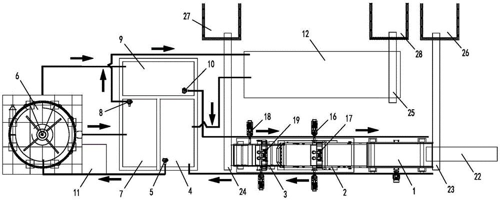
Fig. 1 is a schematic structural diagram of a shield muck lightweight processing system according to an embodiment of the utility model;
FIG. 2 is a control schematic block diagram of a shield muck lightweight processing system according to an embodiment of the utility model;
fig. 3 is a working flow chart of the shield muck lightweight processing system according to the embodiment of the utility model.
In the figure, 1, a vibrating screen, 2, a sand washer, 3, a fine sand recycling machine, 4, a sewage tank, 5, a first slurry pump, 6, a flocculation device, 7, a sludge tank, 8, a second slurry pump, 9, a clean water tank, 10, a clean water pump, 11, a dosing device, 12, a filter pressing device, 13, a controller, 14, a first liquid level sensor, 15, a second liquid level sensor, 16, a third slurry pump, 17, a first cyclone separator, 18, a fourth slurry pump, 19, a second cyclone separator, 20, a metering pump, 21, a flowmeter, 22, a feeding device, 23, a stone conveyor, 24, a sand conveyor, 25, a waste residue conveyor, 27, a stone bin, 28, a sand bin, 29 and a waste residue storage yard.
Detailed Description
The utility model is described in detail below by way of exemplary embodiments. It should be understood, however, that elements, structures and features of one embodiment may be beneficially incorporated in other embodiments without further recitation.
In the description of the present invention, it should be noted that the terms "upper", "lower", "left", "right", "inner", "outer", "top", "bottom", and the like indicate orientations or positional relationships based on positional relationships shown in the drawings, which are merely for convenience of description and simplification of description, but do not indicate or imply that the referred device or element must have a specific orientation, be constructed in a specific orientation, and be operated, and thus, should not be construed as limiting the present invention. Furthermore, the terms "first" and "second" are used for descriptive purposes only and are not to be construed as indicating or implying relative importance.
In the description of the present invention, it should be noted that, unless otherwise explicitly specified or limited, the terms "mounted" and "connected" are to be interpreted broadly, e.g., as a fixed connection, a detachable connection, or an integral connection; they may be connected directly or indirectly through intervening media, or they may be interconnected between two elements. The specific meaning of the above terms in the present invention can be understood in specific cases to those of ordinary skill in the art.
Referring to fig. 1 and 2, the present embodiment provides a shield muck lightweight processing system, including:
a vibratory screening device comprising:
a vibrating screen 1;
the first spraying mechanism is arranged above the vibrating screen 1;
sand washing apparatus, comprising:
a feed inlet of the sand washer 2 is arranged at a sewage outlet of the vibrating screen 1;
the second spraying mechanism is arranged above the sand washer 2;
the fine sand recovery device comprises a fine sand recovery machine 3 provided with a dewatering screen and a bottom groove, wherein the feed end of the dewatering screen is arranged at the outlet of a sand lifting hopper of the sand washer 2, and the bottom groove is communicated with a sewage outlet of the sand washer 2;
the sewage pool 4 is communicated with a sewage outlet of the fine sand recycling machine 3 through a pipeline and is internally provided with a first slurry pump 5;
the water inlet of the flocculation device 6 is communicated with the first slurry pump 5;
the sludge tank 7 is communicated with the sludge outlet of the flocculation device 6 and internally provided with a second sludge pump 8;
the clean water tank 9 is communicated with an overflow port of the flocculation device 6, and is internally provided with a clean water pump 10 which is respectively communicated with the first spraying mechanism and the second spraying mechanism;
the dosing device 11 is communicated with a dosing port of the flocculation device 6;
and a feed inlet of the filter pressing device 12 is communicated with the second slurry pump 8, and a sewage port of the filter pressing device is communicated with the sewage pool 4.
Referring to fig. 2, in order to realize the automatic control of the shield muck, the shield muck lightweight processing system further comprises a control device, wherein the control device comprises a controller 13, and a first liquid level sensor 14 and a second liquid level sensor 15 which are electrically connected with the controller 13, the controller 13 is electrically connected with a vibrating screen 1, a sand washer 2, a fine sand reclaimer 3, a first muck pump 5, a second muck pump 8, a clean water pump 10, a chemical feeding device 11 and a filter pressing device 12, the first liquid level sensor 14 is arranged in the sewage tank 4, and the second liquid level sensor 15 is arranged in the clean water tank 9. In the whole treatment process, full-automatic control is realized through the controller, and the method is simple to operate, safe, reliable and high in treatment efficiency.
With continued reference to fig. 1 and 2, in a specific embodiment, the sand washing apparatus further includes:
the third slurry pump 16 is arranged in a sewage tank of the sand washer 2 and is electrically connected with the controller 13;
and a water inlet of the first cyclone separator 17 is communicated with the third slurry pump 16 through a pipeline, a water outlet of the first cyclone separator is communicated with the second spraying mechanism, and a sand outlet of the first cyclone separator is communicated with a sand lifting hopper of the sand washer 2 and is electrically connected with the controller 13.
And sewage generated by sand washing of the sand washer is pumped into the first cyclone separator from the sewage tank through the third slurry pump, the first cyclone separator performs cyclone separation, separated fine sand is recycled after being dehydrated by the fine sand recycling machine, and the generated sewage enters the second spraying mechanism to be recycled again for fine sand.
With continued reference to fig. 1 and 2, in a specific embodiment, the fine sand recovery device further includes:
the fourth slurry pump 18 is arranged in the bottom groove of the fine sand reclaimer 3 and is electrically connected with the controller 13;
and the second cyclone separator 19 is electrically connected with the controller 13, the water inlet of the second cyclone separator is communicated with the fourth slurry pump 17 through a pipeline, the water outlet of the second cyclone separator is communicated with the sewage tank 4 through a pipeline, and the sand outlet of the second cyclone separator is arranged at the feed end of the dewatering screen.
And pumping the sewage generated by sand washing and fine sand dehydration into a second cyclone separator by a second slurry pump, carrying out cyclone separation by the second cyclone separator, recovering the separated fine sand after the fine sand is dehydrated by a fine sand recovery machine, and enabling the separated sewage to flow into a sewage pool through a pipeline.
Specifically, charge device including hold the medicament add medicine container, with add medicine container intercommunication dosing pump 20, with dosing pump 20 be connected add medicine pipeline and locate the flowmeter 21 in the flocculation device 4, dosing pump 20 and flowmeter 21 with controller 13 electricity is connected, add the medicine pipeline and directly communicate with the medicine mouth that adds of flocculation device 6. The controller controls the metering pump to pump the liquid medicine in the medicine adding container into the flocculation device through the medicine adding pipeline according to the sewage flow detected by the flowmeter.
With continued reference to fig. 1 and 2, in a specific embodiment, the shield muck lightweight processing system further includes a feeding device 22 placed in the stock ground, the feeding device is electrically connected to the controller, and a feeding end of the vibrating screen is disposed at a discharge port of the feeding device. Specifically, the feeding device is a feeding conveyor and is placed on a construction site, shield muck generated on the construction site is conveyed to the vibrating screen, and automatic conveying of the shield muck is achieved.
In order to facilitate conveying the separated stones, sands and waste residues to the corresponding stone bin, sand bin and waste residue storage yard, with reference to fig. 1 and 2, in a specific embodiment, the shield-driven light-weight muck processing system further includes a conveying device electrically connected to the controller 13, where the conveying device includes:
a stone conveyor 23, the feeding end of which is arranged at the discharge port of the vibrating screen 1 and the discharge end of which is arranged above the stone bin 26;
a sand conveyor 24, the feed end of which is arranged at the discharge port of the dewatering screen and the discharge end of which is arranged above the sand silo 27;
and the feed end of the waste residue conveyor 25 is arranged at the discharge port of the filter pressing device 12, and the discharge end of the waste residue conveyor is arranged above the waste residue storage yard 28.
The separated stones are sent into a stone bin through a stone conveyor, the separated sands are sent into a sand bin through a sand conveyor, and the waste residues obtained through filter pressing are sent into a waste residue storage yard through a waste residue conveyor.
Specifically, in this embodiment, the flocculation device employs a flocculation tank, and the filter pressing device employs a filter press.
It should be noted that the treatment system can be directly applied to the operation site, and the separated stones and sands can be directly recycled.
Referring to fig. 3, the work flow of the processing system is as follows:
the shield residual soil is conveyed to a vibrating screen through a feeding device, large-particle-size stones are screened out after being washed and screened through high-pressure spraying, evenly fall on a stone conveyor and enter a stone bin through the stone conveyor. The sand-containing sewage separated by the vibrating screen enters a sand washer for sand washing treatment, the separated coarse sand enters a dewatering screen of a fine sand recycling machine through a sand lifting hopper of the sand washer, and the dewatered sand uniformly falls on a sand material conveying machine and enters a sand storage bin through the sand material conveying machine. And residual sewage containing fine sand in the sand washer is pumped into the first cyclone separator through a third slurry pump, the fine sand separated by the primary cyclone separator enters a sand lifting hopper of the sand washer again, sand dehydrated on a dehydration screen of the fine sand recycling machine enters the sand material conveying machine through the sand lifting hopper of the sand washer and uniformly falls on the sand material conveying machine, the sand material enters a sand storage bin through the sand material conveying machine, and the separated sewage is recycled for sand washing again. And residual fine sand-containing sewage in the sand washer flows into a bottom groove of the fine sand recycling machine through a bottom structure of the sand washer, is pumped into a second cyclone separator through a fourth slurry pump, fine sand separated by primary cyclone falls onto a dewatering screen of the fine sand recycling machine, and the dewatered sand uniformly falls onto a sand material conveying machine and enters a sand bin through the sand material conveying machine, and the separated sewage enters a sewage pool through a pipeline. The first liquid level sensor measures the liquid level of sewage in the effluent water sump, when reaching and setting for the liquid level, by the first sediment stuff pump go into the flocculation device, add the medicament by charge device, the mud of flocculation department of flocculation device discharges into the sludge impoundment through a mud outlet, the clear water in top flows into the clean water basin through overflow mouth through overflow pipeline, recycle is used for using when vibration screening and sand washing. And sludge in the sludge pond enters the filter pressing device through the second slurry pump, sewage after filter pressing is discharged into the sewage pond, clear water is generated through flocculation concentration of the flocculation device again and is used for spraying and cleaning a screen of the vibrating screen and a sand lifting hopper of the sand washer, and a filter cake generated by filter pressing is conveyed to a waste residue storage yard through the waste residue conveyor.
The treatment system has the advantages of reasonable structure and compact layout, realizes the separation of the shield muck into stones and sands for recycling, treats the sewage generated in the separation process, recycles the treated water, and realizes zero emission. The processing process of the whole processing system is fully automatically controlled and completed by the controller, and the automation degree is high.
The above-described embodiments are intended to illustrate rather than to limit the utility model, and any modifications and variations of the present invention are possible within the spirit and scope of the claims.