CN215579929U - Outdoor control cabinet - Google Patents
Outdoor control cabinet Download PDFInfo
- Publication number
- CN215579929U CN215579929U CN202121699794.7U CN202121699794U CN215579929U CN 215579929 U CN215579929 U CN 215579929U CN 202121699794 U CN202121699794 U CN 202121699794U CN 215579929 U CN215579929 U CN 215579929U
- Authority
- CN
- China
- Prior art keywords
- plate
- wall
- cabinet body
- bump
- front plate
- Prior art date
- Legal status (The legal status is an assumption and is not a legal conclusion. Google has not performed a legal analysis and makes no representation as to the accuracy of the status listed.)
- Active
Links
Images

Landscapes
- Patch Boards (AREA)
Abstract
The utility model provides an outdoor control cabinet, which is convenient to radiate heat and avoids the problem that rainwater enters the cabinet body. More than three rows of outer air vents are respectively arranged on the front wall, the rear wall, the left wall and the right wall of the cabinet body; a front plate, a rear plate, a left plate and a right plate are respectively arranged in the cabinet body close to the front wall, the rear wall, the left wall and the right wall, the front plate and the rear plate are respectively and slidably mounted in left and right chutes formed in the top and the bottom of the cabinet body through top and bottom sliding blocks, and the left plate and the right plate are respectively and slidably mounted in front and rear chutes formed in the top and the bottom of the cabinet body through top and bottom sliding blocks; the front plate, the rear plate, the left plate and the right plate are respectively provided with more than three rows of inner ventilation ports, and the inner ventilation ports can respectively correspond to the outer ventilation ports; the front plate inner side surface two ends are respectively provided with a first lug, the rear plate inner side surface two ends are respectively provided with a second lug, the right ends of the front plate and the rear plate are respectively connected through a connecting plate, and the connecting plate is installed at the end part of the motor extending shaft.
Description
Technical Field
The utility model belongs to the field of control cabinets, and particularly relates to an outdoor control cabinet.
Background
The control cabinet is formed by assembling switch equipment, measuring instruments, protective electrical appliances and auxiliary equipment in a closed or semi-closed metal cabinet or on a screen according to the electrical wiring requirements, and the arrangement of the control cabinet meets the requirements of normal operation of an electric power system, is convenient to overhaul and does not endanger the safety of people and surrounding equipment. In normal operation, the circuit can be switched on or off by means of a manual or automatic switch. When the fault or abnormal operation occurs, the circuit is cut off or an alarm is given by the aid of the protective electric appliance. The measuring instrument can display various parameters in operation, and can also adjust some electrical parameters to prompt or send out signals for deviation from normal working state. It is commonly used in various power generation, distribution and transformation substations.
At present outdoor electric control cabinet is relative encapsulated situation to set up a large amount of heat-radiating equipment in the switch board, increased energy resource consumption, consequently can set up the bleeder vent on the switch board a bit, but in case rain, the easy rainwater that advances of ventilative mouthful has increased the risk of circuit short circuit in the switch board again.
Disclosure of Invention
In order to solve the problem that the outdoor control cabinet cannot give consideration to both heat dissipation and rain prevention, the utility model provides an outdoor control cabinet, which is convenient to dissipate heat and simultaneously avoids the problem that rainwater enters the cabinet body.
In order to achieve the purpose, the utility model is realized by the following technical scheme:
the utility model provides a be used for open air switch board, its includes the cabinet body, its characterized in that: more than three rows of outer air vents are respectively arranged on the front wall, the rear wall, the left wall and the right wall of the cabinet body; a front plate, a rear plate, a left plate and a right plate are respectively arranged in the cabinet body close to the front wall, the rear wall, the left wall and the right wall, the front plate and the rear plate are respectively and slidably mounted in left and right chutes formed in the top and the bottom of the cabinet body through top and bottom sliding blocks, and the left plate and the right plate are respectively and slidably mounted in front and rear chutes formed in the top and the bottom of the cabinet body through top and bottom sliding blocks; the front plate, the rear plate, the left plate and the right plate are respectively provided with more than three rows of inner ventilation ports, and the inner ventilation ports can respectively correspond to the outer ventilation ports; the two ends of the inner side surface of the front plate are respectively provided with a first lug, the two ends of the inner side surface of the rear plate are respectively provided with a second lug, the right ends of the front plate and the rear plate are respectively connected through a connecting plate, and the connecting plate is arranged at the end part of a motor extending shaft; when an extension shaft of the motor extends out, the front plate and the rear plate move leftwards, the first lug pushes the left plate and the right plate to move forwards, and the inner ventilation port and the outer ventilation port are staggered; when the extension shaft of the motor retracts, the front plate and the rear plate move rightwards, the second protruding block pushes the left plate and the right plate to move backwards, and at the moment, the inner ventilation opening corresponds to the outer ventilation opening.
It is further characterized in that:
the top of the cabinet body is provided with a triangular top, and a limiting rod penetrates through the bottom of the triangular top and is installed at the top of the cabinet body; the front plate and the rear plate are respectively provided with a third bump, the contact surface of the third bump is an inclined arc surface, a convex rod is arranged in the triangular top, and when the front plate and the rear plate drive the third bump to move leftwards, the convex rod moves from the high position of the third bump to the low position of the third bump to drive the triangular top to fall; when the front plate and the rear plate drive the third bump to move rightwards, the convex rod moves from the low position of the third bump to the high position of the third bump to drive the triangular top to lift;
the two lines of the inner ventilating openings and the two lines of the outer ventilating openings are provided with inward concave cambered surfaces.
The utility model has the beneficial effects that: in sunny days, the extension shaft of the motor retracts, the inner ventilating opening corresponds to the outer ventilating opening, and the triangular top is lifted up, so that heat dissipation and ventilation are facilitated; during rainy day, the projecting shaft of motor stretches out, and interior ventilative mouthful staggers with outer ventilative mouth, and the triangle top falls, avoids in the rainwater gets into the switch board, has realized compromising heat dissipation and rainproof effect, is fit for being applied to the open air.
Drawings
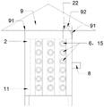
FIG. 1 is a schematic view of the overall structure of the motor of the present invention with the extension shaft extended;
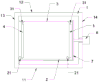
FIG. 2 is a schematic top view of the internal structure of the cabinet with the motor protruding shaft extended;
FIG. 3 is a schematic view of the overall structure of the motor of the present invention with the extension shaft retracted;
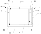
FIG. 4 is a schematic top view of the internal structure of the cabinet with the motor extension shaft retracted according to the present invention;
in the figure: 1, a cabinet body; 11 a front wall; 12 a rear wall; 13 a left wall; 14 a right wall; 15 an outer gas permeable port; 2, a front plate; 21 a first bump; 22 a third bump; 3, a rear plate; 31 a second bump; 4, a left plate; 5, a right plate; 6, an inner ventilation opening; 7 connecting plates; 8, a motor; 9 triangular top; 91 a limiting rod; 92 protruding rod.
Detailed Description
For the purpose of enhancing the understanding of the present invention, the present invention will be described in further detail with reference to the accompanying drawings and examples, which are provided for the purpose of illustration only and are not intended to limit the scope of the present invention.
A control cabinet used outdoors is provided, wherein more than three rows of outer air vents 15 are respectively arranged on a front wall 11, a rear wall 12, a left wall 13 and a right wall 14 of a cabinet body 1; a front plate 2, a rear plate 3, a left plate 4 and a right plate 5 are respectively arranged in the cabinet body 1 close to the front wall 11, the rear wall 12, the left wall 13 and the right wall 14, the front plate 2 and the rear plate 3 are respectively installed in left and right chutes formed in the top and the bottom of the cabinet body 1 through sliding blocks at the top and the bottom in a sliding manner, and the left plate 4 and the right plate 5 are respectively installed in front and rear chutes formed in the top and the bottom of the cabinet body 1 through sliding blocks at the top and the bottom in a sliding manner; the front plate 2, the rear plate 3, the left plate 4 and the right plate 5 are respectively provided with more than three rows of inner ventilation ports 6, and the inner ventilation ports 6 can respectively correspond to the outer ventilation ports 15; the two ends of the inner side surface of the front plate 2 are respectively provided with a first lug 21, the two ends of the inner side surface of the rear plate 3 are respectively provided with a second lug 31, the right ends of the front plate 2 and the rear plate 3 are respectively connected through a connecting plate 7, and the connecting plate 7 is arranged at the end part of the extending shaft of the motor 8; when the extension shaft of the motor 8 extends out, the front plate 2 and the rear plate 3 move leftwards, the first lug 21 pushes the left plate 4 and the right plate 5 to move forwards, and the inner ventilation opening 6 and the outer ventilation opening 15 are staggered; when the extending shaft of the motor 8 retracts, the front plate 2 and the rear plate 3 move rightwards, the second lug 31 pushes the left plate 4 and the right plate 5 to move backwards, and the inner ventilation opening 6 corresponds to the outer ventilation opening 15.
The top of the cabinet body 1 is provided with a triangular top 9, and the limiting rod 91 passes through the bottom of the triangular top 9 and is installed at the top of the cabinet body 1; the top parts of the front plate 2 and the rear plate 3 are respectively provided with a third bump 22, the contact surface of the third bump 22 is an inclined arc surface, a convex rod 92 is arranged in the triangular top 9, and when the front plate 2 and the rear plate 3 drive the third bump 22 to move leftwards, the convex rod 92 moves from the high position of the third bump 22 to the low position of the third bump 22 to drive the triangular top 9 to fall; when the front plate 2 and the rear plate 3 drive the third bump 22 to move rightwards, the convex rod 92 moves from the lower part of the third bump 22 to the higher part of the third bump 22 to drive the triangular top 9 to lift; an inward concave cambered surface is arranged between the two lines of inner air vents 6 and the two lines of outer air vents 15.
The utility model has the beneficial effects that: in sunny days, the extension shaft of the motor 8 retracts, the inner ventilating opening 6 corresponds to the outer ventilating opening 15, and the triangular top 9 is lifted, so that heat dissipation and ventilation are facilitated; during rainy day, motor 8's projecting shaft stretches out, and interior ventilative mouthful 6 staggers with outer ventilative mouth 15, and the descending of triangle top 9 has been realized taking into account heat dissipation and rainproof effect in avoiding the rainwater to get into the switch board, is fit for being applied to the open air.
Claims (3)
1. The utility model provides a be used for open air switch board, its includes the cabinet body, its characterized in that: more than three rows of outer air vents are respectively arranged on the front wall, the rear wall, the left wall and the right wall of the cabinet body; a front plate, a rear plate, a left plate and a right plate are respectively arranged in the cabinet body close to the front wall, the rear wall, the left wall and the right wall, the front plate and the rear plate are respectively and slidably mounted in left and right chutes formed in the top and the bottom of the cabinet body through top and bottom sliding blocks, and the left plate and the right plate are respectively and slidably mounted in front and rear chutes formed in the top and the bottom of the cabinet body through top and bottom sliding blocks; the front plate, the rear plate, the left plate and the right plate are respectively provided with more than three rows of inner ventilation ports, and the inner ventilation ports can respectively correspond to the outer ventilation ports; the two ends of the inner side surface of the front plate are respectively provided with a first lug, the two ends of the inner side surface of the rear plate are respectively provided with a second lug, the right ends of the front plate and the rear plate are respectively connected through a connecting plate, and the connecting plate is arranged at the end part of a motor extending shaft; when an extension shaft of the motor extends out, the front plate and the rear plate move leftwards, the first lug pushes the left plate and the right plate to move forwards, and the inner ventilation port and the outer ventilation port are staggered; when the extension shaft of the motor retracts, the front plate and the rear plate move rightwards, the second protruding block pushes the left plate and the right plate to move backwards, and at the moment, the inner ventilation opening corresponds to the outer ventilation opening.
2. A control cabinet for outdoor use according to claim 1, wherein: the top of the cabinet body is provided with a triangular top, and a limiting rod penetrates through the bottom of the triangular top and is installed at the top of the cabinet body; the front plate and the rear plate are respectively provided with a third bump, the contact surface of the third bump is an inclined arc surface, a convex rod is arranged in the triangular top, and when the front plate and the rear plate drive the third bump to move leftwards, the convex rod moves from the high position of the third bump to the low position of the third bump to drive the triangular top to fall; when the front plate and the rear plate drive the third bump to move rightwards, the convex rod moves from the lower part of the third bump to the high part of the third bump to drive the triangular top to lift.
3. A control cabinet for outdoor use according to claim 2, wherein: the two lines of the inner ventilating openings and the two lines of the outer ventilating openings are provided with inward concave cambered surfaces.
Priority Applications (1)
| Application Number | Priority Date | Filing Date | Title |
|---|---|---|---|
| CN202121699794.7U CN215579929U (en) | 2021-07-26 | 2021-07-26 | Outdoor control cabinet |
Applications Claiming Priority (1)
| Application Number | Priority Date | Filing Date | Title |
|---|---|---|---|
| CN202121699794.7U CN215579929U (en) | 2021-07-26 | 2021-07-26 | Outdoor control cabinet |
Publications (1)
| Publication Number | Publication Date |
|---|---|
| CN215579929U true CN215579929U (en) | 2022-01-18 |
Family
ID=79828269
Family Applications (1)
| Application Number | Title | Priority Date | Filing Date |
|---|---|---|---|
| CN202121699794.7U Active CN215579929U (en) | 2021-07-26 | 2021-07-26 | Outdoor control cabinet |
Country Status (1)
| Country | Link |
|---|---|
| CN (1) | CN215579929U (en) |
-
2021
- 2021-07-26 CN CN202121699794.7U patent/CN215579929U/en active Active
Similar Documents
| Publication | Publication Date | Title |
|---|---|---|
| CN204651719U (en) | One is lowered the temperature power distribution cabinet automatically | |
| CN208461248U (en) | A kind of outdoor low-voltage distribution cabinet of anti-heavy rain | |
| CN215579929U (en) | Outdoor control cabinet | |
| CN204259345U (en) | A kind of electric machine controller assembly apparatus of the electri forklift with tooth-like heat radiation | |
| CN213185122U (en) | Intelligent electronic control device | |
| CN207135128U (en) | A kind of energy saver of communication switchboard | |
| CN203180376U (en) | High-temperature-resisting corrosion-resisting power distribution box | |
| CN212485820U (en) | Heat dissipation switch board | |
| CN201754474U (en) | Distribution box of power equipment | |
| CN211556616U (en) | Electrical control cabinet | |
| CN114530782A (en) | Storage battery constant temperature control cabinet based on electrical control system | |
| CN210490153U (en) | Block terminal convenient to heat dissipation and ventilation | |
| CN215378008U (en) | Electrical control cabinet with short-circuit prevention unit for milling machine | |
| CN208094963U (en) | A kind of high performance communication cabinet | |
| CN212033535U (en) | Floor type distribution box | |
| CN205355628U (en) | Solar energy switch board | |
| CN214379595U (en) | Novel distribution equipment switch board | |
| CN216450945U (en) | Dustproof radiating low-voltage switchgear | |
| CN215645751U (en) | High-voltage outlet cabinet with temperature monitoring function | |
| CN219761807U (en) | Over-temperature relay protection device | |
| CN220368356U (en) | Control cabinet with adjustable heat radiation structure | |
| CN210297006U (en) | Intelligent low-voltage comprehensive distribution box | |
| CN213341344U (en) | Electrical control cabinet heat radiation structure | |
| CN214798232U (en) | Novel environmental protection low pressure power distribution box | |
| CN214958012U (en) | Electric control cabinet for oil and gas well |
Legal Events
| Date | Code | Title | Description |
|---|---|---|---|
| GR01 | Patent grant | ||
| GR01 | Patent grant |