CN215573696U - Optical fiber jumper wire detection device - Google Patents
Optical fiber jumper wire detection device Download PDFInfo
- Publication number
- CN215573696U CN215573696U CN202121923598.3U CN202121923598U CN215573696U CN 215573696 U CN215573696 U CN 215573696U CN 202121923598 U CN202121923598 U CN 202121923598U CN 215573696 U CN215573696 U CN 215573696U
- Authority
- CN
- China
- Prior art keywords
- optical fiber
- detection device
- box body
- fiber jumper
- fixedly connected
- Prior art date
- Legal status (The legal status is an assumption and is not a legal conclusion. Google has not performed a legal analysis and makes no representation as to the accuracy of the status listed.)
- Active
Links
Images


Abstract
The utility model discloses an optical fiber jumper wire detection device, which comprises a box body, wherein the back surface of the box body is provided with a protection mechanism, the protection mechanism comprises a handle, a cover plate, a placing groove, a mounting groove, a rotating rod, a mounting block and a jumper wire interface, the center of the back surface of the box body is provided with the mounting groove, the jumper wire interface is mounted in a notch of the mounting groove, the rotating rod is fixedly mounted at two sides in the mounting groove, the mounting block is fixedly mounted at two ends of the surface of the rotating rod, and the cover plate is fixedly mounted at the top of the mounting block; the parts of the protection mechanism are arranged and used in a matched manner, so that a jumper wire interface on the protection mechanism is protected, the loss is reduced, and the protection performance of the protection mechanism is improved; parts through setting up buffer gear and then the cooperation is used to the effect of loss tester protection is inserted in the improvement, and also through parts wherein, and then improves the effect of buffering protection.
Description
Technical Field
The utility model relates to the technical field of optical fiber jumpers, in particular to an optical fiber jumper detection device.
Background
Optical fiber jumpers are used to patch wires from equipment to fiber optic cabling links. The optical fiber protective layer has a thicker protective layer, is generally used for connection between an optical transceiver and a terminal box, and is applied to the fields of optical fiber communication systems, optical fiber access networks, optical fiber data transmission, local area networks and the like.
At present, a jumper wire detection interface end on the existing optical fiber jumper wire detector is usually directly exposed outside and is easily impacted by foreign objects, so that damage is caused and unnecessary loss is caused; the existing jumper wire detector has poor protection performance, so that the jumper wire detector is easy to be impacted at one end, and further internal elements are directly damaged, and further economic loss is caused; and because long-time use it, easily make its components and parts produce high temperature, easily make its life reduce, increase the loss.
SUMMERY OF THE UTILITY MODEL
Aiming at the technical problems in the prior art, the utility model provides the optical fiber jumper wire detection device, and the components of the protection mechanism are arranged and further matched for use, so that the jumper wire interface on the optical fiber jumper wire detection device is protected, the loss is reduced, and the protection performance is improved; parts through setting up buffer gear and then the cooperation is used to the effect of loss tester protection is inserted in the improvement, and also through parts wherein, and then improves the effect of buffering protection.
The technical scheme for solving the technical problems is as follows:
optical fiber wire jumper detection device, the power distribution box comprises a box body, the back of box is equipped with protection machanism, protection machanism includes handle, apron, standing groove, mounting groove, bull stick, installation piece and wire jumper interface, the mounting groove is seted up at the back center of box, the notch internally mounted wire jumper interface of mounting groove, the inside both sides fixed mounting of mounting groove has the bull stick, the surperficial both ends fixed mounting of bull stick has the installation piece, the top fixed mounting of installation piece has the apron, the surface card of apron establishes at least three group's standing grooves, the top fixed mounting of apron has the handle.
On the basis of the technical scheme, the utility model can be further improved as follows.
Further, the display screen is fixedly installed at one end of the front face of the box body, and the switch is fixedly installed at the other end of the front face of the box body.
Further, the inside center of box is equipped with inserts the return loss tester, the both sides fixed mounting who inserts the return loss tester has the mounting bracket.
Further, the bottom of inserting the return loss tester is fixed in the box through an auxiliary supporting rod, and the top of inserting the return loss tester is fixedly connected with a buffer board.
Furthermore, the top center fixedly connected with head rod of buffer board, the top both ends fixedly connected with second connecting rod of buffer board, the other end fixed connection second buffer spring of head rod intercommunication protective housing inside, the second connecting rod communicates in the first buffer spring of the other end fixed connection of second fixed block inside.
Further, the protective shell and the second fixing block are fixed above the interior of the box body.
Further, insert one side fixed mounting that decreases the tester back and have first fixed block, the inside below of first fixed block is equipped with the installation region, the one end fixed mounting of installation region has the absorber plate, the other end of installation region passes through the fixed heat dissipation fan of branch.
Further, one side fixed connection cooling tube of heat dissipation fan, the other end fixed connection of cooling tube is in the thermovent, the thermovent is fixed in the back of box.
Compared with the prior art, the technical scheme of the application has the following beneficial technical effects:
the handle is arranged at the top of the cover plate, so that the cover plate can be conveniently opened; the installation groove is formed in the back of the box body, so that the jumper wire interface is conveniently installed in the installation groove; the jumper wire interface is arranged in the mounting groove, so that the optical fiber jumper wire can be conveniently detected; the placing groove is formed in the cover plate, so that the jumper wire interface is conveniently sealed and protected; the collision is avoided, and further loss is avoided; the rotating rod is arranged in the mounting groove, so that the cover plate on the rotating rod can be conveniently turned over, and the mounting block is fixedly connected with the cover plate, so that the cover plate is fixedly supported; the parts of the protection mechanism are matched for use, so that a jumper wire interface on the protection mechanism is protected, the loss is reduced, and the protection performance of the protection mechanism is improved;
The auxiliary supporting rod is arranged, so that the insertion return loss tester can be supported in an auxiliary fixing mode and can be protected in an auxiliary protection mode; through the part and then the cooperation use of buffer gear more than setting up to the improvement is gone on the effect protected to inserting back to decrease the tester in the box, and also through part wherein, and then improves the effect of buffering protection.
Drawings
FIG. 1 is a schematic structural diagram of a case according to the present invention;
FIG. 2 is a schematic view of the back structure of the case of the present invention;
FIG. 3 is a schematic view of a main sectional structure of the case of the present invention;
FIG. 4 is a left side sectional view of the case of the present invention;
fig. 5 is a schematic structural diagram of a buffer mechanism of the present invention.
In the drawings, the components represented by the respective reference numerals are listed below: 1. a box body; 2. a display screen; 3. a switch; 4. a handle; 401. a cover plate; 402. a placement groove; 403. mounting grooves; 404. a rotating rod; 405. mounting blocks; 406. a jumper wire interface; 5. a heat dissipation port; 501. a radiating pipe; 502. a heat dissipation fan; 503. a first fixed block; 504. a heat absorbing plate; 6. a mounting frame; 601. inserting a return loss tester; 602. an auxiliary support bar; 7. a buffer plate; 701. a first connecting rod; 702. a second connecting rod; 703. a second fixed block; 704. a first buffer spring; 705. a second buffer spring.
Detailed Description
The principles and features of the present invention will be described with reference to the accompanying drawings, which are provided for illustration only and are not intended to limit the scope of the utility model. All other embodiments, which can be derived by a person skilled in the art from the embodiments given herein without making any creative effort, shall fall within the protection scope of the present invention.
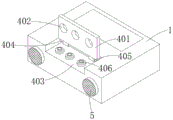
The utility model provides an optical fiber jumper wire detection device, an optical fiber jumper wire detection device and an optical fiber jumper wire detection device shown in figures 1-5, which comprise a box body 1, wherein the back of the box body 1 is provided with a protection mechanism, the protection mechanism comprises a handle 4, a cover plate 401, a placing groove 402, a mounting groove 403, a rotating rod 404, a mounting block 405 and a jumper wire interface 406, and the protection mechanism is matched with the parts of the protection mechanism for use, so that the jumper wire interface 406 is protected, the loss is reduced, and the protection performance is improved; the installation groove 403 is formed in the center of the back of the box body 1, the installation groove 403 mainly plays a role in facilitating installation of a jumper interface 406 in the installation groove 403, the jumper interface 406 is installed inside a notch of the installation groove 403, rotating rods 404 are fixedly installed on two sides inside the installation groove 403, installation blocks 405 are fixedly installed at two ends of the surface of each rotating rod 404, a cover plate 401 is fixedly installed at the top of each installation block 405, at least three groups of placing grooves 402 are clamped on the surface of each cover plate 401, a handle 4 is fixedly installed at the top of each cover plate 401, the cover plates 401 are turned upwards by taking the handle 4, the rotating rods 404 in the installation grooves 403 drive the cover plates 401 to be turned and opened, and the placing grooves 402 in the cover plates 401 are separated from the jumper interfaces 406, so that the optical fiber jumpers can be detected conveniently, and qualified and unqualified detection is achieved; and the jumper wire interface 406 is also protected by the cooperation of the protection mechanisms.
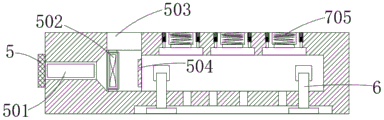
The positive one end fixed mounting of box 1 has display screen 2, display screen 2 mainly makes the data of optic fibre wire jumper when detecting carry out the effect that shows on it, the positive other end fixed mounting of box 1 has switch 3, the inside center of box 1 is equipped with inserts back and decreases tester 601, the model of inserting back and decreasing tester 601 is SGJ1-6900, mainly play and detect qualified and unqualified effect to the optic fibre wire jumper, the both sides fixed mounting who inserts back and decreases tester 601 has mounting bracket 6, mounting bracket 6 mainly carries out the effect of fixed stay to inserting back and decreasing tester, insert back and decrease the inside that the bottom of tester 601 is fixed in box 1 through auxiliary stay pole 602, insert back and decrease the top fixed connection buffer board 7 of tester 601.
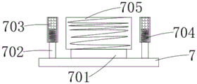
As shown in fig. 3, 4, and 5, a first connecting rod 701 is fixedly connected to the center of the top of the buffer plate 7, second connecting rods 702 are fixedly connected to two ends of the top of the buffer plate 7, the first connecting rod 701 is communicated with a second buffer spring 705 which is fixedly connected to the other end inside the protective shell, the second connecting rod 702 is communicated with a first buffer spring 704 which is fixedly connected to the other end inside the second fixed block 703, the protective shell and the second fixed block 703 are fixed to the upper portion inside the box body 1, and the buffer plate 7 therein is pressed, so that the buffer plate 7 drives the first connecting rod 701 and the second connecting rod 702 thereon to press down, and further the first connecting rod 701 and the second connecting rod 702 drive the first buffer spring 704 and the second buffer spring 705 thereon to perform downward buffering, thereby reducing the pressure during collision and reducing the damage thereon.
In addition, the utility model also fixedly installs a first fixed block 503 (as shown in fig. 4) at one side of the insertion loss tester 601, an installation area is arranged at the lower part inside the first fixed block 503, one end of the installation area is fixedly installed with a heat absorbing plate 504, the other end of the installation area is fixed with a heat dissipating fan 502 through a support rod, one side of the heat dissipating fan 502 is fixedly connected with a heat dissipating pipe 501, the other end of the heat dissipating pipe 501 is fixedly connected with a heat dissipating port 5, the heat dissipating port 5 is fixed at the back of the box body 1, because the insertion return loss tester 601 is used for a long time, the internal components of the insertion return loss tester 601 are easy to generate high temperature, at the moment, the heat absorption plate 504 on the insertion return loss tester 601 absorbs heat, then, the heat dissipation fan 502 is started to absorb heat and dissipate heat, so that the absorbed heat is discharged into the heat dissipation pipe 501, and finally discharged to the outside from the heat dissipation port 5 on the heat dissipation pipe, thereby prolonging the service life of the return loss tester 601 inserted on the heat dissipation pipe.
When the jumper wire detection device is used, the cover plate 401 is turned upwards by taking the handle 4, so that the rotating rod 404 in the mounting groove 403 drives the cover plate 401 to be turned and opened, and the placing groove 402 on the cover plate 401 is separated from the jumper wire interface 406, so that the optical fiber jumper wire is detected, and the optical fiber jumper wire detection device has the function of detecting whether the optical fiber jumper wire is qualified or not; the jumper wire interface 406 is also protected by the protection mechanism used in a matching way; when the box body 1 is collided, the buffer plate 7 in the box body is extruded, so that the buffer plate 7 drives the first connecting rod 701 and the second connecting rod 702 on the buffer plate to press down, and then the first connecting rod 701 and the second connecting rod 702 drive the first buffer spring 704 and the second buffer spring 705 on the first connecting rod to buffer downwards, the pressure during collision is reduced, and the damage on the first buffer spring is also reduced.
The above description is only for the purpose of illustrating the preferred embodiments of the present invention and is not to be construed as limiting the utility model, and any modifications, equivalents, improvements and the like that fall within the spirit and principle of the present invention are intended to be included therein.
Claims (8)
1. Optical fiber jumper detection device, including box (1), its characterized in that, the back of box (1) is equipped with protection machanism, protection machanism includes handle (4), apron (401), standing groove (402), mounting groove (403), bull stick (404), installation piece (405) and wire jumper interface (406), mounting groove (403) are seted up at the back center of box (1), notch internally mounted wire jumper interface (406) of mounting groove (403), the inside both sides fixed mounting of mounting groove (403) has bull stick (404), the surperficial both ends fixed mounting of bull stick (404) has installation piece (405), the top fixed mounting of installation piece (405) has apron (401), the surface card of apron (401) establishes at least three group standing grooves (402), the top fixed mounting of apron (401) has handle (4).
2. The optical fiber jumper detection device according to claim 1, wherein a display screen (2) is fixedly mounted at one end of the front surface of the box body (1), and a switch (3) is fixedly mounted at the other end of the front surface of the box body (1).
3. The optical fiber jumper detection device according to claim 1, wherein an insertion return loss tester (601) is arranged in the center of the interior of the box body (1), and mounting frames (6) are fixedly mounted on two sides of the insertion return loss tester (601).
4. The optical fiber jumper detection device according to claim 3, wherein the bottom of the insertion return loss tester (601) is fixed inside the box body (1) through an auxiliary support rod (602), and the top of the insertion return loss tester (601) is fixedly connected with a buffer plate (7).
5. The optical fiber jumper detection device according to claim 4, wherein a first connecting rod (701) is fixedly connected to the center of the top of the buffer plate (7), second connecting rods (702) are fixedly connected to two ends of the top of the buffer plate (7), the first connecting rod (701) is communicated with a second buffer spring (705) fixedly connected to the other end inside the protective shell, and the second connecting rod (702) is communicated with a first buffer spring (704) fixedly connected to the other end inside the second fixed block (703).
6. The optical fiber jumper detection device according to claim 5, wherein the protective shell and the second fixing block (703) are fixed above the inside of the box body (1).
7. The optical fiber jumper detection device according to claim 3, wherein a first fixing block (503) is fixedly installed on one side of the insertion and return loss tester (601), an installation area is arranged below the inside of the first fixing block (503), a heat absorption plate (504) is fixedly installed at one end of the installation area, and a heat dissipation fan (502) is fixed at the other end of the installation area through a support rod.
8. The optical fiber jumper wire detecting device according to claim 7, wherein one side of the heat dissipating fan (502) is fixedly connected with a heat dissipating pipe (501), the other end of the heat dissipating pipe (501) is fixedly connected with a heat dissipating port (5), and the heat dissipating port (5) is fixed on the back of the box body (1).
Priority Applications (1)
| Application Number | Priority Date | Filing Date | Title |
|---|---|---|---|
| CN202121923598.3U CN215573696U (en) | 2021-08-16 | 2021-08-16 | Optical fiber jumper wire detection device |
Applications Claiming Priority (1)
| Application Number | Priority Date | Filing Date | Title |
|---|---|---|---|
| CN202121923598.3U CN215573696U (en) | 2021-08-16 | 2021-08-16 | Optical fiber jumper wire detection device |
Publications (1)
| Publication Number | Publication Date |
|---|---|
| CN215573696U true CN215573696U (en) | 2022-01-18 |
Family
ID=79836315
Family Applications (1)
| Application Number | Title | Priority Date | Filing Date |
|---|---|---|---|
| CN202121923598.3U Active CN215573696U (en) | 2021-08-16 | 2021-08-16 | Optical fiber jumper wire detection device |
Country Status (1)
| Country | Link |
|---|---|
| CN (1) | CN215573696U (en) |
-
2021
- 2021-08-16 CN CN202121923598.3U patent/CN215573696U/en active Active
Similar Documents
| Publication | Publication Date | Title |
|---|---|---|
| CN210328421U (en) | Computer room server rack with cooling body | |
| CN112512274A (en) | Energy-saving outdoor electronic information anti-jamming device | |
| CN215573696U (en) | Optical fiber jumper wire detection device | |
| CN208210173U (en) | A kind of protective device of outdoor separated wireless communication base station | |
| CN209517741U (en) | A kind of computer application wireless security monitoring device | |
| CN217181569U (en) | Control system for improving ETC lane interference | |
| CN210807500U (en) | Display device for monitoring system | |
| CN211792660U (en) | Underground industrial internet 5G communication equipment protection device | |
| CN210042027U (en) | Optical cable intelligence on-line monitoring system | |
| CN209802541U (en) | device of quick examination body temperature of thermal imaging | |
| CN218446092U (en) | Optical fiber module | |
| CN219107938U (en) | Communication equipment protective housing | |
| CN113451895A (en) | Distribution network information management system and device integrating multiple data architectures | |
| CN208805598U (en) | A kind of communication engineering optical fiber commuting case | |
| CN217506198U (en) | Packaging shell for optical module | |
| CN216121452U (en) | Power distribution cabinet of thing networking | |
| CN215641941U (en) | Light collecting coupler | |
| CN219759826U (en) | Battery pack with battery protection component | |
| CN216053700U (en) | LED display screen with anti-collision structure | |
| CN218735719U (en) | Be applied to comprehensive information processing board of four eyes glasses of intelligence AR | |
| CN211263868U (en) | Optical module with protection function | |
| CN217692240U (en) | Special shock attenuation heat dissipation installing support of switch board | |
| CN216120691U (en) | 5G capacitor coaxial power divider | |
| CN218041551U (en) | Security protection camera waterproof case | |
| CN216852201U (en) | Protective structure for switch |
Legal Events
| Date | Code | Title | Description |
|---|---|---|---|
| GR01 | Patent grant | ||
| GR01 | Patent grant |