CN215564416U - Combined template for pouring concrete inclined roof - Google Patents
Combined template for pouring concrete inclined roof Download PDFInfo
- Publication number
- CN215564416U CN215564416U CN202122042047.2U CN202122042047U CN215564416U CN 215564416 U CN215564416 U CN 215564416U CN 202122042047 U CN202122042047 U CN 202122042047U CN 215564416 U CN215564416 U CN 215564416U
- Authority
- CN
- China
- Prior art keywords
- pull rod
- supporting
- template
- upright post
- support
- Prior art date
- Legal status (The legal status is an assumption and is not a legal conclusion. Google has not performed a legal analysis and makes no representation as to the accuracy of the status listed.)
- Active
Links
Images


Abstract
The utility model relates to the technical field of building pouring, in particular to a combined template for pouring a concrete pitched roof, which comprises top plate template supporting units, wherein a transverse pull rod is arranged between the top plate template supporting units, a combined top plate template is arranged on the upper side of each top plate template supporting unit, each top plate template supporting unit comprises a supporting upright post, a supporting diagonal rod, a middle pull rod, an upper side reinforcing pull rod and a supporting ejector rod, a bottom mounting plate is arranged at the lower end part of the supporting upright post, a supporting diagonal rod is arranged on the left side of the supporting upright post, a middle pull rod is arranged on the left side of the supporting upright post, an upper side reinforcing pull rod is arranged on the left side of the supporting upright post and positioned on the upper side of the middle pull rod, connecting hinge seats are arranged at the left side of the supporting upright post and connected with the middle pull rod and the upper side reinforcing pull rod, pull rod mounting sleeves are arranged in the middles of the front side and the back sides of the supporting upright post, overall structure is simple, convenient to use, and stability and practicality are higher.
Description
Technical Field
The utility model relates to the technical field of building pouring, in particular to a combined template for pouring a concrete pitched roof.
Background
The inclined roof represents the design style of the traditional Chinese building from ancient to present, leads the style of the design of the traditional Chinese building, but because of the single and the insufficient of the technological level of the ancient building materials, most of the traditional Chinese buildings mainly adopt a brick-wood structure, especially the sloping roof building with the traditional Chinese style, has the representative style of being built in the Ming dynasty, the drum building in Fengyang county and the drum building in Nanjing, and along with the progress of the technology and the diversification of the building materials, especially the introduction of cement, the inclined roof with a reinforced concrete structure gradually replaces the traditional wood structure to form a novel building design style, and when the concrete inclined roof is poured, a template is usually used for supporting the poured concrete.
The existing pouring template usually adopts common plywood, and a supporting structure usually adopts square timber, so that the time consumption of the installation of the template is long, the service life of a wooden material is short, and wood is wasted, so that the problem is solved by the combined template for pouring the concrete pitched roof.
SUMMERY OF THE UTILITY MODEL
The utility model aims to provide a combined template for pouring a concrete pitched roof, which aims to solve the problems in the background technology.
In order to achieve the purpose, the utility model provides the following technical scheme:
the utility model provides a built-up plate that oblique roofing of concrete was pour, includes roof template supporting unit, install horizontal pull rod between the roof template supporting unit, the built-up roof template is installed to the upside of roof template supporting unit.
As a preferable scheme of the utility model, the top plate formwork supporting unit comprises a supporting upright post, a supporting diagonal rod, a middle pull rod, an upper reinforcing pull rod and a supporting ejector rod, wherein a bottom mounting plate is mounted at the lower end part of the supporting upright post, the supporting diagonal rod is arranged on the left side of the supporting upright post, the middle pull rod is mounted at the left upper side of the supporting upright post, the upper reinforcing pull rod is mounted at the left side of the supporting upright post and positioned at the upper side of the middle pull rod, connecting hinge seats are mounted at the left side of the supporting upright post and connected with the middle pull rod and the upper reinforcing pull rod, pull rod mounting sleeves are mounted at the middle parts of the front side and the rear side of the supporting upright post, and the supporting ejector rod is mounted at the upper end part of the supporting upright post.
As a preferable scheme of the utility model, transverse pull rods are symmetrically arranged up and down between adjacent supporting diagonal rods, pull rod installation sleeves are arranged at the front side and the rear side of each supporting diagonal rod and at positions corresponding to the transverse pull rods, connecting hinge seats are arranged at the bottom surfaces of the supporting diagonal rods and at the joints with the middle pull rod and the upper side reinforcing pull rod, bolts are arranged at the two ends of the middle pull rod and the upper side reinforcing pull rod and at the joints with the connecting hinge seats, and the supporting upright columns, the supporting diagonal rods, the middle pull rod, the upper side reinforcing pull rod and the supporting ejector rods are all made of thin-wall steel pipes.
In a preferable scheme of the utility model, a bolt hole is formed in the middle of the pull rod mounting sleeve, and mounting holes are formed at corners of the base surface of the bottom mounting plate.
As a preferable scheme of the utility model, the structure and the size of the end part of the transverse pull rod are matched with those of the pull rod mounting sleeve, and the transverse pull rod is connected with the pull rod mounting sleeve through a bolt.
As a preferable aspect of the present invention, the top plate formwork support units are symmetrically provided in plural groups.
As a preferable scheme of the present invention, the combination top plate formwork includes an inclined surface supporting formwork and a top supporting formwork, and the top supporting formwork is transversely installed at an upper side end of the inclined surface supporting formwork.
According to the preferable scheme of the utility model, the inclined plane supporting template and the top supporting template are formed by combining a plurality of steel frame veneers, and are installed through bolts.
Compared with the prior art, the utility model has the beneficial effects that:
according to the utility model, the roof template supporting units are mostly made of thin-wall steel pipes, so that the service life of the device is longer, the overall supporting stability and safety are stronger, meanwhile, the device is simple and convenient to assemble and disassemble due to the fact that the roof template supporting units are mostly made of thin-wall steel pipes, and the combined roof template is made of steel frame plywood, so that the service life of the combined roof template is longer, and the input amount of wood can be saved.
Drawings
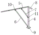
FIG. 1 is a schematic view of the overall structure of the present invention;
FIG. 2 is a schematic structural view of a ceiling form support unit according to the present invention;
FIG. 3 is a schematic view of a portion of the present invention;
FIG. 4 is a schematic diagram of a bevel support template according to the present invention.
In the figure: 1. a top plate formwork support unit; 2. a transverse pull rod; 3. combining the top plate templates; 4. supporting the upright post; 5. supporting the diagonal rods; 6. a middle pull rod; 7. an upper reinforcing tie rod; 8. supporting the ejector rod; 9. a bottom mounting plate; 10. connecting a hinged support; 11. the pull rod is provided with a sleeve; 12. the inclined plane supports the template; 13. the top supports the formwork.
Detailed Description
The technical solutions in the embodiments of the present invention will be clearly and completely described below with reference to the embodiments of the present invention, and it is obvious that the described embodiments are only a part of the embodiments of the present invention, rather than all embodiments, and all other embodiments obtained by a person of ordinary skill in the art without any creative work based on the embodiments of the present invention belong to the protection scope of the present invention.
While several embodiments of the present invention will be described more fully hereinafter with reference to the accompanying drawings, in order to facilitate an understanding of the utility model, the utility model may be embodied in many different forms and should not be construed as limited to the embodiments set forth herein, but rather should be construed to provide a more complete disclosure of the utility model.
It will be understood that when an element is referred to as being "secured to" another element, it can be directly on the other element or intervening elements may also be present, that when an element is referred to as being "connected" to another element, it can be directly connected to the other element or intervening elements may also be present, and that the terms "vertical", "horizontal", "left", "right" and the like are used herein for descriptive purposes only.
Unless defined otherwise, all technical and scientific terms used herein have the same meaning as commonly understood by one of ordinary skill in the art to which this invention belongs, and the terms used herein in the specification of the present invention are for the purpose of describing particular embodiments only and are not intended to limit the present invention, and the term "and/or" as used herein includes any and all combinations of one or more of the associated listed items.
Referring to fig. 1-4, the present invention provides a technical solution:
the utility model provides a built-up plate that oblique roofing of concrete was pour, includes roof template supporting unit 1, installs horizontal pull rod 2 between roof template supporting unit 1, and built-up roof template 3 is installed to the upside of roof template supporting unit 1.
Referring to fig. 1-4, a top plate formwork support unit 1 includes a support column 4, a support diagonal rod 5, a middle tie rod 6, an upper reinforcing tie rod 7 and a support post rod 8, a bottom mounting plate 9 is installed at the lower end of the support column 4, the support diagonal rod 5 is installed at the left side of the support column 4, the middle tie rod 6 is installed at the left upper side of the support column 4, the upper reinforcing tie rod 7 is installed at the left side of the support column 4 and located at the upper side of the middle tie rod 6, a connecting hinge base 10 is installed at the left side of the support column 4 and connected with the middle tie rod 6 and the upper reinforcing tie rod 7, tie rod mounting sleeves 11 are installed at the middle of the front and rear sides of the support column 4, the support post rod 8 is installed at the upper end of the support column 4, transverse tie rods 2 are symmetrically installed between the adjacent support diagonal rods 5 up and down, the tie rod mounting sleeves 11 are installed at the front and rear sides of the support diagonal rod 5 and at positions corresponding to the transverse tie rods 2, the bottom surface of the supporting diagonal rod 5 is provided with a connecting hinged support 10 at the joint with the middle pull rod 6 and the upper reinforcing pull rod 7, the middle pull rod 6 and the upper reinforcing pull rod 7 are provided with bolts at the joint with the connecting hinged support 10 at the two ends, the supporting upright post 4, the supporting diagonal rod 5, the middle pull rod 6, the upper reinforcing pull rod 7 and the supporting ejector rod 8 are all made of thin-wall steel pipes, the middle of the pull rod mounting sleeve 11 is provided with a bolt hole, the corners of the basal plane of the bottom mounting plate 9 are provided with mounting holes, the end part of the transverse pull rod 2 is matched with the pull rod mounting sleeve 11 in structure and size, the transverse pull rod 2 is connected with the pull rod mounting sleeve 11 through the bolts, the top plate template supporting units 1 are symmetrically provided with a plurality of groups left and right, the combined top plate template 3 comprises an inclined plane supporting template 12 and a top supporting template 13, the top supporting template 13 is transversely arranged at the upper end part of the inclined plane supporting template 12, the inclined plane supporting template 12 and the top supporting template 13 are both formed by combining a plurality of steel frame veneers, and the inclined plane supporting template 12 and the top supporting template 13 are installed by bolts, the top plate template supporting unit 1 is made of thin-wall steel pipes, so that the service life of the device is longer, the overall supporting stability and safety are stronger, meanwhile, the device adopts the mode of pin connection at a plurality of positions to ensure that the device is simple and convenient to assemble and disassemble, in addition, the combined top plate template 3 is made of steel frame plywood, so that the service life is longer, and the input amount of wood can be saved.
The working process of the utility model is as follows: during the use, roof template supporting unit 1 adopts the thin wall steel pipe preparation to form more and makes the life of this device longer on the one hand, and on the other hand makes holistic support stability and security stronger, and the mode that this device was gone on connecting in many places adoption pin makes the combination of this device and dismantles easy operation and convenience simultaneously, and built-up roof template 3 all chooses for use the steel frame plywood preparation to form in addition and makes its life longer, and can save ligneous input.
Although embodiments of the present invention have been shown and described, it will be appreciated by those skilled in the art that changes, modifications, substitutions and alterations can be made in these embodiments without departing from the principles and spirit of the utility model, the scope of which is defined in the appended claims and their equivalents.
Claims (8)
1. The utility model provides a built-up plate that oblique roofing of concrete was pour, includes roof template supporting element (1), its characterized in that: install horizontal pull rod (2) between roof template supporting unit (1), combination roof template (3) are installed to the upside of roof template supporting unit (1).
2. The composite formwork for pouring the concrete pitched roof according to claim 1, wherein: the top plate template supporting unit (1) comprises a supporting upright post (4), a supporting inclined rod (5), a middle pull rod (6), an upper side reinforcing pull rod (7) and a supporting ejector rod (8), a bottom mounting plate (9) is arranged at the lower end part of the supporting upright post (4), a supporting inclined rod (5) is arranged at the left side of the supporting upright post (4), a middle pull rod (6) is arranged at the left upper side of the supporting upright post (4), an upper reinforcing pull rod (7) is arranged at the left side of the supporting upright post (4) and positioned at the upper side of the middle pull rod (6), the left side of the supporting upright post (4) and the joints with the middle pull rod (6) and the upper side reinforcing pull rod (7) are both provided with a connecting hinged support (10), the middle parts of the front side and the rear side of the supporting upright post (4) are respectively provided with a pull rod mounting sleeve (11), and a support mandril (8) is arranged at the end part of the upper side of the support upright post (4).
3. The composite formwork for pouring the concrete pitched roof according to claim 2, wherein: it is adjacent support longitudinal symmetry between down tube (5) and install horizontal pull rod (2), support both sides around down tube (5) and install pull rod installation sleeve (11) with the position that horizontal pull rod (2) correspond, support the bottom surface of down tube (5) and all install connection free bearing (10) with the junction of middle part pull rod (6), upside reinforcing bar (7), the both ends of middle part pull rod (6), upside reinforcing bar (7) and install the bolt with the junction of connecting free bearing (10), support stand (4), support down tube (5), middle part pull rod (6), upside reinforcing bar (7) and support ejector pin (8) all select for use thin wall steel pipe preparation to form.
4. The composite formwork for pouring the concrete pitched roof according to claim 2, wherein: bolt holes are formed in the middle of the pull rod mounting sleeve (11), and mounting holes are formed in corners of a base surface of the bottom mounting plate (9).
5. The composite formwork for pouring the concrete pitched roof according to claim 1, wherein: the structure and the size of the end part of the transverse pull rod (2) are matched with the pull rod mounting sleeve (11), and the transverse pull rod (2) is connected with the pull rod mounting sleeve (11) through a bolt.
6. The composite formwork for pouring the concrete pitched roof according to claim 1, wherein: the top plate template supporting units (1) are symmetrically arranged at the left and right sides of the top plate template supporting unit.
7. The composite formwork for pouring the concrete pitched roof according to claim 1, wherein: the combined top plate template (3) comprises an inclined plane supporting template (12) and a top supporting template (13), and the top supporting template (13) is transversely installed at the end part of the upper side of the inclined plane supporting template (12).
8. The composite form for pouring of a concrete pitched roof according to claim 7, characterized in that: inclined plane support template (12) and top support template (13) all select a plurality of steel frame plywood combinations for use to form, and inclined plane support template (12) and top support template (13) are all installed through the bolt.
Priority Applications (1)
| Application Number | Priority Date | Filing Date | Title |
|---|---|---|---|
| CN202122042047.2U CN215564416U (en) | 2021-08-27 | 2021-08-27 | Combined template for pouring concrete inclined roof |
Applications Claiming Priority (1)
| Application Number | Priority Date | Filing Date | Title |
|---|---|---|---|
| CN202122042047.2U CN215564416U (en) | 2021-08-27 | 2021-08-27 | Combined template for pouring concrete inclined roof |
Publications (1)
| Publication Number | Publication Date |
|---|---|
| CN215564416U true CN215564416U (en) | 2022-01-18 |
Family
ID=79843206
Family Applications (1)
| Application Number | Title | Priority Date | Filing Date |
|---|---|---|---|
| CN202122042047.2U Active CN215564416U (en) | 2021-08-27 | 2021-08-27 | Combined template for pouring concrete inclined roof |
Country Status (1)
| Country | Link |
|---|---|
| CN (1) | CN215564416U (en) |
-
2021
- 2021-08-27 CN CN202122042047.2U patent/CN215564416U/en active Active
Similar Documents
| Publication | Publication Date | Title |
|---|---|---|
| CN205000554U (en) | A concrete column for assembling overall structure | |
| CN201474292U (en) | Midsize template assembled large template | |
| CN201535064U (en) | Template for buildings | |
| CN202064634U (en) | Formwork supporting structure for square concrete cap | |
| CN203201140U (en) | Beam slab support | |
| CN215564416U (en) | Combined template for pouring concrete inclined roof | |
| CN105332450B (en) | A kind of exterior wall disassembly-free thermal-insulation form board quickly assembled | |
| CN106351429A (en) | Heavy support system and construction method thereof | |
| CN207568164U (en) | A kind of socket joint type key slot type scaffold end branch stake tool | |
| CN213359377U (en) | Building templates support frame | |
| CN207727978U (en) | Girderless floor bolumn cap template reinforcing device | |
| CN206829610U (en) | A kind of removable variable cross-section steel framework wooden model | |
| CN109252879A (en) | A kind of vcehicular tunnel gutter liner tool-typed formwork and construction method | |
| CN215164433U (en) | Integral road surface basic unit resin template support frame | |
| CN201972395U (en) | Steel-frame double-layer-net building template | |
| CN2771386Y (en) | Foldable triangular frame for shuttering support column | |
| CN209163831U (en) | A kind of vcehicular tunnel gutter liner tool-typed formwork | |
| CN210263116U (en) | Rapid mounting and dismounting shaping template for concrete reverse filling of lower independent foundation | |
| CN210013503U (en) | Shear wall and column footing reinforcing device for solving concrete slab staggering between floors | |
| CN208650079U (en) | A kind of isolated footing cushion cap formwork ruggedized construction | |
| CN201620599U (en) | Rock wall crane beam concrete surface brace-free form of underground plant | |
| CN111535581A (en) | Convenient and fast mounting and dismounting type combined prefabricated formwork applicable to building floor lowering position | |
| CN106121219A (en) | A kind of huge post of stiffness is without screw aluminum alloy formwork system | |
| CN205894640U (en) | A safety protection and construction platform for construction of elevator well | |
| CN211974339U (en) | Windowsill template supporting device |
Legal Events
| Date | Code | Title | Description |
|---|---|---|---|
| GR01 | Patent grant | ||
| GR01 | Patent grant |