CN215546604U - Automatic water chamber assembling equipment for micro-channel heat exchanger core - Google Patents
Automatic water chamber assembling equipment for micro-channel heat exchanger core Download PDFInfo
- Publication number
- CN215546604U CN215546604U CN202121131456.3U CN202121131456U CN215546604U CN 215546604 U CN215546604 U CN 215546604U CN 202121131456 U CN202121131456 U CN 202121131456U CN 215546604 U CN215546604 U CN 215546604U
- Authority
- CN
- China
- Prior art keywords
- water chamber
- heat exchanger
- clamping
- clamping jaw
- exchanger core
- Prior art date
- Legal status (The legal status is an assumption and is not a legal conclusion. Google has not performed a legal analysis and makes no representation as to the accuracy of the status listed.)
- Active
Links
Images


Abstract
An automatic water chamber assembling device for a micro-channel heat exchanger core comprises an assembling table for placing the heat exchanger core, a clamping and conveying mechanism, a leveling mechanism and a water chamber assembling mechanism; the assembly table is provided with a core body assembly area and a water chamber assembly area, the clamping and conveying mechanism is arranged beside the assembly table, the leveling mechanism is arranged above the water chamber assembly area, and the water chamber assembly mechanisms are respectively arranged at two sides of the water chamber assembly area; after the clamping and conveying mechanism can clamp the heat exchanger core and move to the water chamber assembly area, the flattening mechanism acts to press the heat exchanger core, and the water chamber assembly mechanisms on the two sides respectively assemble the water chambers to the heat exchanger core. The utility model adopts the clamping and conveying mechanism, the leveling mechanism and the water chamber assembly mechanism, so that the automatic conveying of the core body and the automatic assembly of the water chamber can be realized, the labor intensity of operators is reduced, and the production efficiency is also improved.
Description
Technical Field
The utility model relates to automatic assembling equipment for a heat exchanger core, in particular to automatic assembling equipment for a water chamber of a micro-channel heat exchanger core.
Background
The micro-channel heat exchanger core generally comprises flat pipes, fins, a main plate and side plates, and is assembled through a core assembling machine, but the micro-channel heat exchanger core is a semi-finished core, and is manually taken down from a workbench of the assembling machine, carried to a water chamber assembling area, and then a water chamber is manually installed on the semi-finished core, so that the micro-channel heat exchanger core is assembled. Like this through the manual work core of taking off and equipment hydroecium, operating personnel's intensity of labour is great, and production efficiency is low moreover, also does not benefit to the automatic line of core production.
Disclosure of Invention
The technical problem to be solved by the utility model is to overcome the defects in the prior art and provide automatic water chamber assembling equipment for a core body of a micro-channel heat exchanger, which can automatically complete semi-finished core body conveying and water chamber installation, is favorable for reducing the labor intensity of operators and improves the production efficiency of the core body.
The technical scheme adopted by the utility model for solving the technical problems is as follows:
an automatic water chamber assembling device for a micro-channel heat exchanger core comprises an assembling table for placing the heat exchanger core, a clamping and conveying mechanism, a leveling mechanism and a water chamber assembling mechanism; the assembly table is provided with a core body assembly area and a water chamber assembly area, the clamping and conveying mechanism is arranged beside the assembly table, the leveling mechanism is arranged above the water chamber assembly area, and the water chamber assembly mechanisms are respectively arranged at two sides of the water chamber assembly area; after the clamping and conveying mechanism can clamp the heat exchanger core and move to the water chamber assembly area, the flattening mechanism acts to press the heat exchanger core, and the water chamber assembly mechanisms on the two sides respectively assemble the water chambers to the heat exchanger core.
Preferably, the assembly table, the clamping and conveying mechanism, the leveling mechanism and the water chamber assembly mechanism are all arranged on the rack.
More specifically, the clamping and conveying mechanism comprises a moving mechanism and a clamping mechanism, wherein the moving mechanism is connected with the clamping mechanism and moves the clamping mechanism, and the clamping mechanism can clamp or release the heat exchanger core.
More specifically, moving mechanism includes actuating mechanism, drive mechanism, and is more specifically, actuating mechanism is mobile motor, and drive mechanism is including installation crossbeam, lead screw, screw-nut, slip table, mobile motor installs on the installation crossbeam, and its output shaft is connected with the lead screw, the lead screw both ends are respectively through installation crossbeam roll support, screw-nut wears the cover on the lead screw to install on the slip table, fixture is the clamping jaw, the clamping jaw sets up on the slip table. The clamping jaw clamps tight semi-manufactured goods core, then drives the lead screw through the removal motor and rotates, drives the slip table and the clamping jaw on it through screw-nut and removes, makes the clamping jaw drive semi-manufactured goods core and remove to hydroecium equipment district.
Preferably, a sliding table guide mechanism is arranged between the sliding table and the mounting cross beam, more particularly, the sliding table guide mechanism is a sliding block sliding rail guide mechanism, the sliding block is mounted on the sliding table, and the sliding rail is mounted on the mounting cross beam, so that the sliding table can move stably along the sliding rail, and the clamping jaw can move stably.
For better clamping of the heat exchanger core, the clamping jaws comprise a fixed clamping jaw as a reference for clamping the core and a moving clamping jaw which is connected to the clamping jaw moving mechanism and is movable relative to the fixed clamping jaw under the drive of the clamping jaw moving mechanism, whereby the degree of clamping of the heat exchanger core is controlled by the clamping force imparted by the moving mechanism to the moving clamping jaw.
More specifically, fixed clamping jaw is installed on the mounting panel, the mounting panel is installed on the slip table, moving mechanism includes the electric jar, the electric jar is installed on the mounting panel, remove the clamping jaw and install on the movable plate of electric jar, the movable plate moves through the flexible of electric jar piston rod to the distance between change removal clamping jaw and the fixed clamping jaw presss from both sides tightly or unclamps the core. And the electric cylinder is adopted to control the movable clamping jaw to clamp the heat exchanger core, so that the clamping consistency is good, the size change degree of the core is small, and the influence on the core in the conveying process is avoided.
In order to take off the core or carry other positions with the core from the hydroecium equipment district, need the clamping jaw to move the position that is less than the installation crossbeam, avoid taking place to interfere, still set up clamping jaw elevating system, clamping jaw elevating system drive clamping jaw goes up and down.
More specifically, clamping jaw elevating system includes lift cylinder and cylinder mounting panel, the lift cylinder is four, installs the four corners at the cylinder mounting panel respectively, the piston rod of four cylinders all is connected with the mounting panel, the cylinder mounting panel is installed on the slip table, and like this, clamping jaw elevating system drives the mounting panel and the clamping jaw on it goes up and down through cylinder piston rod's flexible.
Preferably, in order to make the clamping jaw rise and fall steadily, clamping jaw guiding mechanism has still been set up, more specifically, clamping jaw guiding mechanism includes guide bar and linear bearing, the guide bar upper end is fixed on the mounting panel, linear bearing wears to overlap outside the guide bar to install on the cylinder mounting panel. Thus, the clamping jaw guide mechanism can guide the guide rod to stably lift through the linear bearing.
Preferably, the flat beating mechanism comprises a flat beating plate, a horizontal moving mechanism and an up-down moving mechanism; the horizontal moving mechanism comprises an air cylinder and a moving frame, the air cylinder is installed on the rack, the moving frame is connected with a sliding table of the air cylinder, and the sliding table drives the moving frame to horizontally move in a reciprocating mode under the action of the air cylinder.
In order to enable the translation frame to move stably, a translation frame guide mechanism is arranged between the translation frame and the rack, and more specifically, the translation frame guide mechanism is a slide block and slide rail guide mechanism, the slide block is installed on the translation frame, and the slide rail is installed on the rack.
The up-down moving mechanism comprises an upper air cylinder, a lower air cylinder and a transition plate, the upper air cylinder and the lower air cylinder are arranged on the translation frame, piston rods of the upper air cylinder and the lower air cylinder are connected with the transition plate, and the transition plate is driven to move up and down through the extension and contraction of the piston rods of the upper air cylinder and the lower air cylinder.
In order to enable the transition plate to stably move up and down, a transition plate guide mechanism is further arranged and comprises a guide rod and a linear bearing, the upper end of the guide rod is fixed on the limiting plate, the lower end of the guide rod is fixed on the transition plate, and the linear bearing is sleeved outside the guide rod and is arranged on the translation frame.
The clapper plate is arranged on the transition plate, so that the clapper plate can move up and down and horizontally under the action of the horizontal mechanism and the up-down mechanism.
Preferably, the clapper plate is movably mounted on the transition plate, the clapper plate is connected with two T-shaped blocks, the T-shaped blocks are inserted into T-shaped grooves of the mounting blocks, the mounting blocks are mounted on the transition plate, one end of each mounting block is provided with a limiting block mounted on the transition plate, the other end of each mounting block is provided with a pressing plate, one end of each pressing plate is rotatably connected to the transition plate and more particularly hung on a screw through screwing the screw into the transition plate, the other end of each pressing plate is in threaded connection with the handle, the inner end of the handle penetrates through the pressing plate and is aligned with the end face of the T-shaped block, and therefore the handle can be continuously rotated, the end of each pressing plate abuts against the end face of one end of the T-shaped block, the T-shaped block is pushed to move until the end face of the other end of the T-shaped block is abutted against by the limiting block, and the clapper plate is fixed. When the core specification changes, the screw thread handle is rotated to make it leave the terminal surface of T type piece to rotatory briquetting gives the T type piece and lets out the position, just so can change the bat flat board fast, laborsavingly.
More specifically, hydroecium equipment mechanism is including assembling the motor, lifting machine, nut, lifting machine mount pad, die holding seat, hydroecium mould, the motor is installed on the mount pad, and it is connected and drive with the machine of lifting, the machine of lifting is also supported by the machine mount pad of lifting, the nut wears to overlap outside the lead screw of the machine of lifting to install on the die holding seat, hydroecium die holding is at the tip of die holding seat, the machine mount pad of lifting is installed in the frame, the hydroecium is installed on the hydroecium mould. Therefore, the motor of the water chamber assembling mechanism drives the lifting machine, so that the screw rod of the lifting machine drives the nut and the water chamber connected with the nut to move, and the water chamber is installed at two ends of the core body.
In order to enable the die mounting seat to stably move, a die mounting seat guide mechanism is further arranged, specifically, the die mounting seat guide mechanism is a slide block and slide rail guide mechanism, a slide block is arranged on the die mounting seat, and a slide rail is arranged on the rack.
Compared with the prior art, the utility model has the advantages that: the clamping and conveying mechanism, the leveling mechanism and the water chamber assembling mechanism are adopted, so that automatic core conveying and automatic water chamber assembling can be realized, the labor intensity of operators is reduced, and the production efficiency is improved.
Drawings
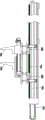
Fig. 1 is a schematic three-dimensional structure diagram of an automatic assembly device for a water chamber of a core body of a microchannel heat exchanger according to an embodiment of the present invention.
Fig. 2 is a three-dimensional schematic view of a clamping and conveying mechanism of automatic water chamber assembling equipment for a core body of a micro-channel heat exchanger.
FIG. 3 is a side view of the pinch mechanism of FIG. 2.
Fig. 4 is a three-dimensional schematic view of a leveling mechanism of an automatic water chamber assembly device for a core body of a microchannel heat exchanger according to an embodiment of the present invention.
Fig. 5 is a three-dimensional schematic view illustrating a connection between a leveling plate and a transition plate of an automatic assembly device for a water chamber of a core of a microchannel heat exchanger according to an embodiment of the present invention.
Fig. 6 is a side view of fig. 5.
Fig. 7 is a three-dimensional schematic view of a water chamber assembly mechanism of an automatic water chamber assembly device for a core body of a microchannel heat exchanger according to an embodiment of the present invention.
Detailed Description
The utility model is described in further detail below with reference to the accompanying examples.
As shown in fig. 1, an automatic assembling device for a water chamber of a core of a micro-channel heat exchanger includes a frame 1, an assembling table 2, a clamping and conveying mechanism 3, a leveling mechanism 4, and water chamber assembling mechanisms 5 and 6.
The assembly table 2 is installed on the rack 1, and a core body assembly area and a water chamber assembly area are arranged on the assembly table.
The clamping and conveying mechanism 3 is arranged on the rack 1 and beside the assembling table 2, and comprises a motor 301, an installation beam 302, a screw rod 303, a screw rod nut, a sliding table 304 and clamping jaws 305 and 305'.
The motor 301 is installed on the installation beam 302, an output shaft of the motor is connected with the screw rod 303, two ends of the screw rod 303 are respectively supported by the installation beam 302 in a rolling manner, the screw rod nut (not shown in the figure) is sleeved on the screw rod 303 and installed on the sliding table 304, and the clamping jaws 305 and 305' are arranged on the sliding table 304.
The clamping jaws 305 and 305 ' are used for clamping the semi-finished core 8, then the motor 301 drives the screw rod 303 to rotate, the screw rod nut drives the sliding table 304 and the clamping jaws 305 and 305 ' thereon to move, so that the clamping jaws 305 and 305 ' drive the semi-finished core 8 to move to the water chamber assembly area along the arrow direction in fig. 1.
In order to make the clamping jaws 305 and 305' move smoothly with the core 8, a slide rail guide mechanism is provided between the slide table 304 and the mounting cross beam 302, the slide block 306 is mounted on the slide table 304, and the slide rail 307 is mounted on the mounting cross beam 302, so that the slide table moves smoothly along the slide rail 307.
For better clamping of the core 8, the clamping jaws 305 are fixed and, as a reference for clamping the core 8, the clamping jaws 305 'are movable, the degree of clamping of the core 8 being controlled by the clamping force imparted to the clamping jaws 305' by the moving mechanism.
The clamping jaw 305 is mounted on a mounting plate 308, the moving mechanism comprises an electric cylinder 309, the electric cylinder 309 is mounted on the mounting plate 308, and the clamping jaw 305' is mounted on a moving plate 310 of the electric cylinder 309. The movable plate 310 is driven to move by the extension and contraction of the piston rod of the electric cylinder 309, so that the clamping jaw 305' is driven to relatively fix the distance between the clamping jaws 305, and the core body is clamped or loosened.
The mounting plate 308 may be mounted directly on the slide table 304, but in order to remove the core from the water chamber assembly area or transport the core to another location, the clamping jaws 305 and 305' need to be moved to a position lower than the mounting cross member 302 to avoid interference, so a clamping jaw lifting mechanism is also provided.
Clamping jaw elevating system includes cylinder 311 and cylinder mounting panel 312, the cylinder is four, installs the four corners at cylinder mounting panel 312 respectively, four cylinders 311 all are connected with mounting panel 308, cylinder mounting panel 312 is installed on slip table 304. The piston rod of the air cylinder 311 extends and retracts to drive the mounting plate 308 and the clamping jaws 305 and 305' on the mounting plate to lift.
In order to make the clamping jaws 305 and 305' rise and fall smoothly, a guide mechanism is further provided, the guide mechanism comprises a guide rod 313 and a linear bearing 314, the upper end of the guide rod 313 is fixed on the mounting plate 308, and the linear bearing 314 is sleeved outside the guide rod 313 and is mounted on the cylinder mounting plate 312.
As shown in fig. 4, the flap mechanism 4 is disposed above the water chamber assembly area of the assembly table 2, and includes a flap plate 401, a horizontal movement mechanism, and an up-down movement mechanism.
The horizontal moving mechanism comprises an air cylinder 402 and a translation frame 403, the air cylinder 402 is installed on the rack 1, the translation frame 403 is connected with a sliding table 4021 of the air cylinder 402, and the sliding table 4021 drives the translation frame 403 to horizontally reciprocate under the action of the air cylinder 402.
In order to make the translation frame move smoothly, a slide block and slide rail guide mechanism is arranged between the translation frame 403 and the machine frame 1, the slide block 404 is installed on the translation frame 403, and the slide rail 405 is installed on the machine frame 1.
The up-down moving mechanism comprises an air cylinder 406 and a transition plate 407, the air cylinder 406 is mounted on the translation frame 403, a piston rod of the air cylinder is connected with the transition plate 407, and the transition plate 407 is driven to move up and down by the extension and contraction of the air cylinder piston rod.
In order to enable the transition plate 407 to move up and down stably, a guide mechanism is further arranged, the guide mechanism comprises a guide rod 408 and a linear bearing 409, the upper end of the guide rod 408 is fixed on the limiting plate 410, the lower end of the guide rod 408 is fixed on the transition plate 407, and the linear bearing 409 is sleeved outside the guide rod 408 and is installed on the translation frame 403.
The clapper board 401 is arranged on the transition board 407, so that the clapper board 401 can move up and down and horizontally under the action of the horizontal mechanism and the up-down mechanism.
The clapper board 401 can be directly mounted on the transition plate 407 through a screw, or movably mounted on the transition plate 407, as shown in fig. 5 and 6, the clapper board 401 is connected with two T-shaped blocks 411, the T-shaped blocks 411 are inserted into T-shaped grooves 4121 of the mounting block 412, the mounting block 412 is mounted on the transition plate 407, one end of the mounting block is provided with a limit block 413 mounted on the transition plate 407, the other end of the mounting block is provided with a pressing plate 414, one end of the pressing plate 414 is screwed into the transition plate 407 through the screw 415 and hung on the screw 415, the other end of the pressing plate is screwed with a threaded handle 416, the threaded handle 416 is continuously rotated to enable the end to abut against the end face of one end of the T-shaped block 411, the T-shaped block 411 is pushed to move, the end face of the other end of the T-shaped block abuts against the limit block 413, and thus the clapper board 401 is fixed. When the core specification changes, the threaded handle 416 is rotated to be away from the end face of the T-shaped block 411, and the pressing block 414 is rotated to give way to the T-shaped block, so that the clapper plate 401 can be replaced quickly, and time and labor are saved.
As shown in fig. 7, the water chamber assembling mechanism 5 and the water chamber assembling mechanism 6 are the same water chamber assembling mechanism, are symmetrically disposed on both sides of the water chamber assembling area of the assembling table 2, and respectively include a motor 501, a lifter 502, a nut 503, a lifter mount 504, a mold mount 505, and a water chamber mold 506. The water chamber mold 506 is aligned with the mounting end of the core 8 as the core 8 is transported to the water chamber assembly area.
The motor 501 is mounted on a mounting base 504, is connected with the lifter 502 and drives the lifter 502,
the lifting machine 502 is also supported by the lifting machine mounting seat 504, the nut 503 is sleeved outside the screw rod 5021 of the lifting machine 502 and is mounted on the die mounting seat 505, the water chamber die 506 is mounted at the end of the die mounting seat 505, the lifting machine mounting seat 504 is mounted on the frame 1, and the water chamber is mounted on the water chamber die 506. The motors 501 of the water chamber assembling mechanisms 5 and 6 drive the lifting machine 502 to make the screw rod 5021 drive the nut 503 and the water chamber connected with the nut to move, and the water chambers are installed at two ends of the core body 8.
In order to make the mold mounting seat 505 move smoothly, a slide rail guide mechanism is further provided, the slide 507 is mounted on the mold mounting seat 505, and the slide rail 508 is mounted on the machine frame 1.
The core body assembly water chamber process is as follows.
1. After the main plate of the core 8 is assembled in the main plate assembly area, as shown in fig. 1, the piston rod of the cylinder 311 extends to lift the clamping jaws 305 and 305 'to a certain position to stop, and then the electric cylinder 309 drives the clamping jaw 305' to move to clamp the core 8.
2. Motor 301 is activated to move jaws 305 and 305' to grip core 8 in the direction indicated by the arrows to the water chamber assembly area.
3. When the water chamber assembly area is reached, the clamping jaws 305 and 305' continue to maintain the clamped state, the clapper mechanism 4 moves the clapper plate 401 horizontally to reach above the core body 8, and then the piston rod of the air cylinder 406 extends to lower the clapper plate 401 and press the core body 8 from above.
4. The two motors 501 are activated to make the mold mount 505 drive the water chamber mold 506 and the water chamber mounted thereon to move toward the core, and the assembly is completed.
5. When the water chamber is automatically assembled, the water chamber mold 506 retracts, the clapper plate 401 rises and retracts horizontally, the electric cylinder 309 drives the clamping jaws 305 ' to move, the core body 8 is loosened, the piston rod of the air cylinder 311 retracts, the clamping jaws 305 and 305 ' are driven to descend, and the motor 301 is started to drive the clamping jaws 305 and 305 ' to retract along the opposite directions of arrows.
6. And repeating the steps 1-4 to finish the conveying of the next core body and the automatic installation of the water chamber.
Claims (10)
1. The utility model provides an automatic equipment of hydroecium of microchannel heat exchanger core, characterized by: the device comprises an assembly table for placing a heat exchanger core, a clamping and conveying mechanism, a leveling mechanism and a water chamber assembly mechanism; the assembly table is provided with a core body assembly area and a water chamber assembly area, the clamping and conveying mechanism is arranged beside the assembly table, the leveling mechanism is arranged above the water chamber assembly area, and the water chamber assembly mechanisms are respectively arranged at two sides of the water chamber assembly area; after the clamping and conveying mechanism can clamp the heat exchanger core and move to the water chamber assembly area, the flattening mechanism acts to press the heat exchanger core, and the water chamber assembly mechanisms on the two sides respectively assemble the water chambers to the heat exchanger core.
2. The automated microchannel heat exchanger core water chamber assembly apparatus of claim 1, wherein: the assembly table, the clamping and conveying mechanism, the leveling mechanism and the water chamber assembly mechanism are all installed on the rack.
3. The automated microchannel heat exchanger core water chamber assembly apparatus of claim 1, wherein: the clamping and conveying mechanism comprises a moving mechanism and a clamping mechanism, the moving mechanism is connected with the clamping mechanism and moves the clamping mechanism, and the clamping mechanism can clamp or release the heat exchanger core.
4. The automated microchannel heat exchanger core water chamber assembly apparatus of claim 3, wherein: the moving mechanism comprises a driving mechanism and a transmission mechanism, the driving mechanism is a moving motor, the transmission mechanism comprises an installation cross beam, a screw rod, a screw nut and a sliding table, the moving motor is installed on the installation cross beam, an output shaft of the moving motor is connected with the screw rod, two ends of the screw rod are respectively supported by the installation cross beam in a rolling manner, the screw nut is sleeved on the screw rod in a penetrating manner and is installed on the sliding table, the clamping mechanism is a clamping jaw, and the clamping jaw is arranged on the sliding table; a sliding table guide mechanism is arranged between the sliding table and the mounting cross beam, the sliding table guide mechanism is a sliding block sliding rail guide mechanism, the sliding block is mounted on the sliding table, and the sliding rail is mounted on the mounting cross beam.
5. The automated microchannel heat exchanger core water chamber assembly apparatus of claim 4, wherein: the clamping jaw includes fixed clamping jaw and removal clamping jaw, it links to each other and can move relatively fixed clamping jaw under the moving mechanism drive to remove clamping jaw and clamping jaw moving mechanism, fixed clamping jaw installs on the mounting panel, the mounting panel is installed on the slip table, clamping jaw moving mechanism includes the electric jar, the electric jar is installed on the mounting panel, remove the clamping jaw and install on the movable plate of electric jar, the movable plate moves through the flexible of electric jar piston rod to change the distance between removal clamping jaw and the fixed clamping jaw and press from both sides tightly or loosen the core.
6. The automated microchannel heat exchanger core water chamber assembly apparatus of claim 4, wherein: the clamping jaw lifting mechanism is arranged and drives the clamping jaw to lift, the clamping jaw lifting mechanism comprises four lifting cylinders and cylinder mounting plates, the four lifting cylinders are respectively mounted at four corners of the cylinder mounting plates, piston rods of the four cylinders are connected with the mounting plates, and the cylinder mounting plates are mounted on the sliding table; still set up clamping jaw guiding mechanism, clamping jaw guiding mechanism includes guide bar and linear bearing, the guide bar upper end is fixed on the mounting panel, linear bearing wears to overlap outside the guide bar to install on the cylinder mounting panel.
7. The automatic assembly apparatus of the water chamber of the micro-channel heat exchanger core according to claim 1 or 2, wherein: the flat beating mechanism comprises a flat beating plate, a horizontal moving mechanism and an up-down moving mechanism; the horizontal moving mechanism comprises an air cylinder and a translation frame, the air cylinder is arranged on the rack, the translation frame is connected with a sliding table of the air cylinder, and the sliding table drives the translation frame to horizontally reciprocate under the action of the air cylinder; the sliding frame guide mechanism is arranged between the sliding frame and the rack, the sliding frame guide mechanism is a sliding block sliding rail guide mechanism, the sliding block is installed on the sliding frame, and the sliding rail is installed on the rack.
8. The automated microchannel heat exchanger core water chamber assembly apparatus of claim 7, wherein: the up-down moving mechanism comprises an upper air cylinder, a lower air cylinder and a transition plate, the upper air cylinder and the lower air cylinder are arranged on the translation frame, piston rods of the upper air cylinder and the lower air cylinder are connected with the transition plate, the transition plate is driven to move up and down through the extension and contraction of the piston rods of the upper air cylinder and the lower air cylinder, and the clapper plate is arranged on the transition plate; still set up and cross cab apron guiding mechanism, it includes guide bar and linear bearing to cross cab apron guiding mechanism, the guide bar upper end is fixed on the limiting plate, and the lower extreme is fixed on crossing the cab apron, linear bearing wears to overlap outside the guide bar to install on the translation frame.
9. The automated microchannel heat exchanger core water chamber assembly apparatus of claim 8, wherein: the bat dull and stereotyped movably installs on crossing the cab apron, it is connected with two T type pieces to clap the dull and stereotyped, T type piece inserts the T type inslot of installation piece, the installation piece is installed on crossing the cab apron, and its one end sets up the stopper of installing on crossing the cab apron, and the other end sets up the clamp plate, the one end of clamp plate is rotatably connected on crossing the cab apron, the other end and the handle threaded connection of clamp plate make the handle inner pass the clamp plate and aim at the terminal surface of T type piece.
10. The automatic assembly apparatus of the water chamber of the micro-channel heat exchanger core according to claim 1 or 2, wherein: the water chamber assembling mechanism comprises an assembling motor, a lifting machine, a nut, a lifting machine mounting seat, a mold mounting seat and a water chamber mold, wherein the motor is mounted on the mounting seat and connected with and driven by the lifting machine, the lifting machine is also supported by the lifting machine mounting seat, the nut is sleeved outside a screw rod of the lifting machine in a penetrating manner and is mounted on the mold mounting seat, the water chamber mold is mounted at the end part of the mold mounting seat, the lifting machine mounting seat is mounted on the rack, and the water chamber is mounted on the water chamber mold; the die mounting seat guide mechanism is a slide block and slide rail guide mechanism, the slide block is mounted on the die mounting seat, and the slide rail is mounted on the machine frame.
Priority Applications (1)
| Application Number | Priority Date | Filing Date | Title |
|---|---|---|---|
| CN202121131456.3U CN215546604U (en) | 2021-05-25 | 2021-05-25 | Automatic water chamber assembling equipment for micro-channel heat exchanger core |
Applications Claiming Priority (1)
| Application Number | Priority Date | Filing Date | Title |
|---|---|---|---|
| CN202121131456.3U CN215546604U (en) | 2021-05-25 | 2021-05-25 | Automatic water chamber assembling equipment for micro-channel heat exchanger core |
Publications (1)
| Publication Number | Publication Date |
|---|---|
| CN215546604U true CN215546604U (en) | 2022-01-18 |
Family
ID=79863585
Family Applications (1)
| Application Number | Title | Priority Date | Filing Date |
|---|---|---|---|
| CN202121131456.3U Active CN215546604U (en) | 2021-05-25 | 2021-05-25 | Automatic water chamber assembling equipment for micro-channel heat exchanger core |
Country Status (1)
| Country | Link |
|---|---|
| CN (1) | CN215546604U (en) |
Cited By (1)
| Publication number | Priority date | Publication date | Assignee | Title |
|---|---|---|---|---|
| CN116214152A (en) * | 2022-12-30 | 2023-06-06 | 绍兴百立杰环保科技有限公司 | Assembling device for total heat exchange core |
-
2021
- 2021-05-25 CN CN202121131456.3U patent/CN215546604U/en active Active
Cited By (2)
| Publication number | Priority date | Publication date | Assignee | Title |
|---|---|---|---|---|
| CN116214152A (en) * | 2022-12-30 | 2023-06-06 | 绍兴百立杰环保科技有限公司 | Assembling device for total heat exchange core |
| CN116214152B (en) * | 2022-12-30 | 2023-11-07 | 绍兴百立杰环保科技有限公司 | Assembling device for total heat exchange core |
Similar Documents
| Publication | Publication Date | Title |
|---|---|---|
| CN109773267B (en) | Long round bar cutting machine | |
| CN104918476A (en) | Power amplifier assembly | |
| CN215546604U (en) | Automatic water chamber assembling equipment for micro-channel heat exchanger core | |
| CN107671199A (en) | Bender | |
| CN219378605U (en) | Punching machine | |
| CN109823827B (en) | Winding wire feeding and discharging device | |
| CN116689988A (en) | Full-automatic cutting device for carriage plates | |
| CN113953551B (en) | Full-automatic drilling machine | |
| CN214212698U (en) | Welding positioning platform | |
| CN214518971U (en) | Machine external clamp anchor clamps | |
| CN112959105A (en) | Numerical control machining clamp for thin plate | |
| CN213915595U (en) | Automatic bending device | |
| CN211028870U (en) | Hydraulic cylinder mounting device | |
| CN211330854U (en) | Double-arm stretch bender stretching seat moving mechanism | |
| CN208932625U (en) | A kind of film molding automatic feeding | |
| CN209871695U (en) | Winding loading and unloading device | |
| CN220612775U (en) | Sheet metal part forming and welding device | |
| CN109420900B (en) | Automobile gear shifter core rod mounting device | |
| CN219443033U (en) | Ribbon presser foot machine | |
| CN217344218U (en) | Auxiliary frame assembling equipment | |
| CN220720402U (en) | Single-arm press convenient for loading and unloading | |
| CN219541419U (en) | Segmented bending mechanism of numerical control bending machine | |
| CN219906732U (en) | Lifting mechanism for bus duct production | |
| CN216421676U (en) | Multidirectional two workstations of adjusting | |
| CN219767419U (en) | Numerical control tooth flattening machine |
Legal Events
| Date | Code | Title | Description |
|---|---|---|---|
| GR01 | Patent grant | ||
| GR01 | Patent grant |