CN215544149U - Downpipe clip punching device - Google Patents
Downpipe clip punching device Download PDFInfo
- Publication number
- CN215544149U CN215544149U CN202122190071.0U CN202122190071U CN215544149U CN 215544149 U CN215544149 U CN 215544149U CN 202122190071 U CN202122190071 U CN 202122190071U CN 215544149 U CN215544149 U CN 215544149U
- Authority
- CN
- China
- Prior art keywords
- punch
- positioning
- base
- punching
- handle
- Prior art date
- Legal status (The legal status is an assumption and is not a legal conclusion. Google has not performed a legal analysis and makes no representation as to the accuracy of the status listed.)
- Active
Links
Images


Landscapes
- Perforating, Stamping-Out Or Severing By Means Other Than Cutting (AREA)
Abstract
The utility model discloses a downpipe clip punching device which comprises a base; the table top of the base is provided with a left group of upright posts and a right group of upright posts and is also provided with a positioning body positioned on the front sides of the upright posts; a positioning groove for placing a workpiece is arranged between the positioning body and the table surface of the base; the positioning body is provided with a left group of guide holes and a right group of guide holes which are vertically communicated with the positioning groove, a punch is respectively arranged in each guide hole, and a reset spring for similarly pushing the punch is also arranged between the arc punch handle at the upper end of the punch and the top of the positioning body; a blanking hole corresponding to the punch is formed on the table top of the base; the punching device also comprises a door-shaped pressing handle, and two support legs at the lower end of the pressing handle are respectively and rotatably connected with the two stand columns; the pressing handle is used for pressing the punching handle of the punching head. The utility model realizes the mechanized punching of the downpipe clip, can synchronously complete the processing of two holes through the positioning groove and the two groups of punches, and has high efficiency and high tapping quality.
Description
Technical Field
The utility model relates to a device for punching a downpipe clip.
Background
The downpipe clip is usually made of 0.5mm color steel plates, and two ends of the downpipe clip are provided with small holes of 6 mm.
In the traditional manufacturing process, the small holes at the two ends are manually marked and punched by using a sample, and one clamp needs to be punched twice to complete processing. The method has low efficiency and needs two working procedures of marking and punching twice. And the punching precision of manual sample punching is low, and the product quality can not be ensured.
SUMMERY OF THE UTILITY MODEL
The utility model provides a downpipe clip punching device, which aims to: the punching efficiency is improved, and the size is guaranteed to be accurate.
The technical scheme of the utility model is as follows:
a downpipe clip punching device comprises a base; the table top of the base is provided with a left group of upright posts and a right group of upright posts and a positioning body positioned on the front sides of the upright posts;
a positioning groove for placing a workpiece is arranged between the positioning body and the table surface of the base; the positioning body is provided with a left group of guide holes and a right group of guide holes which are vertically communicated with the positioning grooves, a punch is respectively arranged in each guide hole, and a reset spring for similarly pushing the punch is also arranged between the arc punch handle at the upper end of the punch and the top of the positioning body;
a blanking hole corresponding to the punch is formed in the table top of the base;
the punching device also comprises a door-shaped pressing handle, and two support legs at the lower end of the pressing handle are respectively and rotatably connected with the two stand columns; the pressing handle is used for pressing the punching handle of the punching head.
As a further improvement of the device: the positioning body comprises an upper positioning block, a lower positioning block and a left positioning sleeve and a right positioning sleeve; the upper positioning block and the lower positioning block respectively comprise a left vertical through hole and a right vertical through hole; step shafts at the upper end and the lower end of the positioning sleeve are respectively inserted into through holes at the corresponding sides of the upper positioning block and the lower positioning block; the inner hole of the positioning sleeve is the guide hole.
As a further improvement of the device: the positioning groove is formed in the bottom surface of the lower positioning block.
As a further improvement of the device: the front side of the table-board of the base is provided with a first notch, the front side of the lower positioning block is provided with a second notch corresponding to the first notch in position, and the first notch and the second notch form a feeding port.
As a further improvement of the device: and the pressing handle is provided with a bulge corresponding to the punching handle of the punching head.
As a further improvement of the device: the lower end of the punch is of a step type.
As a further improvement of the device: the base also includes legs for supporting the table top.
Compared with the prior art, the utility model has the following beneficial effects: (1) the device realizes mechanical punching, can synchronously finish the processing of two holes through the positioning groove and the two groups of punches, and has high efficiency and high tapping quality; (2) the automatic resetting of the punch can be realized through the reset spring; (3) waste can be automatically discharged through the blanking hole; (4) the workpiece can be conveniently taken and placed through the feeding port, so that the operation efficiency is further improved; (5) the lower end of the punch is in a step shape, so that the strength can be improved.
Drawings
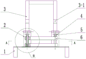
FIG. 1 is a schematic view of the overall structure of the apparatus;
FIG. 2 is a view A-A of FIG. 1;
FIG. 3 is an enlarged view of a portion B of FIG. 1;
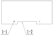
FIG. 4 is a top view of the base;
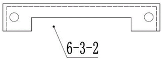
FIG. 5 is a top view of the lower locating block;
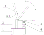
fig. 6 is a schematic view of punching using the apparatus.
Detailed Description
The technical scheme of the utility model is explained in detail in the following with the accompanying drawings:
referring to fig. 1 and 6, the downpipe clip punching device comprises a base 1, wherein the base 1 comprises a horizontal table top and four legs for supporting the table top.
As shown in fig. 1, 2 and 6, two sets of left and right upright posts 2 and a positioning body 6 positioned at the front side of the upright posts 2 are welded on the table top of the base 1.
As shown in fig. 3, a positioning groove 6-3-1 for placing the sheet-shaped workpiece is arranged between the positioning body 6 and the table-board of the base 1. The positioning body 6 is provided with a left group of guide holes and a right group of guide holes which are vertically communicated with the positioning groove 6-3-1, a punch 4 is respectively arranged in each guide hole, and a reset spring 5 for similarly pushing the punch 4 is also arranged between an arc punch handle used for bearing force at the upper end of the punch 4 and the top of the positioning body 6. Preferably, a gasket is further arranged on the upper end face of the guide hole of the positioning body 6, and the lower end face of the return spring 5 is pressed on the gasket.
Specifically, as shown in fig. 3, the positioning body 6 includes an upper positioning block 6-1, a lower positioning block 6-3, and two left and right sets of positioning sleeves 6-2. The upper positioning block 6-1 and the lower positioning block 6-3 respectively comprise a left vertical through hole and a right vertical through hole; the middle of the positioning sleeve 6-2 is provided with an upper group of shoulder surfaces and a lower group of shoulder surfaces, and step shafts with thin upper ends and thin lower ends are respectively inserted into through holes on the corresponding sides of the upper positioning block 6-1 and the lower positioning block 6-3 and are in transition fit, and the upper positioning block, the lower positioning block, the upper positioning block and the lower positioning block are fixed into a whole. The lower positioning blocks 6-3 are welded on the table-board of the base 1. The inner hole of the positioning sleeve 6-2 is the guide hole.
Furthermore, the lower end of the punch 4 is of a step type, so that the strength can be improved.
Further, as shown in fig. 2, 3 and 5, the positioning groove 6-3-1 is provided on the bottom surface of the lower positioning block 6-3.
Further, the height of the return spring 5 in the free state exceeds the upper end of the positioning sleeve 6-2.
Referring to fig. 2, 4 and 5, a first notch 1-2 is arranged in the middle of the front side of the table top of the base 1, a second notch 6-3-2 corresponding to the first notch 1-2 is arranged in the middle of the front side of the lower positioning block 6-3, and the first notch 1-2 and the second notch 6-3-2 form a feeding port.
Referring to fig. 3 and 4, a blanking hole 1-1 corresponding to the punch 4 is formed on the table top of the base 1.
As shown in fig. 1 and 6, the punching device further comprises a door-shaped pressing handle 3, and two support legs at the lower end of the pressing handle 3 are respectively and rotatably connected with the two upright posts 2 through rotating shafts; the pressing handle 3 is used for pressing the punch handle of the punch 4.
Furthermore, the pressing handle 3 is provided with an arc-shaped bulge 3-1 corresponding to the punching handle of the punching head 4.
During operation, as shown in fig. 1 and 6, an operator firstly inserts a sheet-shaped workpiece into the positioning groove 6-3-1 from the feeding port, and at the moment, the punch 4 is in a high position under the action of the return spring 5. Then the pressing handle 3 is rotated, the pressing handle 3 presses down the two groups of punches 4 simultaneously until the arc-shaped punch handles of the punches 4 touch the upper end of the positioning sleeve 6-2, in the process, the punches 4 rapidly penetrate through the workpiece and the return spring 5 to be compressed, and round holes with the diameter of 6mm are respectively processed at the two ends of the workpiece by the punches 4 on the two sides. Then, the pressing handle 3 is loosened, the pressing handle 3 rebounds under the action of the return spring 5, the punch 4 leaves the positioning groove 6-3-1 area, waste at the end part is discharged from the blanking hole 1-1, and at the moment, the workpiece can be taken out, and the punching processing is completed.
Claims (7)
1. The utility model provides a pipe in water checkpost punching device which characterized in that: comprises a base (1); a left group of upright posts and a right group of upright posts (2) are arranged on the table top of the base (1), and a positioning body (6) positioned on the front side of the upright posts (2) is also installed;
a positioning groove (6-3-1) for placing a workpiece is arranged between the positioning body (6) and the table surface of the base (1); a left group and a right group of guide holes which are vertically communicated with the positioning groove (6-3-1) are formed in the positioning body (6), a punch (4) is respectively installed in each guide hole, and a reset spring (5) for similarly pushing the punch (4) is also arranged between an arc-shaped punch handle at the upper end of the punch (4) and the top of the positioning body (6);
a blanking hole (1-1) corresponding to the punch (4) is formed in the table top of the base (1);
the punching device also comprises a door-shaped pressing handle (3), and two support legs at the lower end of the pressing handle (3) are respectively and rotatably connected with the two upright posts (2); the pressing handle (3) is used for pressing a punching handle of the punching head (4).
2. The downspout clip punch apparatus of claim 1, wherein: the positioning body (6) comprises an upper positioning block (6-1), a lower positioning block (6-3) and a left group of positioning sleeves (6-2) and a right group of positioning sleeves (6-2); the upper positioning block (6-1) and the lower positioning block (6-3) both comprise a left vertical through hole and a right vertical through hole; step shafts at the upper end and the lower end of the positioning sleeve (6-2) are respectively inserted into through holes at the corresponding sides of the upper positioning block (6-1) and the lower positioning block (6-3); the inner hole of the positioning sleeve (6-2) is the guide hole.
3. The downspout clip punch apparatus of claim 2, wherein: the positioning groove (6-3-1) is arranged on the bottom surface of the lower positioning block (6-3).
4. The downspout clip punch apparatus of claim 2, wherein: the front side of the table top of the base (1) is provided with a first notch (1-2), the front side of the lower positioning block (6-3) is provided with a second notch (6-3-2) corresponding to the first notch (1-2), and the first notch (1-2) and the second notch (6-3-2) form a feeding port.
5. The downspout clip punch apparatus of claim 1, wherein: the pressing handle (3) is provided with a bulge (3-1) corresponding to the punching handle of the punching head (4).
6. The downspout clip punch apparatus of claim 1, wherein: the lower end of the punch (4) is of a step type.
7. A downpipe clip punch apparatus as claimed in any one of claims 1 to 6, wherein: the base (1) further comprises legs for supporting the table top.
Priority Applications (1)
| Application Number | Priority Date | Filing Date | Title |
|---|---|---|---|
| CN202122190071.0U CN215544149U (en) | 2021-09-10 | 2021-09-10 | Downpipe clip punching device |
Applications Claiming Priority (1)
| Application Number | Priority Date | Filing Date | Title |
|---|---|---|---|
| CN202122190071.0U CN215544149U (en) | 2021-09-10 | 2021-09-10 | Downpipe clip punching device |
Publications (1)
| Publication Number | Publication Date |
|---|---|
| CN215544149U true CN215544149U (en) | 2022-01-18 |
Family
ID=79849585
Family Applications (1)
| Application Number | Title | Priority Date | Filing Date |
|---|---|---|---|
| CN202122190071.0U Active CN215544149U (en) | 2021-09-10 | 2021-09-10 | Downpipe clip punching device |
Country Status (1)
| Country | Link |
|---|---|
| CN (1) | CN215544149U (en) |
-
2021
- 2021-09-10 CN CN202122190071.0U patent/CN215544149U/en active Active
Similar Documents
| Publication | Publication Date | Title |
|---|---|---|
| CN102371304B (en) | Cantilever manual punching machine for asymmetric deep groove square pipe | |
| CN215544149U (en) | Downpipe clip punching device | |
| CN209792398U (en) | Bidirectional bending stamping die | |
| CN216031271U (en) | Rubber punching device | |
| CN104959776B (en) | The processing method of six side's blind holes in a kind of large scale | |
| CN202638993U (en) | Elbow forming device | |
| CN214391853U (en) | High-precision metal tube indentation stamping device | |
| CN212238831U (en) | Novel numerical control eight-station punching machine for pipes | |
| CN211758258U (en) | Punching double-ended needle die | |
| CN202555720U (en) | Graphite strip bracket molding and demolding device | |
| CN107470444B (en) | Device for workpiece punching press | |
| CN216226520U (en) | Stamping device for automobile parts suitable for different size processing | |
| CN210208204U (en) | Pipe bending device | |
| CN206047605U (en) | Freezer door-plate production system | |
| CN210547352U (en) | Punching clamping device | |
| CN216181721U (en) | Ceramic body puncher | |
| CN219924243U (en) | Stamping structure | |
| CN215745807U (en) | Multi-station hydraulic punching machine | |
| CN219944262U (en) | Semicircular ring stamping equipment | |
| CN210676520U (en) | Battery case stamping forming device | |
| CN204672811U (en) | A kind of U-shaped round steel shaping dies | |
| CN211679575U (en) | Novel efficient stamping die | |
| CN219724305U (en) | Hydraulic equipment convenient for adjusting supporting angle | |
| CN221362215U (en) | Stainless steel sheet tapping equipment | |
| CN219211238U (en) | Stamping die is used in processing |
Legal Events
| Date | Code | Title | Description |
|---|---|---|---|
| GR01 | Patent grant | ||
| GR01 | Patent grant |