CN215539111U - Full-automatic high-efficient multistage sewage purification device - Google Patents
Full-automatic high-efficient multistage sewage purification device Download PDFInfo
- Publication number
- CN215539111U CN215539111U CN202121374050.8U CN202121374050U CN215539111U CN 215539111 U CN215539111 U CN 215539111U CN 202121374050 U CN202121374050 U CN 202121374050U CN 215539111 U CN215539111 U CN 215539111U
- Authority
- CN
- China
- Prior art keywords
- water tank
- fixedly connected
- tank shell
- box body
- plate
- Prior art date
- Legal status (The legal status is an assumption and is not a legal conclusion. Google has not performed a legal analysis and makes no representation as to the accuracy of the status listed.)
- Active
Links
Images


Landscapes
- Filtration Of Liquid (AREA)
Abstract
The utility model discloses a full-automatic efficient multistage sewage purification device which comprises a water tank shell, wherein the water tank shell is rectangular, a first cavity is arranged in the water tank shell, the upper end of the water tank shell is open, a water inlet is formed in one side of the water tank shell, a water outlet is formed in one side of the water tank shell, three partition plates are connected to the inner side wall of the water tank shell in a sliding mode, a collecting box is arranged on one side of the water tank shell, a driving mechanism matched with the collecting box is arranged on the collecting box, a lifting mechanism matched with the collecting box is arranged on the collecting box, and a pushing mechanism is arranged on one side of the water tank shell. According to the utility model, the first U-shaped plate is brought to a proper height through the hydraulic rod, and then the cleaning of the dirt on the surface of the first U-shaped plate is completed through the push plate, so that the problems that the manual cleaning of the dirt in the first-stage treatment area is time-consuming and labor-consuming and the working efficiency is low in the traditional purification treatment device are effectively solved.
Description
Technical Field
The utility model relates to the technical field of full-automatic high efficiency, in particular to a full-automatic high-efficiency multistage sewage purification device.
Background
The sewage is water which is mixed with new substances in the water or cannot keep the original use function because the water quality and the ecology are influenced in the process of utilizing water resources by human beings because of the change of external conditions. The sewage mainly comprises domestic sewage, industrial sewage, commercial sewage and the like, and if the sewage is directly discharged without being purified, the whole ecological environment and the ecological system are greatly influenced.
Present domestic sewage purification unit, when carrying out primary treatment, use grid and sedimentation tank to intercept the solid suspended particles and the rubbish of the great volume that exists in the waste water, then maintain by the manual work, the rubbish that blocks down on the clearance grid and the row's of clearance mud equipment in the sedimentation tank are maintained in the clearance, because sedimentation tank and grid setting are in sewage purification treatment's first step, cause the environment that they were located very abominable, and mud in the sedimentation tank, can give out the foul smell and carry certain germ, when manual work clearance these rubbish and the row's of maintenance mud equipment in the sedimentation tank, need tolerate the peculiar smell that mud gave out, and need dress certain safeguard measure, move inconveniently, the efficiency of clearance maintenance work is also not high.
Therefore, a fully-automatic high-efficiency multistage sewage purification device is provided to solve the problems.
SUMMERY OF THE UTILITY MODEL
The utility model aims to solve the defects in the prior art and provides a full-automatic high-efficiency multistage sewage purification device.
In order to achieve the purpose, the utility model adopts the following technical scheme:
the utility model provides a full-automatic high-efficient multistage effluent treatment plant, includes water tank shell, water tank shell is the rectangle form, be equipped with first cavity in the water tank shell, water tank shell upper end is the opening form, one side of water tank shell is provided with the water inlet, one side of water tank shell is provided with the delivery port, sliding connection has three baffle, and is three on water tank shell's the inside wall the baffle is respectively through first filter screen of through-hole fixedly connected with and second filter screen and active carbon filter screen, first filter screen is close to the water inlet, the active carbon filter screen is close to the delivery port, one side of water tank shell is provided with the collecting box, be equipped with the actuating mechanism who uses with it in coordination on the collecting box, be equipped with the elevating system that uses with it on the collecting box, one side of water tank shell is equipped with push mechanism.
Preferably, the collecting box includes the movable plate of sliding connection in water tank shell one side, the first box of movable plate upper end fixedly connected with, the inside second cavity that is equipped with of first box, first box upper end is the opening form, one side of first box is equipped with the opening with second cavity intercommunication, be provided with the open-close board in the opening, one side fixedly connected with handle of open-close board, sliding connection has the second box in the first box, inside third cavity and the upper end that is equipped with of second box are the opening form.
Preferably, the driving mechanism comprises a motor fixedly connected to the upper end of the moving plate through a bolt, a gear is coaxially and fixedly connected to a driving shaft of the motor, a groove is formed in one side of the water tank shell, and a rack matched with the gear for use is fixedly connected to the groove.
Preferably, elevating system includes through bolt fixed connection in the hydraulic stem of movable plate upper end, hydraulic stem upper end fixedly connected with connecting block, the block has the first connecting plate that uses with it cooperation on the connecting block, the first U template of first connecting plate lower extreme fixedly connected with, first U template is in first cavity and uses with first filter screen cooperation, still be equipped with the second U template that is used for cooperating the second filter screen to use in the first cavity, second U template upper end fixedly connected with second connecting plate, be equipped with the breach that cooperation connecting block used on the second connecting plate.
Preferably, push mechanism includes the first fixed block of fixed connection in water tank shell one side, first fixed block sliding connection has the second fixed block that uses with it cooperation, second fixed block upper end fixedly connected with third box, one side fixedly connected with connecting rod of third box, the first box upper end of other end fixed connection of connecting rod, the internal third chamber that is equipped with of third box, one side of third box is the opening form, the indoor sliding connection of third has the push pedal, one side fixedly connected with hydraulic telescoping rack of push pedal, hydraulic telescoping rack's the other end and the inner wall fixed connection of third chamber.
Preferably, the upper ends of the first U-shaped plate and the second U-shaped plate are fixedly connected with hairbrushes.
Compared with the prior art, the utility model has the beneficial effects that:
1. through the second box that sets up, the hydraulic stem, the cooperation of first U template and push pedal, it rises to drive first connecting plate through the hydraulic stem in order to reach, thereby drive the effect that first U template rises, then the push pedal is under the effect of hydraulic telescoping rack, with the rubbish that first U template upper end accumulation sediment, the propelling movement is to in the second box, the completion is to the work of cleaning in one-level processing region, and at the in-process that first U template rises, fixed connection is at its upper brush, also can clean the dirt on the first filter screen, further increase the effect of cleaning to one-level processing region, the effectual traditional purification unit that has solved, it wastes time and energy to clear up the regional dirt of one-level processing artificially, and work efficiency hangs down the problem.
2. Through the motor that sets up, the movable plate, the cooperation of second U template and connecting rod, in order to reach and rotate through the motor drive axle, drive movable plate and second box and remove, with the effect of the regional assorted position of secondary treatment, simultaneously under the effect of connecting rod, make the third box also remove with the regional assorted position of secondary treatment, then under the effect of hydraulic stem and second U template and push pedal, also push away the second box with the rubbish of second U template upper end, the completion is to the regional work of cleaning of secondary treatment, further improved the efficiency of cleaning to this sewage purification device.
Drawings
FIG. 1 is a schematic structural view of a fully automatic high-efficiency multi-stage sewage purification device according to the present invention;
FIG. 2 is a schematic view of the collection tank of FIG. 1;
FIG. 3 is a schematic structural view of the first U-shaped plate in FIG. 1;
FIG. 4 is a schematic structural view of a second U-shaped plate in FIG. 1;
FIG. 5 is a schematic view of the internal structure of the third casing in FIG. 1;
fig. 6 is a schematic structural diagram of the first filter screen in fig. 1.
In the figure: 1 water tank shell, 2 water inlets, 3 delivery ports, 4 first filter screens, 5 second filter screens, 6 active carbon filter screens, 7 collecting boxes, 8 movable plates, 9 first box bodies, 10 open-close plates, 11 second box bodies, 12 motors, 13 grooves, 14 hydraulic rods, 15 connecting blocks, 16 first connecting plates, 17 first U-shaped plates, 18 second U-shaped plates, 19 second connecting plates, 20 first fixing blocks, 21 second fixing blocks, 22 third box bodies, 23 push plates, 24 hydraulic telescopic frames and 25 hairbrushes.
Detailed Description
The technical solutions in the embodiments of the present invention will be clearly and completely described below with reference to the drawings in the embodiments of the present invention, and it is obvious that the described embodiments are only a part of the embodiments of the present invention, and not all of the embodiments.
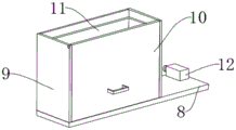
Referring to fig. 1-6, a full-automatic high-efficient multistage sewage purification device, includes water tank shell 1, and water tank shell 1 is the rectangle form, is equipped with first cavity in the water tank shell 1, and water tank shell 1 upper end is the opening form, and one side of water tank shell 1 is provided with water inlet 2, and domestic sewage passes through water inlet 2 and flows into in the first cavity, and one side of water tank shell 1 is provided with delivery port 3, and sewage is discharged from delivery port 3 after being purified treatment.
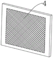
The inside wall of the water tank shell 1 is connected with three clapboards in a sliding way, the first chamber is divided into four areas by the three clapboards, the three clapboards are respectively fixedly connected with a first filter screen 4, a second filter screen 5 and an active carbon filter screen 6 through holes, the first filter screen 4 is close to the water inlet 2, the active carbon filter screen 6 is close to the water outlet 3, the area between the first filter screen 4 and the water inlet 2 is a primary treatment area which is used for intercepting some suspended matters with larger mass and precipitated silt, the area between the first filter screen 4 and the second filter screen 5 is a secondary treatment area, the flocculating agent is added in the secondary treatment area to destroy the stability of colloid, so that colloid particles are flocculated to generate flocculated matters and generate adsorption, the second filter screen 5 is used for intercepting the flocculated matters, the area between the second filter screen 5 and the active carbon filter screen 6 is a tertiary treatment area, the tertiary treatment region is through other pollutant elements in the active carbon filter screen 6 further adsorption filtration treatment sewage, and the region between active carbon filter screen 6 and the delivery port is water quality testing region for detect through the sewage after this purifier handles, whether can reach emission standard.
One side of the water tank shell 1 is fixedly connected with a first fixed block 20, the first fixed block 20 is connected with a second fixed block 21 matched with the first fixed block through a sliding groove in a sliding manner, the upper end of the second fixed block 21 is fixedly connected with a third box body 22, one side of the third box body 22 is fixedly connected with a connecting rod, the other end of the connecting rod is fixedly connected with the upper end of the first box body 9, the first box body 9 and the third box body 22 can simultaneously displace due to the arrangement of the connecting rod, a third chamber is arranged in the third box body 22, one side of the third box body 22 is in an open shape, a push plate 23 is connected in the third chamber in a sliding manner, the push plate 23 is used for pushing pollutants precipitated and accumulated on the first U-shaped plate 17 into the second box body 11, one side of the push plate 23 is fixedly connected with a hydraulic expansion bracket 24, the hydraulic expansion bracket 24 is the prior art and is not used here, and the other end of the hydraulic expansion bracket 24 is fixedly connected with the inner wall of the third chamber, the hydraulic telescopic frame 24 is used for providing a power source for the movement of the push plate 23, so that pollutants deposited and accumulated on the first U-shaped plate 17 can be pushed into the second box body 11.
One side of water tank shell 1 is provided with collecting box 7, collecting box 7 includes the slide rail of fixed connection in water tank shell one side, it has movable plate 8 to slide on the slide rail, bolt fixedly connected with motor 12 is passed through to movable plate 8 upper end, motor 12 is driving motor, because driving motor 12 is prior art, no longer describe herein, coaxial fixedly connected with gear in the drive shaft of motor 12, one side of water tank shell 1 is equipped with recess 13, fixedly connected with and the rack that the gear cooperation was used in recess 13, because motor 12 is fixed on movable plate 8, when motor 12's drive shaft rotated, under the cooperation of gear and rack, will drive movable plate 8 and take place the displacement, thereby drive second box 11 and also take place the displacement, make second box 11 not only can collect the rubbish that first treatment zone deposit, also can collect the rubbish that the second treatment zone deposits.
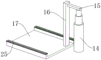
A hydraulic rod 14 is fixedly connected to the upper end of the moving plate 8, a connecting block 15 is fixedly connected to the upper end of the hydraulic rod 14, a first connecting plate 16 used in cooperation with the first connecting plate is clamped on the connecting block 15, a first U-shaped plate 17 is fixedly connected to the lower end of the first connecting plate 16, the first U-shaped plate 17 is located in a first cavity and used in cooperation with the first filter screen 4, the first U-shaped plate 17 is used for precipitating and collecting pollutants in a primary treatment area, the first U-shaped plate 17 located at the bottom of the first cavity is lifted up under the action of the hydraulic rod 14, the pollutants precipitated and accumulated on the surface of the first U-shaped plate 17 are pushed into a second box body 11 under the action of a push plate 23, a second U-shaped plate 18 used in cooperation with the second filter screen 5 is further arranged in the first cavity, the second U-shaped plate 18 is used for precipitating and collecting flocculates in a secondary treatment area, a second connecting plate 19 is fixedly connected to the upper end of the second U-shaped plate 18, be equipped with the breach that cooperation connecting block 15 used on second connecting plate 19, make second U template 18 also can use through second connecting plate 19 and connecting block 15 and the cooperation of hydraulic stem 14, deposit the flocculation thing of accumulation in the clearance collection secondary treatment region, the equal fixedly connected with brush 25 in 17 first U templates of first U template 17 upper end, in-process that 17 first U templates of first U template 17 rises, can clean the discarded object of first filter screen and second filter screen surface accumulation through the brush 25 that sets up, replace the manual work to go to clear up these rubbish, the effectual labour that has saved.
8 first boxes of upper end fixedly connected with 9 of movable plate, the inside second cavity that is equipped with of first box 9, first box 9 upper end is the opening form, one side of first box 9 is equipped with the opening with the second cavity intercommunication, be provided with open plate 10 in the opening, one side fixedly connected with handle of open plate 10, sliding connection has second box 11 in first box 9, second box 11 is inside to be equipped with the third cavity and the upper end is the opening form, second box 11 is used for collecting the regional rubbish that deposits the accumulation of primary treatment and secondary treatment, and when full at 11 splendid attire of second box, open the handle on the open plate 10 with the hand power, open plate 10, then pour the rubbish in the second box 11.
The working principle is that when the device is used, a first filter screen 4, a second filter screen 5 and an active carbon filter screen 6 are installed, a water inlet 2 is communicated with a sewage pipeline, a water outlet 3 is communicated with a discharge pipeline, a flocculating agent is added into a secondary treatment area, so that the sewage purification device can play a normal sewage purification role, when the sewage purification device is used for a period of time, garbage generated in the primary treatment area and the secondary treatment area in a first cavity needs to be cleaned, a hydraulic rod 14 rises at the moment, a first connecting plate 16 and a first U-shaped plate 17 are driven to rise to a proper height, a hydraulic expansion bracket 24 pushes a push plate 23 to move, the push plate 23 pushes the garbage deposited and accumulated at the upper end of the first U-shaped plate 17 into a second box body 11, and in the rising process of the first U-shaped plate 17, a brush 25 fixedly connected to the first U-shaped plate 17 can play a role in cleaning the first filter screen 4, after the garbage on the first U-shaped plate 17 is cleaned, the hydraulic expansion bracket 24 drives the push plate 23 to return to the initial position, the hydraulic rod 14 descends to enable the first U-shaped plate 17 to return to the initial position, then the movable plate 8 drives the first box body 9, the second box body 11 and the hydraulic rod 14 to move to the position matched with the secondary treatment area under the action of the motor 12, the third box body 22 is driven to move to the position matched with the secondary treatment area through the connecting rod in the moving process of the first box body 9, then the hydraulic rod 14 ascends, the second U-shaped plate 18 is driven to ascend to a proper position under the matching of the connecting block 15 and the second connecting plate 19, the hairbrush 25 fixedly connected with the upper end of the second U-shaped plate 18 can play a role in cleaning the first filter screen 4 and the second filter screen 5 in the ascending process of the second U-shaped plate 18, and at the moment, the hydraulic expansion bracket 24 pushes the push plate 23 to move, make push pedal 23 push away the second box 11 with the rubbish that second U template 18 upper end sediment accumulation, after the clearance finishes, hydraulic telescoping rack 24 drives push pedal 23 and gets back to initial position, hydraulic stem 14 descends, make second U template 18 return to initial position, under the effect of motor 12, drive movable plate 8 and first box 9 and second box 11 and third box 22 and get back to initial position, when second box 11 splendid attire was collected full rubbish, open the handle on the plywood 10 with the hand power, open plywood 10, then pour the rubbish in the second box 11.
The above description is only for the preferred embodiment of the present invention, but the scope of the present invention is not limited thereto, and any person skilled in the art should be considered to be within the technical scope of the present invention, and equivalent alternatives or modifications according to the technical solution of the present invention and the inventive concept thereof should be covered by the scope of the present invention.
Claims (6)
1. The utility model provides a full-automatic high-efficient multistage effluent treatment plant, includes water tank shell (1), its characterized in that, water tank shell (1) is the rectangle form, be equipped with first cavity in water tank shell (1), water tank shell (1) upper end is the opening form, one side of water tank shell (1) is provided with water inlet (2), one side of water tank shell (1) is provided with delivery port (3), sliding connection has three baffle on the inside wall of water tank shell (1), three the baffle is respectively through-hole fixedly connected with first filter screen (4) and second filter screen (5) and active carbon filter screen (6), first filter screen (4) are close to water inlet (2), active carbon filter screen (6) are close to delivery port (3), one side of water tank shell (1) is provided with collecting box (7), be equipped with the actuating mechanism who uses with it cooperation on collecting box (7), the collecting box (7) is provided with a lifting mechanism matched with the collecting box, and one side of the water tank shell (1) is provided with a pushing mechanism.
2. The full-automatic efficient multistage sewage purification device according to claim 1, wherein the collection box (7) comprises a moving plate (8) slidably connected to one side of the water tank housing (1), a first box body (9) is fixedly connected to the upper end of the moving plate (8), a second cavity is arranged inside the first box body (9), the upper end of the first box body (9) is open, an opening communicated with the second cavity is arranged on one side of the first box body (9), a split plate (10) is arranged in the opening, a handle is fixedly connected to one side of the split plate (10), a second box body (11) is slidably connected to the first box body (9), a third cavity is arranged inside the second box body (11), and the upper end of the third cavity is open.
3. The full-automatic high-efficiency multistage sewage purification device according to claim 2, wherein the driving mechanism comprises a motor (12) fixedly connected to the upper end of the moving plate (8) through a bolt, a gear is coaxially and fixedly connected to a driving shaft of the motor (12), a groove (13) is formed in one side of the water tank housing (1), and a rack matched with the gear is fixedly connected to the inside of the groove (13).
4. The full-automatic high-efficiency multistage sewage purification device according to claim 2, the lifting mechanism comprises a hydraulic rod (14) fixedly connected to the upper end of the movable plate (8) through a bolt, the upper end of the hydraulic rod (14) is fixedly connected with a connecting block (15), a first connecting plate (16) matched with the connecting block (15) for use is clamped on the connecting block (15), the lower end of the first connecting plate (16) is fixedly connected with a first U-shaped plate (17), the first U-shaped plate (17) is positioned in the first cavity and is matched with the first filter screen (4) for use, a second U-shaped plate (18) used for being matched with the second filter screen (5) is also arranged in the first cavity, the upper end of the second U-shaped plate (18) is fixedly connected with a second connecting plate (19), and a notch matched with the connecting block (15) for use is arranged on the second connecting plate (19).
5. The full-automatic high-efficiency multistage sewage purification device according to claim 2, the pushing mechanism comprises a first fixed block (20) fixedly connected with one side of the water tank shell (1), the first fixed block (20) is connected with a second fixed block (21) matched with the first fixed block in a sliding way, the upper end of the second fixed block (21) is fixedly connected with a third box body (22), one side of the third box body (22) is fixedly connected with a connecting rod, the other end of the connecting rod is fixedly connected with the upper end of the first box body (9), a third chamber is arranged in the third box body (22), one side of the third box body (22) is open, a push plate (23) is connected in the third chamber in a sliding way, one side fixedly connected with hydraulic telescoping frame (24) of push pedal (23), the other end and the inner wall fixed connection of third chamber of hydraulic telescoping frame (24).
6. The full-automatic high-efficiency multistage sewage purification device according to claim 4, wherein the upper ends of the first U-shaped plate (17) and the second U-shaped plate (18) are fixedly connected with a brush (25).
Priority Applications (1)
| Application Number | Priority Date | Filing Date | Title |
|---|---|---|---|
| CN202121374050.8U CN215539111U (en) | 2021-06-21 | 2021-06-21 | Full-automatic high-efficient multistage sewage purification device |
Applications Claiming Priority (1)
| Application Number | Priority Date | Filing Date | Title |
|---|---|---|---|
| CN202121374050.8U CN215539111U (en) | 2021-06-21 | 2021-06-21 | Full-automatic high-efficient multistage sewage purification device |
Publications (1)
| Publication Number | Publication Date |
|---|---|
| CN215539111U true CN215539111U (en) | 2022-01-18 |
Family
ID=79818957
Family Applications (1)
| Application Number | Title | Priority Date | Filing Date |
|---|---|---|---|
| CN202121374050.8U Active CN215539111U (en) | 2021-06-21 | 2021-06-21 | Full-automatic high-efficient multistage sewage purification device |
Country Status (1)
| Country | Link |
|---|---|
| CN (1) | CN215539111U (en) |
Cited By (1)
| Publication number | Priority date | Publication date | Assignee | Title |
|---|---|---|---|---|
| CN116832501A (en) * | 2023-08-31 | 2023-10-03 | 山西振钢生物科技股份有限公司 | Pretreatment device for water sedimentation of sebacic acid mother liquor |
-
2021
- 2021-06-21 CN CN202121374050.8U patent/CN215539111U/en active Active
Cited By (2)
| Publication number | Priority date | Publication date | Assignee | Title |
|---|---|---|---|---|
| CN116832501A (en) * | 2023-08-31 | 2023-10-03 | 山西振钢生物科技股份有限公司 | Pretreatment device for water sedimentation of sebacic acid mother liquor |
| CN116832501B (en) * | 2023-08-31 | 2023-11-17 | 山西振钢生物科技股份有限公司 | Pretreatment device for water sedimentation of sebacic acid mother liquor |
Similar Documents
| Publication | Publication Date | Title |
|---|---|---|
| CN110117102A (en) | A kind of sewage disposal device with automatic clearing function | |
| CN215539111U (en) | Full-automatic high-efficient multistage sewage purification device | |
| CN206771467U (en) | A kind of wet lampblack depuration equipment of automated cleaning | |
| CN212610022U (en) | But effluent treatment plant is used in recycled paper production of self-cleaning | |
| CN212523238U (en) | Sewage treatment device convenient to clean | |
| CN211328336U (en) | Chemical sewage treatment device | |
| CN112811501A (en) | A compound carbon source apparatus for producing for waste water treatment | |
| CN215559489U (en) | Sewage treatment purifier of municipal works construction | |
| CN210751573U (en) | Sewage treatment plant for environmental protection | |
| CN212770152U (en) | Filter equipment for building engineering | |
| CN213253268U (en) | Industrial sewage treatment garbage cleaning device | |
| CN212198946U (en) | Integration MBR membrane sewage treatment device | |
| CN113304540A (en) | Domestic waste sewage purification device | |
| CN214680390U (en) | Sewage purification treatment device | |
| CN218188189U (en) | Energy-concerving and environment-protective multi-functional municipal sewage treatment plant | |
| CN218339336U (en) | Fly ash collecting device | |
| CN210631795U (en) | Urban environment-friendly sewage collection and purification device | |
| CN217188111U (en) | Construction sewage treatment ware case | |
| CN218166237U (en) | Utilize sewage filter equipment of useless active carbon core of danger | |
| CN220878060U (en) | River course ecological environment administers device | |
| CN218232088U (en) | Primary filtering device for sewage treatment | |
| CN220572766U (en) | High-efficient water pollution treatment device | |
| CN210206052U (en) | River sewage treatment equipment | |
| CN212141711U (en) | Based on waste water recovery unit for water purifier | |
| CN113402119B (en) | Energy-saving environment-friendly domestic sewage treatment device |
Legal Events
| Date | Code | Title | Description |
|---|---|---|---|
| GR01 | Patent grant | ||
| GR01 | Patent grant |