CN215522899U - Gas drainer with electric heating function - Google Patents
Gas drainer with electric heating function Download PDFInfo
- Publication number
- CN215522899U CN215522899U CN202121402314.6U CN202121402314U CN215522899U CN 215522899 U CN215522899 U CN 215522899U CN 202121402314 U CN202121402314 U CN 202121402314U CN 215522899 U CN215522899 U CN 215522899U
- Authority
- CN
- China
- Prior art keywords
- drainer
- drain pipe
- electric heating
- heating function
- rod
- Prior art date
- Legal status (The legal status is an assumption and is not a legal conclusion. Google has not performed a legal analysis and makes no representation as to the accuracy of the status listed.)
- Active
Links
Images


Landscapes
- Vaporization, Distillation, Condensation, Sublimation, And Cold Traps (AREA)
Abstract
The utility model discloses a gas drainer with an electric heating function, which comprises a drainer body, wherein an installation rod is fixedly installed at the top of the right side of the drainer body, a connecting plate is fixedly installed at the bottom of the right side of the drainer body, a drain pipe is arranged at the right side of the drainer body, a rotating rod is arranged at the bottom of the installation rod, a threaded groove is formed in the rotating rod, and a threaded rod is rotatably connected in the threaded groove through threads. The gas drainer is provided with the drainer body to condense gas, the motor is arranged through the mounting groove, and the rotating rod is driven through the motor, so that the problems that the gas drainer is easy to freeze when working, the equipment cannot work normally, the drainer needs to be heated to discharge water flow, the gas drainer is inconvenient to disassemble during maintenance, and the practicability of the gas drainer is greatly reduced are solved.
Description
Technical Field
The utility model relates to the technical field of gas drainers, in particular to a gas drainer with an electric heating function.
Background
The coal gas drainer has the advantages that the coal gas drainer is used for collecting and discharging condensed water in a coal gas pipeline, the common coal gas drainer has the following problems in use, when the production working condition changes to enable the coal gas pressure to rise a lot instantly, the coal gas drainer is easy to be punctured to cause a large amount of coal gas to leak, serious accidents are caused, when the coal gas pressure fluctuates frequently, the coal gas drainer cannot automatically replenish water, if manual water replenishing is not timely, coal gas leaks, and fires or personnel coal gas poisoning are easily caused.
In the low temperature environment in the north, the drainer freezes the phenomenon appears easily in coal gas drainer during operation, causes equipment can not normally work, needs to heat the drainer and makes rivers discharge to when maintaining, dismantle inconveniently, greatly reduced coal gas drainer's practicality.
Disclosure of Invention
The utility model aims to provide a gas drainer with an electric heating function, which has the advantages of convenience in maintenance and heating, and solves the problems that the gas drainer is easy to freeze when in work, so that equipment cannot work normally, the drainer needs to be heated to discharge water flow, the gas drainer is inconvenient to disassemble when in maintenance, and the practicability of the gas drainer is greatly reduced.
In order to achieve the purpose, the utility model provides the following technical scheme: the coal gas drainer with the electric heating function comprises a drainer body, wherein the top of the right side of the drainer body is fixedly provided with a mounting rod, the bottom of the right side of the drainer body is fixedly provided with a connecting plate, the right side of the drainer body is provided with a drain pipe, the bottom of the mounting rod is provided with a rotating rod, the inside of the rotating rod is provided with a thread groove, the inside of the thread groove is connected with a threaded rod through thread rotation, the bottom of the threaded rod is fixedly provided with a clamping block, both sides of the center of the top of the connecting plate are fixedly provided with fixing rods, a spring is fixedly arranged at the center of the top of the connecting plate, an installation groove is arranged at the center of the bottom of the installation rod, the inside fixed mounting of mounting groove has the motor, the holding tank has all been seted up to the both sides in drain pipe inner chamber, the inside fixed mounting of holding tank has the hot plate.
Preferably, the output shaft of the motor is fixedly connected with the top of the rotating rod, and the two sides of the bottom of the clamping block are fixedly provided with limiting blocks.
Preferably, a first sliding groove is formed in the right side of the interior of the drainer body, a second sliding block is connected to the interior of the first sliding groove in a sliding mode, and the right side of the bottom of the second sliding block is fixedly connected with the left side of the top of the clamping block.
Preferably, two second limiting grooves are formed in the top of the surface of the drain pipe, and the limiting blocks penetrate through the second limiting grooves to the inside of the drain pipe.
Preferably, a second sliding groove is formed in one side, close to the fixed rod relatively, of the fixed rod, and a first sliding block is connected to the inside of the second sliding groove in a sliding mode.
Preferably, a limiting plate is fixedly mounted on one side, close to the first sliding block, of the first sliding block, the bottom of the limiting plate is fixedly connected with the top of the spring, and the top of the limiting plate is movably connected with the bottom of the drain pipe.
Preferably, two first limiting grooves are formed in the bottom of the surface of the drain pipe, and the fixing rod penetrates through the inside of the drain pipe through the first limiting grooves.
Compared with the prior art, the utility model has the following beneficial effects:
1. the gas drainer comprises a drainer body, a motor, a rotating rod, a drain pipe, a threaded rod, a limiting block, a containing groove, a heating plate, a spring, a limiting plate and a spring.
2. According to the utility model, the drain pipe is limited by arranging the limiting block, water is guided by arranging the drain pipe, the second sliding block is limited by arranging the first sliding groove, the second sliding block is prevented from shaking in the moving process, the limiting block is accommodated and limited by arranging the second limiting groove, the first sliding block is limited by arranging the second sliding groove, the first sliding block is prevented from shaking in the moving process, the limiting plate is limited by arranging the first sliding block, the limiting plate is prevented from shaking in the moving process, the fixing rod is accommodated by arranging the first limiting groove, and the drain pipe is limited by arranging the fixing rod.
Drawings
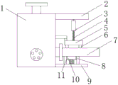
FIG. 1 is a schematic external structural view of an embodiment of the present invention;
FIG. 2 is a schematic diagram of the internal structure of the embodiment of the present invention;
fig. 3 is a schematic view of a drain pipe structure in an embodiment of the utility model.
In the figure: 1. a drainer body; 2. mounting a rod; 3. rotating the rod; 4. a threaded rod; 5. a clamping block; 6. a limiting block; 7. a drain pipe; 8. fixing the rod; 9. a connecting plate; 10. a limiting plate; 11. a first slider; 12. heating plates; 13. a first chute; 14. a second slider; 15. mounting grooves; 16. a motor; 17. a thread groove; 18. a first limit groove; 19. accommodating grooves; 20. a second chute; 21. a spring; 22. a second limit groove.
Detailed Description
The technical solutions in the embodiments of the present invention will be clearly and completely described below with reference to the drawings in the embodiments of the present invention, and it is obvious that the described embodiments are only a part of the embodiments of the present invention, and not all of the embodiments. All other embodiments, which can be derived by a person skilled in the art from the embodiments given herein without making any creative effort, shall fall within the protection scope of the present invention.
In the description herein, it is to be understood that the terms "center," "upper," "lower," "front," "rear," "left," "right," "vertical," "horizontal," "top," "bottom," "inner," "outer," and the like are used in the orientations and positional relationships indicated in the drawings to facilitate the description of the patent and to simplify the description, but do not indicate or imply that the referenced device or element must have a particular orientation, be constructed and operated in a particular orientation, and thus are not to be considered limiting of the patent. In the description of the present application, it should be noted that unless otherwise explicitly stated or limited, the terms "mounted," "connected," and "disposed" are to be construed broadly and can, for example, be fixedly connected, disposed, detachably connected, disposed, or integrally connected and disposed. The specific meaning of the above terms in this patent may be understood by those of ordinary skill in the art as appropriate.
Referring to fig. 1-3, the gas drainer with an electric heating function comprises a drainer body 1, wherein a mounting rod 2 is fixedly mounted at the top of the right side of the drainer body 1, a connecting plate 9 is fixedly mounted at the bottom of the right side of the drainer body 1, a drain pipe 7 is arranged at the right side of the drainer body 1, a rotating rod 3 is arranged at the bottom of the mounting rod 2, a thread groove 17 is formed in the rotating rod 3, the interior of the thread groove 17 is rotatably connected with a threaded rod 4 through threads, a clamping block 5 is fixedly mounted at the bottom of the threaded rod 4, fixing rods 8 are fixedly mounted at both sides of the center of the top of the connecting plate 9, a spring 21 is fixedly mounted at the center of the top of the connecting plate 9, a mounting groove 15 is formed at the center of the bottom of the mounting rod 2, a motor 16 is fixedly mounted in the mounting groove 15, accommodating grooves 19 are formed at both sides of the inner cavity of the drain pipe 7, and a heating plate 12 is fixedly mounted in the accommodating grooves 19, the coal gas is condensed by arranging the drainer body 1, the motor 16 is installed by arranging the installation groove 15, the rotating rod 3 is driven by arranging the motor 16, water is discharged by arranging the drain pipe 7, the threaded rod 4 is driven by arranging the rotating rod 3, the limit block 6 is installed by arranging the fixture block 5, the drain pipe 7 is fixed by arranging the limit block 6, the heating plate 12 is installed by arranging the holding groove 19, the water in the drain pipe 7 is heated by arranging the heating plate 12, the limit plate 10 is limited by arranging the spring 21, the output shaft of the motor 16 is fixedly connected with the top of the rotating rod 3, the limit blocks 6 are fixedly installed on both sides of the bottom of the fixture block 5, the drain pipe 7 is limited by arranging the limit blocks 6, the water is guided by arranging the drain pipe 7, the first chute 13 is arranged on the right side in the drainer body 1, the inside of the first sliding groove 13 is slidably connected with a second sliding block 14, the right side of the bottom of the second sliding block 14 is fixedly connected with the left side of the top of the clamping block 5, the second sliding block 14 is limited by arranging the first sliding groove 13, the second sliding block 14 is prevented from shaking in the moving process, two second limiting grooves 22 are formed in the top of the surface of the drain pipe 7, the limiting block 6 penetrates into the drain pipe 7 through the second limiting grooves 22, the limiting block 6 is accommodated and limited by arranging the second limiting grooves 22, the second sliding grooves 20 are formed in the sides, which are relatively close to the fixing rods 8, of the second sliding grooves 20, the first sliding block 11 is slidably connected in the second sliding grooves 20, the first sliding block 11 is limited by arranging the second sliding grooves 20, the first sliding block 11 is prevented from shaking in the moving process, a limiting plate 10 is fixedly installed on the side, which is relatively close to the first sliding block 11, the bottom of the limiting plate 10 is fixedly connected with the top of the spring 21, the top of limiting plate 10 and the bottom swing joint of drain pipe 7 carry on spacingly to limiting plate 10 through setting up first slider 11, prevent that limiting plate 10 from taking place to rock at the in-process that removes, two first spacing grooves 18 have been seted up to the bottom on drain pipe 7 surface, and dead lever 8 runs through the inside to drain pipe 7 through first spacing groove 18, holds dead lever 8 through setting up first spacing groove 18, carries on spacingly through setting up dead lever 8 to drain pipe 7.
During the use, when heating drain pipe 7, open hot plate 12, heat the inside flowing water of drain pipe 7, prevent to freeze, when dismantling drain pipe 7, open motor 16, drive dwang 3 through motor 16 and rotate, under the effect of screw thread for threaded rod 4 drives second slider 14, fixture block 5 and stopper 6 rebound, under the effect of spring 21, make first slider 11 drive limiting plate 10 rebound, thereby dismantle the maintenance with drain pipe 7 jack-up.
Although embodiments of the present invention have been shown and described, it will be appreciated by those skilled in the art that changes, modifications, substitutions and alterations can be made in these embodiments without departing from the principles and spirit of the utility model, the scope of which is defined in the appended claims and their equivalents.
Claims (7)
1. Gas drainer with electric heating function, including drainer body (1), its characterized in that: the water drainer is characterized in that an installation rod (2) is fixedly installed at the top of the right side of the water drainer body (1), a connecting plate (9) is fixedly installed at the bottom of the right side of the water drainer body (1), a water drain pipe (7) is arranged at the right side of the water drainer body (1), a rotating rod (3) is arranged at the bottom of the installation rod (2), a thread groove (17) is formed in the rotating rod (3), a threaded rod (4) is rotatably connected to the inside of the thread groove (17) through threads, a fixture block (5) is fixedly installed at the bottom of the threaded rod (4), fixing rods (8) are fixedly installed on two sides of the center of the top of the connecting plate (9), a spring (21) is fixedly installed at the center of the top of the connecting plate (9), an installation groove (15) is formed in the center of the bottom of the installation rod (2), and a motor (16) is fixedly installed in the inside of the installation groove (15), holding tank (19) have all been seted up to the both sides of drain pipe (7) inner chamber, the inside fixed mounting of holding tank (19) has hot plate (12).
2. The gas drainer with the electric heating function as claimed in claim 1, wherein: the output shaft of motor (16) and the top fixed connection of dwang (3), equal fixed mounting in both sides of fixture block (5) bottom has stopper (6).
3. The gas drainer with the electric heating function as claimed in claim 1, wherein: first spout (13) have been seted up on the inside right side of drainer body (1), the inside sliding connection of first spout (13) has second slider (14), the right side of second slider (14) bottom and the left side fixed connection at fixture block (5) top.
4. The gas drainer with the electric heating function as claimed in claim 2, wherein: two second spacing grooves (22) have been seted up at the top on drain pipe (7) surface, stopper (6) run through to the inside of drain pipe (7) through second spacing groove (22).
5. The gas drainer with the electric heating function as claimed in claim 1, wherein: second spout (20) have all been seted up to the one side that dead lever (8) are close to relatively, the inside sliding connection of second spout (20) has first slider (11).
6. The gas drainer with the electric heating function as claimed in claim 5, wherein: one side that first slider (11) is close to relatively has limiting plate (10), the bottom of limiting plate (10) and the top fixed connection of spring (21), the top of limiting plate (10) and the bottom swing joint of drain pipe (7).
7. The gas drainer with the electric heating function as claimed in claim 1, wherein: two first limiting grooves (18) are formed in the bottom of the surface of the drain pipe (7), and the fixing rod (8) penetrates through the inside of the drain pipe (7) through the first limiting grooves (18).
Priority Applications (1)
| Application Number | Priority Date | Filing Date | Title |
|---|---|---|---|
| CN202121402314.6U CN215522899U (en) | 2021-06-23 | 2021-06-23 | Gas drainer with electric heating function |
Applications Claiming Priority (1)
| Application Number | Priority Date | Filing Date | Title |
|---|---|---|---|
| CN202121402314.6U CN215522899U (en) | 2021-06-23 | 2021-06-23 | Gas drainer with electric heating function |
Publications (1)
| Publication Number | Publication Date |
|---|---|
| CN215522899U true CN215522899U (en) | 2022-01-14 |
Family
ID=79809821
Family Applications (1)
| Application Number | Title | Priority Date | Filing Date |
|---|---|---|---|
| CN202121402314.6U Active CN215522899U (en) | 2021-06-23 | 2021-06-23 | Gas drainer with electric heating function |
Country Status (1)
| Country | Link |
|---|---|
| CN (1) | CN215522899U (en) |
-
2021
- 2021-06-23 CN CN202121402314.6U patent/CN215522899U/en active Active
Similar Documents
| Publication | Publication Date | Title |
|---|---|---|
| CN203399464U (en) | Closed-type circulating cooling device | |
| CN209052385U (en) | Filling apparatus is used in a kind of drip-proof anti-icing fluid production | |
| CN209589158U (en) | A kind of highly sensitive remote transmitting water meter with low temperature antifreeze function | |
| CN215522899U (en) | Gas drainer with electric heating function | |
| CN103985511B (en) | Install the transformer heat exchanger of oil cleaner additional | |
| CN2275240Y (en) | Quick freeze-thawing test device for concrete | |
| CN214579079U (en) | Anti-freezing check valve | |
| CN208266815U (en) | A kind of hard water-stopping steel gate of PGYR electric heating | |
| CN112304846A (en) | Engineering building material waterproof detection device and monitoring method thereof | |
| CN208733732U (en) | A kind of outdoor anti-freezing fire hydrant | |
| CN213274426U (en) | Anti-freezing water meter | |
| CN111255449A (en) | Sampling hole structure for oil pipe | |
| CN112798491A (en) | Fractured rock mass permeability coefficient evolution test system | |
| CN220706421U (en) | Low-temperature-resistant stop valve | |
| CN101429951A (en) | Closed-loop self-cooling units | |
| CN213254505U (en) | Medicine stability test box low temperature device | |
| CN219368067U (en) | Sealing structure for refrigerant filling | |
| CN219282464U (en) | Anti-freezing gate valve with self-heating function | |
| CN215569781U (en) | Energy-saving anti-leakage device of gas drainer | |
| CN213869094U (en) | Anti-freezing device for water conservancy and hydropower equipment | |
| CN116576512B (en) | Waterproof structure of external wall-mounted air conditioner mounting port of energy storage container | |
| CN114321398B (en) | Outlet valve of low-pressure hot water circulating pump | |
| CN212575701U (en) | Sewage source heat pump blowdown structure of loosing | |
| CN218818945U (en) | Anti-freezing device for pipeline construction | |
| CN208859025U (en) | A kind of water conservancy valve of easy access |
Legal Events
| Date | Code | Title | Description |
|---|---|---|---|
| GR01 | Patent grant | ||
| GR01 | Patent grant |