CN215516136U - Coiling device for power distribution engineering - Google Patents
Coiling device for power distribution engineering Download PDFInfo
- Publication number
- CN215516136U CN215516136U CN202120119152.9U CN202120119152U CN215516136U CN 215516136 U CN215516136 U CN 215516136U CN 202120119152 U CN202120119152 U CN 202120119152U CN 215516136 U CN215516136 U CN 215516136U
- Authority
- CN
- China
- Prior art keywords
- winding
- power distribution
- motor
- fixedly arranged
- sliding groove
- Prior art date
- Legal status (The legal status is an assumption and is not a legal conclusion. Google has not performed a legal analysis and makes no representation as to the accuracy of the status listed.)
- Active
Links
Images

Abstract
The utility model relates to the technical field of power distribution engineering, in particular to a winding device for power distribution engineering. The device simple structure, convenient operation uses, and the winding displacement device can realize the positive and negative rotation of motor, can realize piling up of cable simultaneously and wind attaching the range, has avoided the part of cable to wind attaching and the confusion that causes, has increased the cable and has wound the orderliness of attaching, has increased the convenience that the staff used.
Description
Technical Field
The utility model relates to the technical field of power distribution projects, in particular to a winding device for the power distribution projects.
Background
The work of the power distribution project can be divided into a plurality of items, including the installation of electrical control equipment, the installation of cabling equipment, the recovery of cables needing to be replaced, the laying of new cables and the installation of elements, and in the implementation process of the power distribution project, the used cables need to be rolled on a rolling disc to be carried.
The existing mode is to roll up them on the take-up reel with the spiral device for the cable, and this kind of spiral mode will cause when receiving the line, and the line of rolling will concentrate the winding in the local of take-up reel, can't realize that the even winding of cable conductor is on the take-up reel, has the line of rolling to appear mixed and disorderly or the phenomenon of knoing, and inconvenient people's transport brings inconvenience for the user simultaneously. Therefore, a winding device for power distribution engineering is provided by those skilled in the art to solve the problems in the background art.
SUMMERY OF THE UTILITY MODEL
The present invention is directed to a winding device for power distribution engineering to solve the above problems.
In order to achieve the purpose, the utility model provides the following technical scheme: a winding device for power distribution engineering comprises a bottom plate, wherein supporting side plates are fixedly arranged at two ends of one side of the bottom plate, a winding disc is arranged between the supporting side plates, a rotating shaft is fixedly arranged on one side of the winding disc, one end, far away from the winding disc, of the rotating shaft penetrates through the supporting side plates and extends towards the other side of the rotating shaft to be connected with an output end of a first motor, and a winding displacement device is arranged on one side of the winding disc;
the wire arranging device comprises two supporting oblique rods fixedly arranged on one side of each supporting side plate, a sliding groove is fixedly arranged between the two supporting oblique rods, a threaded rod is arranged in the sliding groove, one end of the threaded rod penetrates through the sliding groove and extends outwards to be connected with the output end of a second motor, a sliding block is sleeved on the threaded rod in the sliding groove and is positioned on the threaded rod, an inserting cylinder is fixedly arranged in the middle of one side of the sliding block, an inserting rod is arranged in the inserting cylinder in a sliding manner, one end of the inserting rod is connected with the inside of the inserting cylinder through a spring, the two sides of the inserting rod are connected with the inner wall of the inserting cylinder through a limiting device, a fixing ring is fixedly arranged at one end of the inserting rod, away from the inserting cylinder, extrusion blocks are fixedly arranged on the two sides of the sliding block, a pressure sensor is fixedly arranged on one side of the extrusion blocks and positioned on the inner wall of the sliding groove, and the pressure sensor is electrically connected with a controller, the second motor is electrically connected with the controller.
As a further aspect of the utility model: the rotating shaft is connected with the penetrating position of the supporting side plate through a bearing sleeve, and one end, far away from the rotating shaft, of the winding disc is connected with the supporting side plate through a bearing seat.
As a further aspect of the utility model: a supporting table is arranged on one side below the first motor, and one end of the supporting table is fixedly connected with the bottom plate.
As a further aspect of the utility model: a supporting plate is arranged below the second motor, and one end of the supporting plate is fixedly connected with one side of the supporting inclined rod.
As a further aspect of the utility model: the both sides of slider just are located all the cover is equipped with damping spring on the threaded rod, one side of bottom plate is fixed to be equipped with quantity and is four removal wheels, it is the form setting of rectangular array to remove the wheel.
As a further aspect of the utility model: the limiting device comprises a fixed push plate arranged at one end of the inserting rod, limiting sliding blocks are fixedly arranged at two ends of the push plate, the limiting sliding blocks are slidably arranged in the limiting sliding grooves, and one side of each limiting sliding groove is fixedly connected with the inner wall of the corresponding inserting cylinder.
Compared with the prior art, the utility model has the beneficial effects that: the rotation of rolling dish will be driven in the start-up of first motor, the rotation of rolling dish will realize the cable around attaching on the rolling dish, the second motor starts, drive winding displacement device and pull to the cable, realize that the cable is orderly around attaching on the rolling dish, inserted bar and insert through spring coupling between the section of thick bamboo, can realize piling up of cable around attaching, the device simple structure, convenient operation uses, the part of having avoided the cable is around attaching and the scattered in disorder that causes, the orderliness that the cable was around attaching has been increased, the convenience that the staff used has been increased.
Drawings
FIG. 1 is a schematic structural diagram of a winding device for power distribution engineering;
fig. 2 is a rear view of a winding device for power distribution works;
fig. 3 is a schematic structural view of a limiting device in a winding device for power distribution engineering.
In the figure: 1. a base plate; 2. supporting the side plates; 3. a winding disc; 4. a rotating shaft; 5. a first motor; 6. supporting the diagonal rods; 7. a chute; 8. a threaded rod; 9. a second motor; 10. a slider; 11. inserting a cylinder; 12. inserting a rod; 13. a spring; 14. a fixing ring; 15. extruding the block; 16. a pressure sensor; 17. a controller; 18. a bearing housing; 19. a support table; 20. a limiting slide block; 21. a limiting chute; 22. the wheel is moved.
Detailed Description
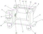
Referring to fig. 1-3, in an embodiment of the present invention, a winding device for a power distribution project includes a bottom plate 1, supporting side plates 2 are fixedly disposed at both ends of one side of the bottom plate 1, a winding plate 3 is disposed between the supporting side plates 2, a rotating shaft 4 is fixedly disposed at one side of the winding plate 3, one end of the rotating shaft 4, which is far away from the winding plate 3, penetrates through the supporting side plates 2 and extends to the other side thereof to be connected with an output end of a first motor 5, and a winding displacement device is disposed at one side of the winding plate 3;
in fig. 1, 2 and 3: the wire arranging device comprises supporting oblique rods 6 fixedly arranged on one sides of two supporting side plates 2, a sliding groove 7 is fixedly arranged between the two supporting oblique rods 6, a threaded rod 8 is arranged in the sliding groove 7, one end of the threaded rod 8 penetrates through the sliding groove 7 and extends outwards to be connected with the output end of a second motor 9, a sliding block 10 is sleeved in the sliding groove 7 and positioned on the threaded rod 8 in a threaded manner, an inserting cylinder 11 is fixedly arranged in the middle of one side of the sliding block 10, an inserting rod 12 is arranged in the inserting cylinder 11 in a sliding manner, one end of the inserting rod 12 is connected with the inside of the inserting cylinder 11 through a spring 13, two sides of the inserting rod 12 are connected with the inner wall of the inserting cylinder 11 through limiting devices, a fixing ring 14 is fixedly arranged at one end of the inserting rod 12 far away from the inserting cylinder 11, extrusion blocks 15 are fixedly arranged on two sides of the sliding block 10, a pressure sensor 16 is fixedly arranged on one side of the extrusion blocks 15 and positioned on the inner wall of the sliding groove 7, and the pressure sensor 16 is electrically connected with a controller 17, the second motor 9 is electrically connected to the controller 17.
In fig. 1 and 2: the penetrating position of the rotating shaft 4 and the supporting side plate 2 is connected through a bearing sleeve 18, one end, far away from the rotating shaft 4, of the winding disc 3 is connected with the supporting side plate 2 through a bearing seat, and friction force between the penetrating positions of the rotating shaft 4 and the supporting side plate 2 is reduced.
In fig. 1 and 2: one side of the lower part of the first motor 5 is provided with a supporting table 19, one end of the supporting table 19 is fixedly connected with the bottom plate 1, the first motor 5 can be supported, the safety of placing the first motor 5 is improved, and the first motor 5 is prevented from being placed in a suspended mode.
In fig. 1 and 2: the below of second motor 9 is equipped with the backup pad, and the effect that can start the support to second motor 9 can be to one side fixed connection of support down tube 6 to the one end of backup pad, avoids the unsettled of second motor 9 to place.
In FIG. 2: the both sides of slider 10 just are located all the cover and are equipped with damping spring on the threaded rod 8, can remove the effect that the in-process played the buffering to slider 10, avoid great impact to cause the damage to pressure sensor 16, one side of bottom plate 1 is fixed to be equipped with quantity and is four removal wheel 22, removes the form setting that wheel 22 is the rectangle array, removes wheel 22 and can increase the flexibility that removes the in-process, reduces people's transport.
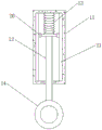
In FIG. 3: stop device is including the fixed push pedal of locating inserted bar 12 one end, and the push pedal both ends are all fixed and are equipped with limiting slide block 20, and limiting slide block 20 slides and locates limiting slide groove 21's inside, and one side of limiting slide groove 21 and the inner wall fixed connection of inserting a section of thick bamboo 11 increase the flexible in-process stability of inserted bar 12.
The working principle of the utility model is as follows: when the cable winding device is used specifically, one end of a cable firstly penetrates through the fixing ring 14, then one end of the winding and winding disc 3 is fixedly wound, then the first motor 5 and the second motor 9 are started, the first motor 5 is started to drive the winding disc 3 to rotate, the winding disc 3 rotates to realize that the cable is wound on the winding disc 3, due to the starting of the second motor 9, the second motor 9 is started to drive the threaded rod 8 to rotate, the threaded rod 8 rotates to drive the sliding block 10 to move in the sliding groove 7, so that the inserting cylinder 11 and the inserting rod 12 are driven to move, the fixing ring 14 is driven to move, the fixing ring 14 can realize orderly traction on the cable, the cable is wound on the winding disc 3, the cable is arranged in order, and meanwhile, due to the connection between the inserting rod 12 and the inserting cylinder 11 through the spring 13, the stacking winding of the cable can be realized, when the device is used, the second motor 9 is a true reverse rotation motor, when the extrusion block 15 on one side of the sliding block 10 and the pressure sensor 16 at the end part of the sliding groove 7 extrude to generate pressure, the controller 17 controls the second motor 9 to rotate reversely at the moment, and therefore stacking, winding and arranging of cables are achieved.
The above description is only for the preferred embodiment of the present invention, but the scope of the present invention is not limited thereto, and any person skilled in the art should be considered to be within the scope of the present invention, and the technical solutions and the utility model concepts of the present invention are equivalent to or changed within the scope of the present invention.
Claims (6)
1. A winding device for power distribution engineering comprises a bottom plate (1), and is characterized in that supporting side plates (2) are fixedly arranged at two ends of one side of the bottom plate (1), a winding disc (3) is arranged between the supporting side plates (2), a rotating shaft (4) is fixedly arranged at one side of the winding disc (3), one end, far away from the winding disc (3), of the rotating shaft (4) penetrates through the supporting side plates (2) and extends towards the other side of the rotating shaft to be connected with an output end of a first motor (5), and a winding displacement device is arranged at one side of the winding disc (3);
the winding displacement device comprises two supporting inclined rods (6) fixedly arranged on one side of each supporting side plate (2), a sliding groove (7) is fixedly arranged between the two supporting inclined rods (6), a threaded rod (8) is arranged in the sliding groove (7), one end of the threaded rod (8) penetrates through the sliding groove (7) and extends to the outside to be connected with the output end of a second motor (9), a sliding block (10) is sleeved on the threaded rod (8) in the sliding groove (7), an inserting cylinder (11) is fixedly arranged in the middle of one side of the sliding block (10), an inserting rod (12) is arranged in the inserting cylinder (11) in a sliding mode, one end of the inserting rod (12) is connected with the inside of the inserting cylinder (11) through a spring (13), two sides of the inserting rod (12) are connected with the inner wall of the inserting cylinder (11) through limiting devices, a fixing ring (14) is fixedly arranged at one end, far away from the inserting rod (12), of the inserting cylinder (11), the two sides of the sliding block (10) are fixedly provided with extrusion blocks (15), one side of each extrusion block (15) is located on the inner wall of the sliding groove (7) and is fixedly provided with a pressure sensor (16), the pressure sensors (16) are electrically connected with a controller (17), and the second motor (9) is electrically connected with the controller (17).
2. The winding device for power distribution engineering according to claim 1, wherein the penetrating position of the rotating shaft (4) and the supporting side plate (2) is connected through a bearing sleeve (18), and one end of the winding disc (3) far away from the rotating shaft (4) is connected with the supporting side plate (2) through a bearing seat.
3. A winding device for power distribution works according to claim 1, wherein a support platform (19) is provided at one side of the lower part of said first motor (5), and one end of said support platform (19) is fixedly connected to said bottom plate (1).
4. A winding device for power distribution works according to claim 1, wherein a support plate is provided under said second motor (9), one end of said support plate being fixedly connected to one side of said support diagonal bar (6).
5. A winding device for power distribution engineering according to claim 1, wherein a damping spring is sleeved on each of two sides of the sliding block (10) and on the threaded rod (8), a number of four moving wheels (22) are fixedly arranged on one side of the bottom plate (1), and the moving wheels (22) are arranged in a rectangular array.
6. A winding device for power distribution engineering according to claim 1, wherein the limiting device comprises a push plate fixedly arranged at one end of the inserting rod (12), two ends of the push plate are respectively and fixedly provided with a limiting sliding block (20), the limiting sliding blocks (20) are slidably arranged inside a limiting sliding groove (21), and one side of the limiting sliding groove (21) is fixedly connected with the inner wall of the inserting cylinder (11).
Priority Applications (1)
| Application Number | Priority Date | Filing Date | Title |
|---|---|---|---|
| CN202120119152.9U CN215516136U (en) | 2021-01-18 | 2021-01-18 | Coiling device for power distribution engineering |
Applications Claiming Priority (1)
| Application Number | Priority Date | Filing Date | Title |
|---|---|---|---|
| CN202120119152.9U CN215516136U (en) | 2021-01-18 | 2021-01-18 | Coiling device for power distribution engineering |
Publications (1)
| Publication Number | Publication Date |
|---|---|
| CN215516136U true CN215516136U (en) | 2022-01-14 |
Family
ID=79786939
Family Applications (1)
| Application Number | Title | Priority Date | Filing Date |
|---|---|---|---|
| CN202120119152.9U Active CN215516136U (en) | 2021-01-18 | 2021-01-18 | Coiling device for power distribution engineering |
Country Status (1)
| Country | Link |
|---|---|
| CN (1) | CN215516136U (en) |
Cited By (2)
| Publication number | Priority date | Publication date | Assignee | Title |
|---|---|---|---|---|
| CN114852783A (en) * | 2022-05-12 | 2022-08-05 | 浙江海岩电子电缆有限公司 | High-strength flame-retardant cable and winding device thereof |
| CN115215148A (en) * | 2022-07-22 | 2022-10-21 | 广东优谷信息科技有限公司 | Network wiring equipment for information engineering and wiring method thereof |
-
2021
- 2021-01-18 CN CN202120119152.9U patent/CN215516136U/en active Active
Cited By (3)
| Publication number | Priority date | Publication date | Assignee | Title |
|---|---|---|---|---|
| CN114852783A (en) * | 2022-05-12 | 2022-08-05 | 浙江海岩电子电缆有限公司 | High-strength flame-retardant cable and winding device thereof |
| CN114852783B (en) * | 2022-05-12 | 2024-02-20 | 浙江海岩电子电缆有限公司 | High-strength flame-retardant cable and winding device thereof |
| CN115215148A (en) * | 2022-07-22 | 2022-10-21 | 广东优谷信息科技有限公司 | Network wiring equipment for information engineering and wiring method thereof |
Similar Documents
| Publication | Publication Date | Title |
|---|---|---|
| CN215516136U (en) | Coiling device for power distribution engineering | |
| CN105600582B (en) | Cable pay-off device and use method thereof | |
| CN209758751U (en) | Cable winding and unwinding devices that transformer substation engineering construction was used | |
| CN109775476B (en) | Power supply panel capable of automatically recovering wire | |
| CN206108578U (en) | Fill automatic winding and unwinding devices of electric pile cable | |
| CN115360641A (en) | Auxiliary laying device and method for underground cable in power engineering | |
| CN214827939U (en) | Cable winding and unwinding devices for construction | |
| CN214087058U (en) | Pay-off is used in electric power construction | |
| CN212475582U (en) | Wire winding vehicle for electric power engineering | |
| CN219906505U (en) | Mining cable winding device | |
| CN112027821A (en) | Power transmission line winding and unwinding device for electric power facility | |
| CN216971574U (en) | Cable winding structure for cabling machine | |
| CN215159822U (en) | Constant tension stable uninterrupted paying-off equipment for power transmission | |
| CN213770838U (en) | Communication cable winding and unwinding devices for communication engineering | |
| CN211556683U (en) | Cable laying and storing device | |
| CN110137865B (en) | Cable paying-off cutting device | |
| CN114014082A (en) | Assembled electric power construction pay off rack | |
| CN215755771U (en) | Cable winding and unwinding devices | |
| CN220702925U (en) | Cable pay-off that flexibility is high | |
| CN220011656U (en) | Cable paying-off movable frame | |
| CN110980409A (en) | Power cable winding and unwinding devices that can non return | |
| CN111620207B (en) | Automatic cable winding and unwinding device | |
| CN218057905U (en) | Wiring arrangement for building engineering | |
| CN209023937U (en) | Convenient for the cable rewinding machine of coiling | |
| CN220096172U (en) | Double-gun alternating-current charging pile convenient for collecting wires |
Legal Events
| Date | Code | Title | Description |
|---|---|---|---|
| GR01 | Patent grant | ||
| GR01 | Patent grant |