CN215500248U - Intelligent digital program-controlled dispatching device - Google Patents
Intelligent digital program-controlled dispatching device Download PDFInfo
- Publication number
- CN215500248U CN215500248U CN202121841327.3U CN202121841327U CN215500248U CN 215500248 U CN215500248 U CN 215500248U CN 202121841327 U CN202121841327 U CN 202121841327U CN 215500248 U CN215500248 U CN 215500248U
- Authority
- CN
- China
- Prior art keywords
- wall
- heat dissipation
- dust removal
- digital program
- intelligent digital
- Prior art date
- Legal status (The legal status is an assumption and is not a legal conclusion. Google has not performed a legal analysis and makes no representation as to the accuracy of the status listed.)
- Active
Links
Images

Abstract
The utility model belongs to the technical field of communication, particularly relates to an intelligent digital program-controlled scheduling device, and provides a scheme aiming at the problems in the background technology. The heat dissipation device is provided with the heat dissipation mechanism, and the wind direction of cold wind blown by the heat dissipation fan can be continuously adjusted through the wind direction adjusting assembly, so that the heat dissipation range is improved, the heat dissipation is more uniform, the working efficiency of the device is improved, and the service life of the device is prolonged; the dust removal mechanism is arranged, so that the adverse effect of a large amount of dust attached to the interior of the device on electrical components can be reduced to a certain extent.
Description
Technical Field
The utility model relates to the technical field of communication, in particular to an intelligent digital program-controlled dispatching device.
Background
The intelligent digital program-controlled dispatching device is a new generation of enterprise communication equipment developed according to the trend of current world information digitization and service integrated communication development, can be accessed to an integrated service digital network, has reliable and stable operation, and has the advantages of unified IP networking, linear capacity expansion, open platform, excellent performance and the like.
Although the existing intelligent digital program-controlled dispatching device has faster and faster speed and more powerful functions, the power consumption is larger and larger, so that the temperature inside the device is high, the working efficiency of the intelligent digital program-controlled dispatching device can be directly influenced if high-temperature gas inside the device cannot be timely dissipated, and the service life of the intelligent digital program-controlled dispatching device is indirectly shortened due to the fact that an internal circuit is influenced by high temperature for a long time and is easy to age.
SUMMERY OF THE UTILITY MODEL
The utility model aims to solve the defects in the prior art and provides an intelligent digital program-controlled dispatching device.
In order to achieve the purpose, the utility model adopts the following technical scheme:
intelligent digital program-controlled scheduling device, including the casing that the dismantlement board was installed through the bolt to the front outer wall, be fixed with the operation screen on the dismantlement board, the top outer wall welding of casing has the dust removal case, and one side outer wall of casing is fixed with the air supply cover, be equipped with heat dissipation mechanism and dust removal mechanism on the casing in proper order, heat dissipation mechanism includes through the radiator fan of bolt fastening intercommunication at the air supply cover lateral wall, fixed intercommunication at the radiator grille and the wind direction adjusting part of casing opposite side inner wall, dust removal mechanism includes through the air exhaust fan of bolt fastening intercommunication at dust removal roof portion outer wall, through the filter screen of bolt fastening at dust removal case one side inner wall, be located the dust extraction cover and the electrostatic precipitator subassembly of casing.
Preferably, the electrostatic dust removal assembly comprises an electrode plate and an electrostatic generator which are sequentially fixed on the outer wall of the back surface of the detachable plate through bolts, and the output end of the electrostatic generator is electrically connected with the input end of the electrode plate.
Preferably, the wind direction adjusting assembly comprises a motor fixed on the outer wall of the center of the back of the shell through a bolt, a driving belt pulley sleeved on an output shaft of the motor, an air supply outlet formed in the inner wall of one side of the shell, a rotating shaft, a driven belt pulley and an air deflector, wherein the driven belt pulley and the air deflector are sequentially sleeved on the rotating shaft.
Preferably, the driving belt pulley and the driven belt pulley are in transmission connection through a belt, and the air deflector is provided with air guide holes which are uniformly distributed at equal intervals.
Preferably, the rotating shaft is respectively connected with the inner walls of the two sides of the air supply opening through two bearings, and the air deflector is positioned in the air supply opening.
Preferably, the inner wall of one side of the dust removal box is fixedly communicated with the dust extraction cover through an exhaust pipe positioned below the filter screen, and the front surface of the dust removal box is hinged with a sealing door.
Preferably, the inner wall of the other side of the shell is provided with a mounting opening, and the heat dissipation grating is fixed on the inner wall of the periphery of the mounting opening through bolts.
The utility model has the beneficial effects that:
1. the heat dissipation device is provided with the heat dissipation mechanism, and the wind direction of cold wind blown by the heat dissipation fan can be continuously adjusted through the wind direction adjusting assembly, so that the heat dissipation range is improved, the heat dissipation is more uniform, the working efficiency of the device is improved, and the service life of the device is prolonged;
2. be provided with dust removal mechanism, most dust in with the casing through air exhaust fan takes out to the dust removal incasement from taking out dirt cover department, collect the dust at the dust removal incasement under the interception of filter screen, and through the electrostatic precipitator subassembly, under the effect of electrostatic generator, the plate electrode produces electrostatic absorption's effect, the convenience carries out the secondary with some dust that are not absorbed and adsorbs, and then can improve whole dust removal mechanism's dust removal effect and quality, thereby can reduce the harmful effects that the inside a large amount of dusts of adhering to of device caused electrical components to a certain extent.
Drawings
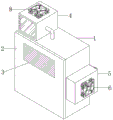
Fig. 1 is a schematic front perspective view of an intelligent digital program-controlled dispatching device according to the present invention;
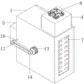
fig. 2 is a schematic diagram of a back side three-dimensional structure of the intelligent digital program-controlled dispatching device provided by the utility model;
fig. 3 is a schematic perspective view of a part of the intelligent digital program-controlled scheduling device according to the present invention in a hidden state;
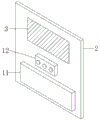
fig. 4 is a schematic back perspective view of a disassembly plate in the intelligent digital program-controlled scheduling device according to the present invention.
In the figure: the device comprises a shell 1, a detachable plate 2, an operation screen 3, a dust removal box 4, an air supply hood 5, a heat dissipation fan 6, a heat dissipation grid 7, an air extraction fan 8, a filter screen 9, a dust extraction hood 10, an electrode plate 11, an electrostatic generator 12, a motor 13, a driving belt pulley 14, an air supply outlet 15, a rotating shaft 16, a driven belt pulley 17 and an air deflector 18.
Detailed Description
The technical solutions in the embodiments of the present invention will be clearly and completely described below with reference to the drawings in the embodiments of the present invention, and it is obvious that the described embodiments are only a part of the embodiments of the present invention, and not all of the embodiments.
Referring to fig. 1-4, the intelligent digital program-controlled scheduling device comprises a shell 1, a dismounting plate 2, an operation screen 3, a dust removal box 4, an air supply hood 5, a heat dissipation mechanism and a dust removal mechanism, wherein the dismounting plate 2 is installed on the outer wall of the front side of the shell 1 through bolts, the operation screen 3 is fixed on the dismounting plate 2, the dust removal box 4 is welded on the outer wall of the top of the shell 1, the air supply hood 5 is fixed on the outer wall of one side of the shell 1, and the heat dissipation mechanism and the dust removal mechanism are sequentially arranged on the shell 1;
the heat dissipation mechanism comprises a heat dissipation fan 6, a heat dissipation grid 7 and an air direction adjusting component, the heat dissipation fan 6 is fixedly communicated with the side wall of the air supply hood 5 through bolts, the heat dissipation grid 7 is fixedly communicated with the inner wall of the other side of the shell 1, the air direction adjusting component comprises a motor 13, a driving belt pulley 14, an air supply opening 15, a rotating shaft 16, a driven belt pulley 17 and an air deflector 18, the motor 13 is fixedly arranged on the central outer wall of the back of the shell 1 through bolts, the driving belt pulley 14 is sleeved on an output shaft of the motor 13, the air supply opening 15 is arranged on the inner wall of one side of the shell 1, the rotating shaft 16 is respectively connected with the inner walls of the two sides of the air supply opening 15 through two bearings, the driven belt pulley 17 and the air deflector 18 are sequentially sleeved on the rotating shaft 16, the driving belt pulley 14 and the driven belt pulley 17 are connected through belt transmission, the air deflector 18 is provided with evenly distributed air guide holes, the air deflector 18 is positioned in the air supply opening 15, the mounting opening is formed in the inner wall of the other side of the shell 1, the heat dissipation grating 7 is fixed on the peripheral inner wall of the mounting opening through bolts, and the heat dissipation mechanism is arranged, so that the wind direction of cold wind blown by the heat dissipation fan 6 can be continuously adjusted through the wind direction adjusting assembly, the heat dissipation range is improved, the heat dissipation is more uniform, the working efficiency of the device is improved, and the service life of the device is prolonged;
the dust removal mechanism comprises an air exhaust fan 8, a filter screen 9, a dust exhaust cover 10 and an electrostatic dust removal component, wherein the air exhaust fan 8 is fixedly communicated with the outer wall of the top of the dust exhaust box 4 through bolts, the filter screen 9 is fixedly arranged on the inner wall of one side of the dust exhaust box 4 through bolts, the dust exhaust cover 10 is arranged in the shell 1, the dust exhaust cover 10 is fixedly communicated with the inner wall of one side of the dust exhaust box 4 through an exhaust pipe arranged below the filter screen 9, the front surface of the dust exhaust box 4 is hinged with a sealing door, the electrostatic dust removal component comprises a plate electrode 11 and an electrostatic generator 12 which are sequentially fixed on the outer wall of the back surface of the dismounting plate 2 through bolts, the output end of the electrostatic generator 12 is electrically connected with the input end of the plate electrode 11, the dust removal mechanism is arranged, most of dust in the shell 1 is exhausted to the dust exhaust box 4 from the dust exhaust cover 10 through the air exhaust fan 8, and the dust is collected in the dust exhaust box 4 through interception under the filter screen 9, and through the electrostatic precipitator subassembly, under the effect of electrostatic generator 12, electrode plate 11 produces the effect of electrostatic absorption, conveniently carries out the secondary with some dust that are not absorbed and adsorbs, and then can improve the dust removal effect and the quality of whole dust removal mechanism to can reduce the device inside and adhere to the harmful effects that a large amount of dust led to the fact to electrical components to a certain extent.
The working principle is as follows: when heat dissipation is carried out, the cooling fan 6 conveys cold air into the shell 1 from the air supply opening 15, heat in the shell 1 is quickly discharged to the outside from the heat dissipation grille 7, meanwhile, the driving belt pulley 14 is driven to rotate by the motor 13, the driven belt pulley 17 drives the rotating shaft 16 to rotate under the transmission action of the belt, then the rotating shaft 16 drives the air deflector 18 to rotate so as to continuously adjust the wind direction of the cold air blown by the cooling fan 6, when dust removal is carried out, most of dust in the shell 1 is pumped into the dust removal box 4 from the dust extraction cover 10 by the air exhaust fan 8, the dust is collected in the dust removal box 4 under the interception of the filter screen 9, under the action of the electrostatic generator 12, the electrode plate 11 generates an electrostatic adsorption effect, secondary adsorption of some dust which is not sucked away is convenient, and the dust collected at the bottom of the dust removal box 4 is conveniently cleaned regularly by regularly opening the sealing door, maintenance is facilitated by periodically removing the removal plate 2 and dust adsorbed on the surface of the electrode plate 11 is periodically cleaned.
In the description of the present invention, it is to be understood that the terms "center", "longitudinal", "lateral", "length", "width", "thickness", "upper", "lower", "front", "rear", "left", "right", "vertical", "horizontal", "top", "bottom", "inner", "outer", "clockwise", "counterclockwise", and the like, indicate orientations and positional relationships based on those shown in the drawings, and are used only for convenience of description and simplicity of description, and do not indicate or imply that the equipment or element being referred to must have a particular orientation, be constructed and operated in a particular orientation, and thus, should not be considered as limiting the present invention.
Furthermore, the terms "first", "second" and "first" are used for descriptive purposes only and are not to be construed as indicating or implying relative importance or implicitly indicating the number of technical features indicated. Thus, a feature defined as "first" or "second" may explicitly or implicitly include one or more of that feature. In the description of the present invention, "a plurality" means two or more unless specifically defined otherwise.
The above description is only for the preferred embodiment of the present invention, but the scope of the present invention is not limited thereto, and any person skilled in the art should be considered to be within the technical scope of the present invention, and equivalent alternatives or modifications according to the technical solution of the present invention and the inventive concept thereof should be covered by the scope of the present invention.
Claims (7)
1. An intelligent digital program-controlled scheduling device comprises a shell (1) with a disassembly plate (2) arranged on the outer wall of the front side through a bolt, an operation screen (3) is fixed on the disassembly plate (2), it is characterized in that the outer wall of the top of the shell (1) is welded with a dust removing box (4), an air supply cover (5) is fixed on the outer wall of one side of the shell (1), a heat dissipation mechanism and a dust removal mechanism are sequentially arranged on the shell (1), the heat dissipation mechanism comprises a heat dissipation fan (6) fixedly communicated with the side wall of the air supply cover (5) through bolts, a heat dissipation grid (7) fixedly communicated with the inner wall of the other side of the shell (1) and an air direction adjusting component, the dust removal mechanism comprises an air exhaust fan (8) fixedly communicated with the outer wall of the top of the dust removal box (4) through bolts, a filter screen (9) fixedly communicated with the inner wall of one side of the dust removal box (4) through bolts, a dust extraction cover (10) positioned in the shell (1) and an electrostatic dust removal assembly.
2. The intelligent digital program-controlled scheduling device of claim 1, wherein the electrostatic dust removal assembly comprises an electrode plate (11) and an electrostatic generator (12) which are sequentially fixed on the outer wall of the back surface of the detachable plate (2) through bolts, and the output end of the electrostatic generator (12) is electrically connected with the input end of the electrode plate (11).
3. The intelligent digital program-controlled scheduling device of claim 1, wherein the wind direction adjusting assembly comprises a motor (13) fixed on the outer wall of the center of the back of the casing (1) through a bolt, a driving belt pulley (14) sleeved on the output shaft of the motor (13), an air supply outlet (15) arranged on the inner wall of one side of the casing (1), a rotating shaft (16), and a driven belt pulley (17) and an air deflector (18) sleeved on the rotating shaft (16) in sequence.
4. The intelligent digital program-controlled dispatching device according to claim 3, wherein the driving pulley (14) is in transmission connection with the driven pulley (17) through a belt, and the air deflector (18) is provided with air guide holes which are uniformly distributed at equal intervals.
5. The intelligent digital program-controlled dispatching device according to claim 3, wherein the rotating shaft (16) is connected with the inner walls of the two sides of the air supply opening (15) through two bearings, and the air deflector (18) is positioned in the air supply opening (15).
6. The intelligent digital program-controlled scheduling device of claim 1, wherein the inner wall of one side of the dust removal box (4) is fixedly communicated with the dust hood (10) through an exhaust pipe positioned below the filter screen (9), and the front surface of the dust removal box (4) is hinged with a sealing door.
7. The intelligent digital program-controlled scheduling device of claim 1, wherein the inner wall of the other side of the casing (1) is provided with a mounting opening, and the heat dissipation grating (7) is fixed on the inner wall of the periphery of the mounting opening through bolts.
Priority Applications (1)
| Application Number | Priority Date | Filing Date | Title |
|---|---|---|---|
| CN202121841327.3U CN215500248U (en) | 2021-08-09 | 2021-08-09 | Intelligent digital program-controlled dispatching device |
Applications Claiming Priority (1)
| Application Number | Priority Date | Filing Date | Title |
|---|---|---|---|
| CN202121841327.3U CN215500248U (en) | 2021-08-09 | 2021-08-09 | Intelligent digital program-controlled dispatching device |
Publications (1)
| Publication Number | Publication Date |
|---|---|
| CN215500248U true CN215500248U (en) | 2022-01-11 |
Family
ID=79757006
Family Applications (1)
| Application Number | Title | Priority Date | Filing Date |
|---|---|---|---|
| CN202121841327.3U Active CN215500248U (en) | 2021-08-09 | 2021-08-09 | Intelligent digital program-controlled dispatching device |
Country Status (1)
| Country | Link |
|---|---|
| CN (1) | CN215500248U (en) |
-
2021
- 2021-08-09 CN CN202121841327.3U patent/CN215500248U/en active Active
Similar Documents
| Publication | Publication Date | Title |
|---|---|---|
| CN211017985U (en) | Distribution box for electric automation | |
| CN115579756B (en) | Energy-efficient low-voltage distribution cabinet | |
| CN111542208A (en) | Circulating air-draft type dust removal and heat dissipation device for electromechanical equipment | |
| CN210182889U (en) | Ring main unit heat abstractor | |
| CN215500248U (en) | Intelligent digital program-controlled dispatching device | |
| CN212783589U (en) | Heat abstractor for new energy battery | |
| CN112670868A (en) | Electric power cabinet with dustproof heat dissipation function | |
| CN215217257U (en) | Water turbine cooling tower with sand prevention function | |
| CN211529107U (en) | Computer heat abstractor | |
| CN212753667U (en) | Novel livestock-raising ventilation device | |
| CN214314150U (en) | Centrally installed switchgear monitoring device for power distribution | |
| CN208190454U (en) | A kind of good motor of heat dissipation effect | |
| CN209057019U (en) | A kind of automotive alternator protective cover | |
| CN113641620A (en) | Server protector for big data based on computer | |
| CN210799126U (en) | Engine radiator | |
| CN220122704U (en) | Energy-saving motor | |
| CN112533423A (en) | Computer network equipment box convenient to move | |
| CN214499498U (en) | Efficient energy saving and consumption reduction device of blower motor of thermal power plant | |
| CN218451983U (en) | Energy-concerving and environment-protective type circulation dust removal electrical equipment | |
| CN220042666U (en) | Photovoltaic special box transformer cabinet | |
| CN218109636U (en) | Electric welding machine shell with good heat dissipation performance | |
| CN216210045U (en) | Heat radiation structure for optical fiber adapter | |
| CN214625168U (en) | Battery constant temperature protection architecture for electric motor car | |
| CN217403194U (en) | Energy regeneration type water circulation cooling device of cooling tower | |
| CN219678409U (en) | Photovoltaic junction box with heat radiation structure |
Legal Events
| Date | Code | Title | Description |
|---|---|---|---|
| GR01 | Patent grant | ||
| GR01 | Patent grant |