CN215392866U - Cutting device of stainless steel square pipe - Google Patents
Cutting device of stainless steel square pipe Download PDFInfo
- Publication number
- CN215392866U CN215392866U CN202121008247.XU CN202121008247U CN215392866U CN 215392866 U CN215392866 U CN 215392866U CN 202121008247 U CN202121008247 U CN 202121008247U CN 215392866 U CN215392866 U CN 215392866U
- Authority
- CN
- China
- Prior art keywords
- gear
- support frame
- welded
- frame
- stainless steel
- Prior art date
- Legal status (The legal status is an assumption and is not a legal conclusion. Google has not performed a legal analysis and makes no representation as to the accuracy of the status listed.)
- Active
Links
Images
Landscapes
- Sawing (AREA)
Abstract
The utility model discloses a cutting device for a stainless steel square tube, which comprises a rectangular frame, wherein wheels are welded at four corners of the bottom end of the rectangular frame, a support frame is connected to the top end of the rectangular frame through bolts, a first speed reduction motor is connected to the top end of the right side of the support frame through bolts, a cross shaft is welded at the output end of the first speed reduction motor, penetrates through the outer wall of the support frame and is welded with the output end of the first speed reduction motor, the left end of the cross shaft is connected with the support frame through a shaft, and the outer walls of the left end and the right end of the cross shaft are connected with fourth gears through a shaft. This cutting device of stainless steel side's pipe realizes the regulation of cutting motor position through structures such as rectangle frame, wheel, support frame, first gear motor, cross axle, fourth gear, fifth gear, threaded rod, diaphragm, realizes the centre gripping of side's pipe through structures such as connecting block, rectangular block, second gear motor, first gear, second gear, third gear, clamping jaw, bull stick, beneficial effect is obvious.
Description
Technical Field
The utility model relates to the technical field of stainless steel, in particular to a cutting device for a stainless steel square tube.
Background
The square pipe is the light-duty thin wall steel pipe in hollow square cross-section, also be called steel clod wash section bar, the usage of square pipe has the building, machine-building, projects such as steel construction, at current small-size side pipe cutting platform, cutting length generally measures for the operating personnel with the chi, operation error is big, and there is not guider on the current cutting platform, the condition that square pipe dropped can take place when placing square pipe, current cutting platform does not have square steel pipe clamping device, can not carry out the centre gripping to the steel pipe according to the thickness of square pipe, beneficial effect is not obvious, the adaptability is relatively poor.
SUMMERY OF THE UTILITY MODEL
The utility model aims to provide a cutting device for a stainless steel square tube, which aims to solve the problems in the background technology.
In order to achieve the purpose, the utility model provides the following technical scheme: the utility model provides a cutting device of stainless steel side pipe, includes the rectangle frame, the wheel has all been welded in the bottom four corners of rectangle frame, the top bolted connection of shape frame has the support frame, the right side top bolted connection of support frame has first gear motor, the outer wall welding that first gear motor's output runs through the support frame has the cross axle, the left end and the support frame looks coupling of cross axle, the outer wall all the coupling has the fourth gear about the cross axle, the bottom meshing of fourth gear has the fifth gear, the central point of fifth gear puts the bottom and has the threaded rod along the welding of upper and lower direction, the bottom and the support frame looks coupling of threaded rod, the outer wall spiro union of threaded rod has the diaphragm, the cutting motor is installed to the bottom of diaphragm, and fixture is all installed to the top left and right sides of rectangle frame.
Preferably, fixture includes connecting block, rectangular block, second gear, first gear, second gear, third gear, clamping jaw and bull stick, two from top to bottom the rectangular block has all been welded to the left end of clamping jaw, the rear side outer wall bottom side bolted connection of rectangular block has second gear, the output of second gear runs through the rectangular block and has welded first gear, the meshing of first gear right side outer wall has the second gear, the meshing of the top outer wall of second gear has the third gear, the bottom of second gear and the outside of third gear all weld with the clamping jaw mutually, the inboard hub connection of clamping jaw has the one end of bull stick, the other end hub connection of bull stick is at the front side outer wall of rectangular block, the connecting block is installed to the bottom of rectangular block, the rectangular block passes through connecting block and rectangular frame welding.
Preferably, the second gear and the third gear are the same in type.
Preferably, a rubber pad is pasted on the inner side of the clamping jaw.
Preferably, the cross section of the support frame is U-shaped.
Compared with the prior art, the utility model has the beneficial effects that: this cutting device of stainless steel side's pipe realizes the regulation of cutting motor position through structures such as rectangle frame, wheel, support frame, first gear motor, cross axle, fourth gear, fifth gear, threaded rod, diaphragm, realizes the centre gripping of side's pipe through structures such as connecting block, rectangular block, second gear motor, first gear, second gear, third gear, clamping jaw, bull stick, beneficial effect is obvious.
Drawings
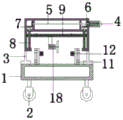
FIG. 1 is a front sectional view of a support plate structure according to the present invention;
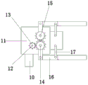
FIG. 2 is a left side view of the clamping mechanism of the present invention;
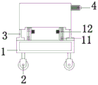
fig. 3 is a front view of the present invention.
In the figure: 1. rectangular frame, 2, wheel, 3, support frame, 4, first gear motor, 5, cross axle, 6, fourth gear, 7, fifth gear, 8, threaded rod, 9, diaphragm, 10, connecting block, 11, rectangular block, 12, second gear motor, 13, first gear, 14, second gear, 15, third gear, 16, clamping jaw, 17, bull stick, 18, cutting motor.
Detailed Description
The technical solutions in the embodiments of the present invention will be clearly and completely described below with reference to the drawings in the embodiments of the present invention, and it is obvious that the described embodiments are only a part of the embodiments of the present invention, and not all of the embodiments. All other embodiments, which can be derived by a person skilled in the art from the embodiments given herein without making any creative effort, shall fall within the protection scope of the present invention.
Referring to fig. 1-3, the present invention provides a technical solution: a cutting device for stainless steel square pipes comprises a rectangular frame 1, wherein the rectangular frame 1 plays a supporting role, wheels 2 are welded at four corners of the bottom end of the rectangular frame 1, the wheels 2 are convenient to move, a supporting frame 3 is connected to the top end of the rectangular frame 1 through bolts, the supporting frame 3 plays a supporting role for internal structures, a first speed reducing motor 4 is connected to the top end of the right side of the supporting frame 3 through bolts, the output end of the first speed reducing motor 4 penetrates through the outer wall of the supporting frame 3 and is welded with a cross shaft 5, the first speed reducing motor 4 drives the cross shaft 5 to rotate clockwise, the left end of the cross shaft 5 is connected with the supporting frame 3 in a shaft mode, the outer walls of the left end and the right end of the cross shaft 5 are connected with a fourth gear 6 in a shaft mode, the cross shaft 5 drives the fourth gear 6 to rotate clockwise, a fifth gear 7 is meshed at the bottom end of the fourth gear 6, the fourth gear 6 drives the fifth gear 7 to rotate anticlockwise, a threaded rod 8 is welded at the bottom end of the central position of the fifth gear 7 in the up-down direction, the fifth gear 7 drives the threaded rod 8 to rotate anticlockwise, the bottom end of the threaded rod 8 is in shaft connection with the support frame 3, the outer wall of the threaded rod 8 is in threaded connection with the transverse plate 9, the cutting motor 18 is installed at the bottom end of the transverse plate 9, the threaded rod 8 rotates anticlockwise to enable the cutting motor 18 to move downwards to a proper position through the transverse plate 9, and the clamping mechanisms are installed on the left side and the right side of the top end of the rectangular frame 1.
As a preferable scheme, the clamping mechanism comprises a connecting block 10, a rectangular block 11, a second speed reducing motor 12, a first gear 13, a second gear 14, a third gear 15, clamping jaws 16 and a rotating rod 17, the rectangular block 11 is welded at the left ends of the upper clamping jaw 16 and the lower clamping jaw 16, the rectangular block 11 plays a supporting role, the second speed reducing motor 12 is connected with the outer side of the bottom end of the outer wall of the rear side of the rectangular block 11 through a bolt, the first gear 13 is welded at the output end of the second speed reducing motor 12 through the rectangular block 11, the second speed reducing motor 12 rotates clockwise to drive the first gear 13 to rotate clockwise, the second gear 14 is meshed with the outer wall of the right side of the first gear 13, the first gear 13 drives the second gear 14 to rotate anticlockwise, the third gear 15 is meshed with the outer wall of the top end of the second gear 14, the second gear 14 drives the third gear 15 to rotate clockwise, the bottom end of the second gear 14 and the outer side of the third gear 15 are welded with the clamping jaws 16, the clamping jaw 16 moves inwards to clamp the square tube, the inner side of the clamping jaw 16 is connected with one end of a rotating rod 17 in a shaft mode, the other end of the rotating rod 17 is connected to the outer wall of the front side of the rectangular block 11 in a shaft mode, the rotating rod 17 limits the movement of the clamping jaw 16, the connecting block 10 is installed at the bottom end of the rectangular block 11, and the rectangular block 11 is welded with the rectangular frame 1 through the connecting block 10.
Preferably, the second gear 14 and the third gear 15 are the same in type, and the second gear 14 drives the third gear 15 to rotate clockwise.
Preferably, a rubber pad is adhered to the inside of the jaw 16, and the rubber pad plays a role of anti-slip.
As preferred scheme, the cross section of support frame 3 is "U" style of calligraphy, and support frame 3 plays the supporting role.
The detailed connection means is a technique known in the art, and the following mainly describes the working principle and process, and the specific operation is as follows.
When the square tube cutting machine is used, firstly, the equipment is connected with an external power supply, the first speed reduction motor 4 is enabled to rotate clockwise, the first speed reduction motor 4 drives the transverse shaft 5 to rotate clockwise, the transverse shaft 5 drives the first gear 6 to rotate clockwise, the fourth gear 6 drives the fifth gear 7 to rotate anticlockwise, the fifth gear 7 drives the threaded rod 8 to rotate anticlockwise, the threaded rod 8 rotates anticlockwise to enable the cutting motor 18 to move downwards to a proper position through the transverse plate 9, the first speed reduction motor 4 is stopped, the second speed reduction motor 12 is powered on at the moment, the second speed reduction motor 12 rotates clockwise to drive the first gear 13 to rotate clockwise, the first gear 13 drives the second gear 14 to rotate anticlockwise, the second gear 14 drives the third gear 15 to rotate clockwise, the clamping jaw 16 moves inwards to clamp the square tube, the square tube is wide in design application range and obvious in beneficial effect, and the square tube cutting machine is beneficial to popularize and use.
In the description of the present invention, it is to be understood that the terms "coaxial", "bottom", "one end", "top", "middle", "other end", "upper", "one side", "top", "inner", "front", "center", "two ends", and the like, indicate orientations or positional relationships based on those shown in the drawings, and are used only for convenience in describing the present invention and for simplicity in description, and do not indicate or imply that the referenced devices or elements must have a particular orientation, be constructed in a particular orientation, and be operated; also, unless expressly stated or limited otherwise, the terms "snap" and "pivot" and "snap" and "weld" and "screw" are to be construed broadly, e.g., as a fixed connection, a removable connection, or an integral part; can be mechanically or electrically connected; the terms may be directly connected or indirectly connected through an intermediate, and may be communication between two elements or interaction relationship between two elements, unless otherwise specifically limited, and the specific meaning of the terms in the present invention will be understood by those skilled in the art according to specific situations.
Although embodiments of the present invention have been shown and described, it will be appreciated by those skilled in the art that changes, modifications, substitutions and alterations can be made in these embodiments without departing from the principles and spirit of the utility model, the scope of which is defined in the appended claims and their equivalents.
Claims (5)
1. The utility model provides a cutting device of stainless steel side pipe, includes rectangle frame (1), its characterized in that: the cutting machine is characterized in that wheels (2) are welded at four corners of the bottom of the rectangular frame (1), a support frame (3) is connected to the top of the rectangular frame (1) through bolts, a first speed reduction motor (4) is connected to the top of the right side of the support frame (3) through bolts, a cross shaft (5) is welded at the outer wall of the output end of the first speed reduction motor (4) penetrating through the support frame (3), the left end of the cross shaft (5) is in shaft joint with the support frame (3), a fourth gear (6) is in shaft joint with the outer walls of the left end and the right end of the cross shaft (5), a fifth gear (7) is meshed at the bottom end of the fourth gear (6), a threaded rod (8) is welded at the bottom end of the central position of the fifth gear (7) along the vertical direction, the bottom end of the threaded rod (8) is in shaft joint with the support frame (3), a transverse plate (9) is in screw joint with the outer wall of the threaded rod (8), and a cutting motor (18) is installed at the bottom end of the transverse plate (9), clamping mechanisms are arranged on the left side and the right side of the top end of the rectangular frame (1).
2. The cutting device of stainless steel square tubes according to claim 1, wherein: the clamping mechanism comprises a connecting block (10), a rectangular block (11), a second speed reducing motor (12), a first gear (13), a second gear (14), a third gear (15), clamping jaws (16) and a rotating rod (17), wherein the rectangular block (11) is welded at the left end of each of the clamping jaws (16) up and down, the second speed reducing motor (12) is connected to the outer side of the bottom end of the outer wall of the rear side of the rectangular block (11) through bolts, the first gear (13) is welded at the output end of the second speed reducing motor (12) after penetrating through the rectangular block (11), the second gear (14) is meshed with the outer wall of the right side of the first gear (13), the third gear (15) is meshed with the outer wall of the top end of the second gear (14), the bottom end of the second gear (14) and the outer side of the third gear (15) are welded with the clamping jaws (16), and one end of the rotating rod (17) is axially connected to the inner side of the clamping jaws (16), the other end of bull stick (17) is the hub connection at the front side outer wall of rectangle piece (11), connecting block (10) are installed to the bottom of rectangle piece (11), rectangle piece (11) are through connecting block (10) and rectangle frame (1) welding.
3. The cutting device of stainless steel square tubes according to claim 2, wherein: the second gear (14) and the third gear (15) are the same in type.
4. The cutting device of stainless steel square tubes according to claim 2, wherein: and a rubber pad is stuck to the inner side of the clamping jaw (16).
5. The cutting device of stainless steel square tubes according to claim 1, wherein: the cross section of the support frame (3) is U-shaped.
Priority Applications (1)
| Application Number | Priority Date | Filing Date | Title |
|---|---|---|---|
| CN202121008247.XU CN215392866U (en) | 2021-05-12 | 2021-05-12 | Cutting device of stainless steel square pipe |
Applications Claiming Priority (1)
| Application Number | Priority Date | Filing Date | Title |
|---|---|---|---|
| CN202121008247.XU CN215392866U (en) | 2021-05-12 | 2021-05-12 | Cutting device of stainless steel square pipe |
Publications (1)
| Publication Number | Publication Date |
|---|---|
| CN215392866U true CN215392866U (en) | 2022-01-04 |
Family
ID=79674980
Family Applications (1)
| Application Number | Title | Priority Date | Filing Date |
|---|---|---|---|
| CN202121008247.XU Active CN215392866U (en) | 2021-05-12 | 2021-05-12 | Cutting device of stainless steel square pipe |
Country Status (1)
| Country | Link |
|---|---|
| CN (1) | CN215392866U (en) |
-
2021
- 2021-05-12 CN CN202121008247.XU patent/CN215392866U/en active Active
Similar Documents
| Publication | Publication Date | Title |
|---|---|---|
| CN210703411U (en) | Major diameter circular steel pipe butt joint timing device | |
| CN215392866U (en) | Cutting device of stainless steel square pipe | |
| CN105921916B (en) | A kind of seam welder draw-gear | |
| CN202928970U (en) | Flaw detection car for industrial X ray | |
| CN104874903A (en) | Self-travelling type submerged-arc welding trolley | |
| CN211848665U (en) | High-efficient track laying device for railway transportation | |
| CN217913777U (en) | Auxiliary mechanism for welding device | |
| CN210414434U (en) | Movable bracket for passenger car engine | |
| CN210649203U (en) | Adjustable welding part fixing device | |
| CN214816058U (en) | Pipe fitting welding set | |
| CN213497420U (en) | Trailer bottom plate welding position device | |
| CN215824707U (en) | High efficiency planer-type tubular product welding machine | |
| CN216607495U (en) | Pure titanium cutting machine | |
| CN220092614U (en) | Round tube straightening machine capable of synchronously working inside and outside | |
| CN216235934U (en) | Lifting system for water purification equipment maintenance device | |
| CN219666386U (en) | Clamping equipment for driving axle machining | |
| CN218908786U (en) | Connecting rod rises to break and confirms and carries slip table | |
| CN202079348U (en) | Plasma bevel cutting device based on four-rod mechanism and cutting torch expansion | |
| CN213534752U (en) | Portable handcart installation base | |
| CN115533434B (en) | Clamping device for machining box body beam | |
| CN217600112U (en) | A movable winding device for water conservancy pipeline is laid | |
| CN216656985U (en) | Supporting and fixing structure for welding natural gas pipeline | |
| CN215443241U (en) | Building reinforcing apparatus suitable for wall body is restoreed | |
| CN220445526U (en) | Welding set is used in pump station construction | |
| CN215323516U (en) | Tubular workpiece boxing device |
Legal Events
| Date | Code | Title | Description |
|---|---|---|---|
| GR01 | Patent grant | ||
| GR01 | Patent grant | ||
| EE01 | Entry into force of recordation of patent licensing contract |
Assignee: SHENYANG DEXINLONG CNC MACHINE TOOL Co.,Ltd. Assignor: SHENYANG RENXING MACHINERY MANUFACTURING Co.,Ltd. Contract record no.: X2023210000109 Denomination of utility model: A Cutting Device for Stainless Steel Square Tube Granted publication date: 20220104 License type: Common License Record date: 20230908 |
|
| EE01 | Entry into force of recordation of patent licensing contract |