CN215376069U - Adjustable projection screen supporting pad structure - Google Patents
Adjustable projection screen supporting pad structure Download PDFInfo
- Publication number
- CN215376069U CN215376069U CN202120985696.3U CN202120985696U CN215376069U CN 215376069 U CN215376069 U CN 215376069U CN 202120985696 U CN202120985696 U CN 202120985696U CN 215376069 U CN215376069 U CN 215376069U
- Authority
- CN
- China
- Prior art keywords
- groove
- support
- fixing
- block
- adjusting
- Prior art date
- Legal status (The legal status is an assumption and is not a legal conclusion. Google has not performed a legal analysis and makes no representation as to the accuracy of the status listed.)
- Active
Links
Images


Landscapes
- Overhead Projectors And Projection Screens (AREA)
Abstract
The utility model discloses an adjustable projection screen supporting pad structure, which comprises an upper screen fixing bolt, an upper supporting fixing block, a fixing ring, a supporting and adjusting bearing, an adjusting wheel sealing ring, a supporting and adjusting universal wheel, a base fixing mechanism, an adjusting screw rod reinforcing mechanism and a horizontal adjusting screw rod, wherein the outer surface of the lower end of the upper screen fixing bolt is provided with the upper supporting fixing block, the outer surfaces of the periphery of the upper supporting fixing block are provided with the fixing ring, the outer surface of the lower end of the fixing ring is provided with the supporting and adjusting bearing, a positioning clamping block can be retracted into an installation shaft under pressure when the adjustment is needed through the arranged base fixing mechanism, and the clamping block can be popped out due to an elastic piece in the installation shaft after the clamping groove in the universal wheel is adjusted, so that the clamping is carried out, and the deviation of the adjusted angle is avoided, bringing better use prospect.
Description
Technical Field
The utility model relates to the technical field of projection screen support pads, in particular to an adjustable projection screen support pad structure.
Background
The projection screen support pad is a support structure provided for the projection screen.
The existing supporting pad for the projection screen has the following two problems:
1. the existing projection screen supporting pad cannot effectively fix the projection screen supporting pad after the angle is adjusted, so that the adjusted angle is easy to deviate, and certain inconvenience is caused.
2. The existing supporting pad for the projection screen has the advantages that the horizontal bar adjusting screw rod is easy to loosen and fall off after being fixed for a long time, and the horizontal degree can not be effectively maintained.
The adjustable projection screen support pad structure brings certain adverse effects to the using process of people, and aims to overcome the defects, the adjustable projection screen support pad structure is provided.
SUMMERY OF THE UTILITY MODEL
Technical problem to be solved
Aiming at the defects of the prior art, the utility model provides an adjustable projection screen support pad structure, which has the advantages of 11 and the like and can effectively solve the problems in the background technology.
(II) technical scheme
In order to achieve the purpose, the utility model adopts the technical scheme that: the utility model provides an adjustable projection screen supporting pad structure, includes screen fixing bolt, goes up support fixed block, solid fixed ring, supports adjustment bearing, adjustment wheel sealing washer, supports adjustment universal wheel, base fixed establishment, adjustment screw rod strengthening mechanism, horizontal adjustment screw rod, its characterized in that: go up screen fixing bolt's lower extreme surface and be provided with the support fixed block, the surface all around of going up the support fixed block is provided with solid fixed ring, gu fixed ring's lower extreme surface is provided with the support adjustment bearing.
Preferably, a connecting groove is arranged between the upper supporting and fixing block and the upper screen fixing bolt, the upper supporting and fixing block is detachably connected with the outer surface of the lower end of the upper screen fixing bolt through the connecting groove, a connecting piece is arranged between the fixing ring and the upper supporting and fixing block, the fixing ring is detachably connected with the outer surface of the periphery of the upper supporting and fixing block through the connecting piece, a connecting shaft is arranged between the supporting and adjusting bearing and the fixing ring, the supporting and adjusting bearing is movably connected with the outer surface of the lower end of the fixing ring through the connecting shaft, a connecting piece is arranged between the adjusting wheel sealing ring and the supporting and adjusting bearing, the adjusting wheel sealing ring is movably connected with the outer surface of the lower end of the supporting and adjusting bearing through the connecting piece, a connecting piece is arranged between the supporting and adjusting universal wheel and the adjusting wheel sealing ring, the supporting and adjusting universal wheel is detachably connected with the outer surface of the lower end of the adjusting wheel sealing ring through the connecting piece, the base fixed establishment with support and adjust and be provided with the spread groove between the universal wheel, base fixed establishment passes through the spread groove and can dismantle with the lower extreme surface that supports the adjustment universal wheel and be connected, be provided with the cell body between horizontal adjustment screw rod and the base fixed establishment, horizontal adjustment screw rod passes through the cell body and can dismantle with base fixed establishment's lower extreme surface and be connected, adjustment screw rod strengthening mechanism and horizontal adjustment screw rod outer fixed surface all around be connected.
Preferably, the base fixing mechanism comprises a circular base, a locking hole, a threaded connector, an installation shaft and a limiting fixture block, wherein the locking hole and the threaded connector are located on the outer surface of the upper end of the circular base, the locking hole is located on the outer surface of the periphery of the threaded connector, the installation shaft is located on one side of the inner wall of the threaded connector, and the limiting fixture block is located on the outer surface of the periphery of the installation shaft.
Preferably, a groove is formed between the locking hole and the circular seat, the locking hole is fixedly connected with the outer surface of the upper end of the circular seat through the groove, a connecting piece is arranged between the threaded interface and the circular seat, the threaded interface is fixedly connected with the outer surface of the upper end of the circular seat through the connecting piece, a connecting piece is arranged between the mounting shaft and the threaded interface, the mounting shaft is fixedly connected with one side of the inner wall of the threaded interface through the connecting piece, an elastic piece is arranged between the limiting clamping block and the mounting shaft, and the limiting clamping block is movably connected with the outer surface of the periphery of the mounting shaft through the elastic piece.
Preferably, the adjusting screw reinforcing mechanism comprises a reinforcing nut, a gasket, a mounting groove and a clamping groove, the gasket is located on the outer surface of the upper end of the reinforcing nut, the mounting groove is located on one side of the inner wall of the reinforcing nut, and the clamping groove is located on the outer surface of the periphery of the reinforcing nut.
Preferably, be provided with the viscose between gasket and the reinforcement nut, the gasket passes through the viscose and is connected with reinforcement nut's upper end external fixed surface, be provided with the recess between mounting groove and the reinforcement nut, the mounting groove passes through recess and reinforcement nut's inner wall one side fixed connection, be provided with the recess between block groove and the reinforcement nut, the block groove passes through recess and reinforcement nut's external fixed surface all around and is connected.
(III) advantageous effects
Compared with the prior art, the utility model provides an adjustable projection screen supporting pad structure, which has the following beneficial effects:
1. this projection screen supporting pad, base fixed establishment through setting up, the installation axle of adoption is installed with supporting the adjustment universal wheel, installation axle spacing fixture block all around can be connected with the draw-in groove that supports the adjustment universal wheel inside after the installation, and spacing fixture block can receive the inside of pressure retraction installation axle when needs adjust, and the draw-in groove that corresponds the universal wheel inside adjusts the back fixture block and can pop out because of the elastic component of installation axle inside again, thereby carry out the chucking to it, avoid the angle after the adjustment to produce the deviation easily.
2. This projection screen supporting pad, through the adjusting screw reinforcing mechanism who sets up, the mounting groove of adoption is inside the helicine helicitic texture, cover around the horizontal adjusting screw after the installation of horizontal body adjusting screw, and utilize the mounting groove to install, and the upper end of reinforcement nut has a side gasket in addition, avoids reinforcing nut and base fixed establishment direct contact, also can use the tool to correspond the block groove and will reinforce the further locking of nut, thereby avoid the horizontal adjusting screw to appear pine taking off wind-guiding phenomenon in long-term mount.
Drawings
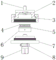
Fig. 1 is a schematic view of an overall structure of a support pad structure of an adjustable projection screen according to the present invention.
FIG. 2 is a structural view of a base fixing mechanism of a support pad structure of an adjustable projection screen according to the present invention.
FIG. 3 is a structural view of a reinforcing mechanism for adjusting screws of a support pad structure of an adjustable projection screen according to the present invention.
FIG. 4 is a schematic bottom view of an adjustable support pad structure for a projection screen according to the present invention.
In the figure: 1. fixing a bolt on the upper screen; 2. an upper supporting fixed block; 3. a fixing ring; 4. supporting the adjusting bearing; 5. a regulating wheel sealing ring; 6. supporting and adjusting universal wheels; 7. a base fixing mechanism; 8. adjusting the screw rod reinforcing mechanism; 9. a horizontal adjusting screw; 701. a circular seat; 702. a locking hole; 703. a threaded interface; 704. installing a shaft; 705. a limiting clamping block; 801. reinforcing the nut; 802. a gasket; 803. mounting grooves; 804. an engaging groove.
Detailed Description
In order to make the technical means, the creation characteristics, the achievement purposes and the effects of the utility model easy to understand, the utility model is further described with the specific embodiments.
In the description of the present invention, it should be noted that the terms "upper", "lower", "inner", "outer", "front", "rear", "both ends", "one end", "the other end", and the like indicate orientations or positional relationships based on those shown in the drawings, and are only for convenience of description and simplicity of description, but do not indicate or imply that the referred device or element must have a specific orientation, be constructed in a specific orientation, and be operated, and thus, should not be construed as limiting the present invention. Furthermore, the terms "first" and "second" are used for descriptive purposes only and are not to be construed as indicating or implying relative importance.
In the description of the present invention, it is to be noted that, unless otherwise explicitly specified or limited, the terms "mounted," "disposed," "connected," and the like are to be construed broadly, such as "connected," which may be fixedly connected, detachably connected, or integrally connected; can be mechanically or electrically connected; they may be connected directly or indirectly through intervening media, or they may be interconnected between two elements. The specific meanings of the above terms in the present invention can be understood in specific cases to those skilled in the art.
The first embodiment is as follows:
as shown in fig. 1-4, an adjustable projection screen supporting pad structure, includes screen fixing bolt 1, goes up support fixed block 2, solid fixed ring 3, support adjustment bearing 4, regulating wheel sealing washer 5, support adjustment universal wheel 6, base fixed establishment 7, adjusting screw reinforcing mechanism 8, horizontal adjustment screw 9, its characterized in that: an upper supporting and fixing block 2 is arranged on the outer surface of the lower end of an upper screen fixing bolt 1, fixing rings 3 are arranged on the outer surfaces of the periphery of the upper supporting and fixing block 2, a supporting and adjusting bearing 4 is arranged on the outer surface of the lower end of the fixing ring 3, a connecting groove is arranged between the upper supporting and fixing block 2 and the upper screen fixing bolt 1, the upper supporting and fixing block 2 is detachably connected with the outer surface of the lower end of the upper screen fixing bolt 1 through the connecting groove, a connecting piece is arranged between the fixing ring 3 and the upper supporting and fixing block 2, the fixing ring 3 is detachably connected with the outer surface of the periphery of the upper supporting and fixing block 2 through the connecting piece, a connecting shaft is arranged between the supporting and adjusting bearing 4 and the fixing ring 3, the supporting and adjusting bearing 4 is movably connected with the outer surface of the lower end of the fixing ring 3 through the connecting shaft, a connecting piece is arranged between the adjusting wheel sealing ring 5 and the supporting and adjusting bearing 4 through the connecting piece, support and be provided with the connecting piece between adjustment universal wheel 6 and the adjusting wheel sealing washer 5, support adjustment universal wheel 6 and can dismantle through the lower extreme surface of connecting piece and adjusting wheel sealing washer 5 and be connected, be provided with the spread groove between base fixed establishment 7 and the support adjustment universal wheel 6, base fixed establishment 7 can dismantle with the lower extreme surface that supports adjustment universal wheel 6 through the spread groove and be connected, be provided with the cell body between horizontal adjustment screw rod 9 and the base fixed establishment 7, horizontal adjustment screw rod 9 can dismantle through the lower extreme surface of cell body with base fixed establishment 7 and be connected, adjustment screw rod reinforcing mechanism 8 is connected with horizontal adjustment screw rod 9's surface fixed surface all around.
The second embodiment is as follows:
on the basis of the first embodiment, as shown in fig. 2, the base fixing mechanism 7 includes a circular seat 701, a locking hole 702, a threaded interface 703, a mounting shaft 704 and a limiting fixture block 705, the locking hole 702 and the threaded interface 703 are both located on the outer surface of the upper end of the circular seat 701, the locking hole 702 is located on the outer surface of the periphery of the threaded interface 703, the mounting shaft 704 is located on one side of the inner wall of the threaded interface 703, the limiting fixture block 705 is located on the outer surface of the periphery of the mounting shaft 704, a groove is formed between the locking hole 702 and the circular seat 701, the locking hole 702 is fixedly connected with the outer surface of the upper end of the circular seat 701 through the groove, a connecting member is arranged between the threaded interface 703 and the circular seat 701, the threaded interface 703 is fixedly connected with the outer surface of the upper end of the circular seat 701 through the connecting member, a connecting member is arranged between the mounting shaft 704 and the threaded interface 703, the mounting shaft 704 is fixedly connected with one side of the inner wall of the threaded interface 703 through the connecting member, an elastic part is arranged between the limiting clamping block 705 and the mounting shaft 704, and the limiting clamping block 705 is movably connected with the peripheral outer surface of the mounting shaft 704 through the elastic part, so that the limiting clamping block is clamped, and the problem that the adjusted angle is easy to deviate is avoided.
Example three:
on the basis of the first embodiment, as shown in fig. 3, the adjusting screw reinforcing mechanism 8 includes a reinforcing nut 801, a gasket 802, an installation groove 803, and a clamping groove 804, where the gasket 802 is located on an outer surface of an upper end of the reinforcing nut 801, the installation groove 803 is located on one side of an inner wall of the reinforcing nut 801, the clamping groove 804 is located on an outer surface of a periphery of the reinforcing nut 801, an adhesive is provided between the gasket 802 and the reinforcing nut 801, the gasket 802 is fixedly connected with the outer surface of the upper end of the reinforcing nut 801 through the adhesive, a groove is provided between the installation groove 803 and the reinforcing nut 801, the installation groove 803 is fixedly connected with one side of the inner wall of the reinforcing nut 801 through the groove, a groove is provided between the clamping groove 804 and the reinforcing nut 801, and the clamping groove 804 is fixedly connected with the outer surface of the periphery of the reinforcing nut 801 through the groove, thereby preventing the horizontal adjusting screw from loosening and guiding wind in the long-term fixing frame.
Principle of operation
The device comprises an upper screen fixing bolt 1, an upper supporting fixing block 2, a fixing ring 3, a supporting and adjusting bearing 4, an adjusting wheel sealing ring 5, a supporting and adjusting universal wheel 6, a base fixing mechanism 7, an adjusting screw reinforcing mechanism 8, a horizontal adjusting screw 9, a circular seat 701, a locking hole 702, a threaded interface 703, a mounting shaft 704, a limiting clamping block 705, a reinforcing nut 801, a gasket 802, a mounting groove 803, a clamping groove 804 and the like, wherein the mounting shaft and the supporting and adjusting universal wheel are mounted through the arranged base fixing mechanism, the limiting clamping block on the periphery of the mounting shaft is connected with the clamping groove in the supporting and adjusting universal wheel after mounting, the limiting clamping block can retract into the mounting shaft under pressure when adjustment is needed, and the clamping block can pop up due to an elastic piece in the mounting shaft after the clamping groove in the corresponding universal wheel is adjusted, so as to be clamped, avoid producing the deviation easily at the angle after the adjustment, through the adjusting screw reinforcing mechanism who sets up, the mounting groove inside of adoption is the helicine helicitic texture, the cover is around the horizontal adjusting screw after the installation of horizontal body adjusting screw, and utilize the mounting groove to install, and one side gasket in addition in the upper end of reinforcement nut, avoid reinforcement nut and base fixed establishment direct contact, also can use the instrument to correspond the further locking of block groove with the reinforcement nut, thereby avoid the horizontal adjusting screw to appear loosing and take off wind-guiding phenomenon at long-term mount.
It is noted that, herein, relational terms such as first and second (a, b, etc.) and the like may be used solely to distinguish one entity or action from another entity or action without necessarily requiring or implying any actual such relationship or order between such entities or actions. Also, the terms "comprises," "comprising," or any other variation thereof, are intended to cover a non-exclusive inclusion, such that a process, method, article, or apparatus that comprises a list of elements does not include only those elements but may include other elements not expressly listed or inherent to such process, method, article, or apparatus. Without further limitation, an element defined by the phrase "comprising an … …" does not exclude the presence of other identical elements in a process, method, article, or apparatus that comprises the element.
The foregoing shows and describes the general principles and broad features of the present invention and advantages thereof. It will be understood by those skilled in the art that the present invention is not limited to the embodiments described above, which are described in the specification and illustrated only to illustrate the principle of the present invention, but that various changes and modifications may be made therein without departing from the spirit and scope of the present invention, which fall within the scope of the utility model as claimed. The scope of the utility model is defined by the appended claims and equivalents thereof.
Claims (6)
1. The utility model provides an adjustable projection screen supporting pad structure, includes screen fixing bolt (1), goes up support fixed block (2), solid fixed ring (3), supports adjustment bearing (4), adjusting wheel sealing washer (5), supports adjustment universal wheel (6), base fixed establishment (7), adjusting screw reinforcing mechanism (8), horizontal adjustment screw rod (9), its characterized in that: go up the lower extreme surface of screen fixing bolt (1) and be provided with support fixed block (2), the surface all around of going up support fixed block (2) is provided with solid fixed ring (3), the lower extreme surface of solid fixed ring (3) is provided with supports adjustment bearing (4).
2. The adjustable projection screen support pad structure of claim 1, wherein: the screen support device is characterized in that a connecting groove is formed between the upper support fixing block (2) and the upper screen fixing bolt (1), the upper support fixing block (2) is detachably connected with the lower end outer surface of the upper screen fixing bolt (1) through the connecting groove, a connecting piece is arranged between the fixing ring (3) and the upper support fixing block (2), the fixing ring (3) is detachably connected with the peripheral outer surface of the upper support fixing block (2) through the connecting piece, a connecting shaft is arranged between the support adjusting bearing (4) and the fixing ring (3), the support adjusting bearing (4) is movably connected with the lower end outer surface of the fixing ring (3) through the connecting shaft, a connecting piece is arranged between the adjusting wheel sealing ring (5) and the support adjusting bearing (4), the adjusting wheel sealing ring (5) is movably connected with the lower end outer surface of the support adjusting bearing (4) through the connecting piece, support and be provided with the connecting piece between adjustment universal wheel (6) and adjustment wheel sealing washer (5), support adjustment universal wheel (6) and can dismantle through the lower extreme surface of connecting piece with adjustment wheel sealing washer (5) and be connected, base fixed establishment (7) and support are provided with the spread groove between adjustment universal wheel (6), base fixed establishment (7) can dismantle through the spread groove and the lower extreme surface that supports adjustment universal wheel (6) and be connected, be provided with the cell body between horizontal adjustment screw rod (9) and base fixed establishment (7), horizontal adjustment screw rod (9) can dismantle through the lower extreme surface of cell body with base fixed establishment (7) and be connected, adjustment screw rod strengthening mechanism (8) and horizontal adjustment screw rod (9) outer fixed connection all around.
3. The adjustable projection screen support pad structure of claim 1, wherein: the base fixing mechanism (7) comprises a circular base (701), a locking hole (702), a threaded interface (703), an installation shaft (704) and a limiting clamping block (705), wherein the locking hole (702) and the threaded interface (703) are both located on the outer surface of the upper end of the circular base (701), the locking hole (702) is located on the outer surface of the periphery of the threaded interface (703), the installation shaft (704) is located on one side of the inner wall of the threaded interface (703), and the limiting clamping block (705) is located on the outer surface of the periphery of the installation shaft (704).
4. The adjustable projection screen support pad structure of claim 3, wherein: the locking device is characterized in that a groove is formed between the locking hole (702) and the circular seat (701), the locking hole (702) is fixedly connected with the outer surface of the upper end of the circular seat (701) through the groove, a connecting piece is arranged between the threaded interface (703) and the circular seat (701), the threaded interface (703) is fixedly connected with the outer surface of the upper end of the circular seat (701) through the connecting piece, a connecting piece is arranged between the mounting shaft (704) and the threaded interface (703), the mounting shaft (704) is fixedly connected with one side of the inner wall of the threaded interface (703) through the connecting piece, an elastic piece is arranged between the limiting clamping block (705) and the mounting shaft (704), and the limiting clamping block (705) is movably connected with the outer surface of the periphery of the mounting shaft (704) through the elastic piece.
5. The adjustable projection screen support pad structure of claim 1, wherein: the adjusting screw reinforcing mechanism (8) comprises a reinforcing nut (801), a gasket (802), an installation groove (803) and a clamping groove (804), wherein the gasket (802) is located on the outer surface of the upper end of the reinforcing nut (801), the installation groove (803) is located on one side of the inner wall of the reinforcing nut (801), and the clamping groove (804) is located on the outer surface of the periphery of the reinforcing nut (801).
6. The adjustable projection screen support pad structure of claim 5, wherein: be provided with the viscose between gasket (802) and reinforced nut (801), upper end external surface fixed connection that gasket (802) passes through viscose and reinforced nut (801), be provided with the recess between mounting groove (803) and reinforced nut (801), inner wall one side fixed connection that mounting groove (803) pass through recess and reinforced nut (801), be provided with the recess between block groove (804) and reinforced nut (801), block groove (804) are through the recess and reinforced nut (801) external surface fixed connection all around.
Priority Applications (1)
| Application Number | Priority Date | Filing Date | Title |
|---|---|---|---|
| CN202120985696.3U CN215376069U (en) | 2021-05-10 | 2021-05-10 | Adjustable projection screen supporting pad structure |
Applications Claiming Priority (1)
| Application Number | Priority Date | Filing Date | Title |
|---|---|---|---|
| CN202120985696.3U CN215376069U (en) | 2021-05-10 | 2021-05-10 | Adjustable projection screen supporting pad structure |
Publications (1)
| Publication Number | Publication Date |
|---|---|
| CN215376069U true CN215376069U (en) | 2021-12-31 |
Family
ID=79629516
Family Applications (1)
| Application Number | Title | Priority Date | Filing Date |
|---|---|---|---|
| CN202120985696.3U Active CN215376069U (en) | 2021-05-10 | 2021-05-10 | Adjustable projection screen supporting pad structure |
Country Status (1)
| Country | Link |
|---|---|
| CN (1) | CN215376069U (en) |
-
2021
- 2021-05-10 CN CN202120985696.3U patent/CN215376069U/en active Active
Similar Documents
| Publication | Publication Date | Title |
|---|---|---|
| CN215376069U (en) | Adjustable projection screen supporting pad structure | |
| CN214923802U (en) | Adjustable locking and fixing device | |
| CN209692687U (en) | A kind of solar panel fixed frame | |
| CN210979269U (en) | Security protection system that conveniently adjusts is with control support | |
| CN210769623U (en) | Heavy oil hydraulic cylinder with double shafts having adjustable cap structures | |
| CN213366772U (en) | Antenna mounting bracket | |
| CN220955231U (en) | Door pocket installation connection structure | |
| CN213745878U (en) | Wireless electronic frequency modulation device | |
| CN221298708U (en) | Adjustable strutting arrangement of steel construction | |
| CN215057719U (en) | Cooling water pipe for water cooling system of new energy automobile engine | |
| CN211545040U (en) | Cotton core nib unloader | |
| CN221305810U (en) | Telescopic installation component for photovoltaic component and photovoltaic component installation structure | |
| CN212510194U (en) | Multi-angle mounting bracket for mechanical sensor | |
| CN219222877U (en) | Flat plate type solar collector mounting frame | |
| CN218819262U (en) | Camera assembly | |
| CN211070648U (en) | Diaphragm coating material throwing prevention structure | |
| CN216565011U (en) | Novel adjustable photovoltaic support | |
| CN215575421U (en) | Power equipment monitoring structure convenient to install | |
| CN221762460U (en) | Bearing frame convenient to fixed bearing | |
| CN213145938U (en) | Multi-station laser displacement sensor mounting and adjusting support for vehicle assembly | |
| CN210139213U (en) | High-strength aluminum alloy fixing seat | |
| CN221761077U (en) | Glass frame | |
| CN216243126U (en) | Encoder installing support | |
| CN214368895U (en) | Touch screen support device | |
| CN219623524U (en) | Building anti-seismic support |
Legal Events
| Date | Code | Title | Description |
|---|---|---|---|
| GR01 | Patent grant | ||
| GR01 | Patent grant |