CN215353636U - Waste collection and utilization device for refractory brick production - Google Patents
Waste collection and utilization device for refractory brick production Download PDFInfo
- Publication number
- CN215353636U CN215353636U CN202120950663.5U CN202120950663U CN215353636U CN 215353636 U CN215353636 U CN 215353636U CN 202120950663 U CN202120950663 U CN 202120950663U CN 215353636 U CN215353636 U CN 215353636U
- Authority
- CN
- China
- Prior art keywords
- fixed
- collecting box
- box
- crushing
- collecting
- Prior art date
- Legal status (The legal status is an assumption and is not a legal conclusion. Google has not performed a legal analysis and makes no representation as to the accuracy of the status listed.)
- Expired - Fee Related
Links
Images


Abstract
The utility model discloses a waste collecting and utilizing device for refractory brick production, and relates to the technical field of building material production. The dust collection box comprises a collection box, a partition plate is fixed inside the collection box, a dust collection cloth bag is arranged on the left side of the partition plate, a fan is fixed on the upper wall of the collection box corresponding to the position of the dust collection cloth bag, crushing rollers are symmetrically arranged on the upper portion of the right side of the partition plate, a crushing roller is arranged below the crushing rollers, a filter screen is arranged below the crushing rollers, a vibrator is fixed on the lower wall of the filter screen, a first motor and a second motor are respectively fixed on the rear wall of the collection box, and a plurality of support legs are fixed on the lower wall of the collection box. The utility model crushes the waste materials by the crushing roller and the crushing roller, continues to be put into production after being matched with the filtering of the filter screen, realizes that the waste materials can continue to be put into production after being processed, and carries out dust removal operation by the matching of the fan and the dust removal cloth bag, thereby avoiding the damage to the health of workers due to dust.
Description
Technical Field
The utility model belongs to the technical field of building material production, and particularly relates to a waste collection and utilization device for refractory brick production.
Background
The building material is various materials applied in the building engineering, wherein the firebrick is a refractory material fired by refractory clay or other refractory raw materials, is light yellow or brownish, is mainly used as a high-temperature building material and a structural material of a building kiln and various thermal equipment, can bear various physicochemical changes and mechanical actions at high temperature, and can be summarized as waste materials due to unqualified green brick size, cracks, distortion, edge deletion and corner dropping and other factors when the firebrick is produced, generally, the unqualified firebrick is collected and then used as a raw material and is crushed along with the raw material, but the firebrick still has the following defects in actual use:
1. the prior art does not have a device for specially collecting refractory brick waste, so that when a large amount of waste is used as raw materials, the raw materials of newly produced refractory bricks are not accurately proportioned, and the production yield of the refractory bricks is influenced;
2. the prior art has more dust when producing the refractory brick, which damages the health of workers.
Therefore, the prior art does not have the device of specially collecting the firebrick waste material, can lead to the ratio of the firebrick raw materials of new production not accurate when a large amount of waste materials act as the raw materials, still can influence the production output of firebrick, and the dust is more when prior art produces firebrick, harm staff's healthy, can't satisfy the demand in the in-service use, so urgent need can the modified technique on the market to solve above-mentioned problem.
SUMMERY OF THE UTILITY MODEL
The utility model aims to provide a waste collecting and utilizing device for refractory brick production, which is characterized in that waste is crushed by a crushing roller and a crushing roller, the crushed waste is continuously put into production after being filtered by a filter screen, and dust removal operation is carried out by the cooperation of a fan and a dust removal cloth bag, so that the problems that no device specially used for collecting refractory brick waste exists in the prior art, when a large amount of waste is used as a raw material, the proportioning of the newly produced refractory brick raw material is inaccurate, the production yield of refractory bricks is influenced, and when refractory bricks are produced by the prior art, more dust is generated, and the health of workers is damaged are solved.
In order to solve the technical problems, the utility model is realized by the following technical scheme:
the utility model relates to a waste collecting and utilizing device for refractory brick production, which comprises a collecting box, wherein a partition plate is fixed inside the collecting box, a dust removing cloth bag is arranged on the left side of the partition plate, a fan is fixed on the upper wall of the collecting box corresponding to the position of the dust removing cloth bag, crushing rollers are symmetrically arranged on the upper portion of the right side of the partition plate and rotate towards the direction of the adjacent crushing rollers, a crushing roller is arranged below the crushing rollers and rotates towards the direction of the adjacent crushing rollers, a filter screen is arranged below the crushing rollers, a vibrator is fixed on the lower wall of the filter screen, a first motor and a second motor are respectively fixed on the rear wall of the collecting box, a plurality of support legs are fixed on the lower wall of the collecting box, and the input ends of the first motor, the second motor, the vibrator and the fan are electrically connected with an external power supply through conducting wires.
Furthermore, the middle positions of the front end and the rear end of each crushing roller are respectively fixed with a first rotating rod, the first rotating rods are rotatably connected with the collecting box through first bearings, the peripheral walls of the crushing rollers are provided with crushing teeth, and the crushing teeth on the two crushing rollers are meshed and connected.
Further, the power output shaft of first motor is fixed mutually with arbitrary first dwang, the intermediate position department at both ends all is fixed with the second dwang around the crushing roller, and the second dwang passes through the second bearing and is connected with the collecting box rotation, the power output shaft of second motor is fixed mutually with the second dwang that corresponds.
Furthermore, a feeding box is fixed on the upper wall of the collecting box corresponding to the position between the two crushing rollers, the inside of the feeding box is communicated with the inside of the collecting box, the feeding box is positioned right above the position between the two crushing rollers, and a discharge hole is formed in the right side of the partition plate corresponding to the bottom of the collecting box.
Furthermore, springs are fixed at four corners of the lower wall of the filter screen, fixing plates are fixed at the bottoms of the springs and are respectively fixed on the side walls of the collecting box and the partition plate, the filter screen is arranged in a manner that the left side is high and the right side is low, an extending plate is fixed on the right wall of the filter screen, and the extending plate penetrates through the collecting box and extends to the outside of the collecting box.
Further, the left side of collecting box articulates there is the chamber door, the rear side of case door left side wall is fixed with the handle lock, the inside of dust removal sack is provided with the support frame, and the support frame fixes the upper surface in the inside of collecting box, the top of dust removal sack corresponds the upper wall of collecting box and has seted up the air vent, and the air vent is located the fan under.
Furthermore, an exhaust pipe is fixed on the outer portion of the fan and corresponds to the upper wall of the collection box, the exhaust pipe is L-shaped, an ash discharge port is formed in the lower portion of the dust removal cloth bag and corresponds to the bottom of the collection box, a baffle is inserted into the collection box corresponding to the ash discharge port, an air inlet pipe is arranged on the position of the dust removal cloth bag and corresponds to the rear wall of the collection box, and the inner portion of the air inlet pipe is communicated with the inner portion of the collection box corresponding to the left side of the partition plate.
The utility model has the following beneficial effects:
1. the utility model can be connected with the power supply of the first motor, the second motor and the vibrator by arranging the collecting box, the crushing roller, the vibrator, the filter sieve, the first motor and the second motor before throwing waste materials into the collecting box, when the first motor works, the crushing roller rotates towards the adjacent crushing roller, when the second motor works, the crushing roller rotates towards the adjacent crushing roller, and the vibrator drives the filter sieve to vibrate when working, at the moment, the waste materials are thrown into the material inlet box, the waste materials move downwards under the action of gravity and sequentially pass through the crushing roller and the crushing roller to fall onto the filter sieve, under the action of the vibrator, the waste materials which meet the required production specification pass through the filter sieve and pass through the material outlet to be discharged to the outside of the collecting box, and the waste materials which meet the required production specification slide along the upper wall of the filter sieve to the upper wall of the extending plate to be discharged to the outside of the collecting box, can drop into the inside of feeding box once more with the waste material that is not conform to the required specification of production this moment and carry out shredding again, until conforming to the required specification of production, compared with the prior art, the staff can drop into the inside of collecting box with the waste material temporarily and process the use of after crushing roller and crushing roller handle and cooperate the filter sieve again and make the waste material become the production material again, avoid because the not enough condition of the production output of the resistant firebrick of influence that leads to of the material of producing resistant firebrick takes place, it does not have the device of specially collecting resistant firebrick waste material to have solved prior art, the ratio that can lead to the resistant firebrick raw materials of new production is inaccurate when more quantity waste material acts as the raw materials, still can influence the problem of the production output of resistant firebrick.
2. According to the utility model, the fan and the dust removal cloth bag are arranged, one end of the air inlet pipe, which is far away from the collection box, can be placed beside a dust generation source before the device is used, after the power supply of the fan is started, dust is sucked into the collection box by airflow generated by the fan, and is intercepted in the collection box after being filtered by the dust removal cloth bag, so that the dust is prevented from flying around, and the problems that in the prior art, when refractory bricks are produced, more dust is generated, and the health of workers is damaged are solved.
Of course, it is not necessary for any product in which the utility model is practiced to achieve all of the above-described advantages at the same time.
Drawings
In order to more clearly illustrate the technical solutions of the embodiments of the present invention, the drawings used in the description of the embodiments will be briefly introduced below, and it is obvious that the drawings in the following description are only some embodiments of the present invention, and it is obvious for those skilled in the art that other drawings can be obtained according to the drawings without creative efforts.
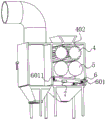
FIG. 1 is a cross-sectional structural view of the front side perspective of the present invention;
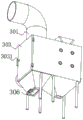
FIG. 2 is a left side perspective block diagram of the present invention;
FIG. 3 is a block diagram of the interior of the collection box of the present invention;
FIG. 4 is a bottom view of the present invention;
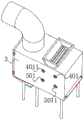
fig. 5 is a right side view structural diagram of the present invention.
In the drawings, the components represented by the respective reference numerals are listed below:
1. a fan; 2. a dust removal cloth bag; 3. a collection box; 301. an exhaust pipe; 302. a vent hole; 303. a box door; 3031. a handle lock; 304. a support frame; 305. an ash discharge port; 306. a baffle plate; 307. a partition plate; 308. a feeding box; 309. a discharge port; 310. a support leg; 311. an air inlet pipe; 4. a crushing roller; 401. a first rotating lever; 4011. a first bearing; 402. crushing teeth; 5. a crushing roller; 501. a second rotating lever; 5011. a second bearing; 6. filtering and screening; 601. a spring; 6011. a fixing plate; 602. an extension plate; 7. a vibrator; 8. a first motor; 9. a second motor.
Detailed Description
The technical solution in the embodiments of the present invention will be clearly and completely described below with reference to the accompanying drawings in the embodiments of the present invention.
Referring to fig. 1-5, the present invention relates to a waste collecting and utilizing device for refractory brick production, which comprises a collecting box 3, a partition plate 307 fixed inside the collecting box 3 can prevent dust from entering the right space of the partition plate 307 to pollute the waste, and simultaneously prevent the waste from entering the left space of the partition plate 307, a dust collecting bag 2 arranged at the left of the partition plate 307 can intercept the dust, the dust collecting bag 2 is positioned at a position corresponding to the upper wall of the collecting box 3 and can suck the dust into the left of the partition plate 307 corresponding to the inside of the collecting box 3 when a fan 1 fixed on the upper wall of the collecting box 2 works, crushing rollers 4 symmetrically arranged at the upper part of the right of the partition plate 307 can crush the waste to reduce the volume of the lump waste, so that the waste can pass through the space between two crushing rollers 5, and the crushing rollers 4 rotate towards the direction of the adjacent crushing rollers 4, and the crushing rollers 5 arranged below the crushing rollers 4 can crush the waste, the crushing rollers 5 rotate towards the direction of the adjacent crushing rollers 5, the filter sieve 6 arranged below the crushing rollers 5 can screen blocky waste materials, the materials which do not conform to the production specification are screened out and crushed again until the materials conform to the production specification, the filter sieve 6 can vibrate when the vibrator 7 fixed on the lower wall of the filter sieve 6 works, the crushing rollers 4 and the crushing rollers 5 can rotate when the first motor 8 and the second motor 9 respectively fixed on the rear wall of the collecting box 3 work, the plurality of support legs 310 fixed on the lower wall of the collecting box 3 are used for supporting the collecting box 3, the input ends of the first motor 8, the second motor 9, the vibrator 7 and the fan 1 are electrically connected with an external power supply through conductive wires, and the first motor 8 in the device, the second motor 9, the vibrator 7 and the fan 1 are all the prior art, and the model of the second motor is not limited herein.
Wherein as shown in fig. 1, 2, 3, 5, the intermediate position department at both ends all is fixed with first rotation pole 401 around the crushing roller 4, and first rotation pole 401 rotates with collecting box 3 through first bearing 4011 and is connected, broken tooth 402 has been seted up to the perisporium of crushing roller 4, and the meshing is connected between the broken tooth 402 on two crushing rollers 4, at first motor 8 during operation, the power output shaft of first motor 8 rotates and drives corresponding first rotation pole 401 and rotate, thereby make crushing roller 4 rotate, again because meshing is connected between the broken tooth 402 on two crushing rollers 4, when first motor 8 during operation, crushing roller 4 that first motor 8 drove can drive another crushing roller 4 and rotate, simultaneously because crushing roller 4 rotates to adjacent crushing roller 4 direction, realize carrying out kibbling purpose to the waste material.
The power output shaft of the first motor 8 is fixed with any one of the first rotating rods 401, the middle positions of the front end and the rear end of the crushing roller 5 are respectively fixed with a second rotating rod 501, the second rotating rods 501 are rotatably connected with the collecting box 3 through second bearings 5011, the power output shaft of the second motor 9 is fixed with the corresponding second rotating rods 501, when the second motor 9 works, the power output shaft of the second motor 9 rotates to drive the corresponding second rotating rods 501 to rotate, and because the crushing rollers 5 rotate towards the adjacent crushing rollers 5, the crushing rollers 5 can crush crushed waste materials under the working state of the second motor 9.
The upper wall that the position department corresponds collecting box 3 between two crushing roller 4 is fixed with feeding box 308, and the inside of feeding box 308 communicates with each other with the inside of collecting box 3, can move the waste material to the top of feeding box 308 when throwing the material and throw the material, feeding box 308 is located two crushing roller 4 directly over, the right-hand waste material that corresponds collecting box 3 that corresponds of baffle 307 has seted up discharge gate 309, the waste material that accords with the production standard after smashing is arranged to the outside of collecting box 3 by discharge gate 309.
The spring 601 fixed at the four corners of the lower wall of the filter sieve 6 enables the filter sieve 6 to vibrate when the vibrating machine 7 works, the fixing plate 6011 is fixed at the bottom of the spring 601, the fixing plate 6011 is fixed on the side walls of the collecting box 3 and the partition plate 307 respectively, the filter sieve 6 is arranged in a left-high mode, waste materials which are not in accordance with the production requirement specification can move rightwards to be discharged to the outside of the collecting box 3 conveniently, the extending plate 602 is fixed on the right wall of the filter sieve 6, and the extending plate 602 penetrates through the collecting box 3 to extend to the outside of the collecting box 3.
As shown in fig. 1, 2 and 4, a box door 303 is hinged to the left side of the collection box 3, a handle lock 3031 is fixed to the rear side of the left wall of the box door 303, when the dust collection cloth bag 2 is replaced or maintained, the box door 303 can be opened by operating the handle lock 3031, meanwhile, the box door 303 and the collection box 3 can be in a rotatable or non-rotatable state due to the arrangement of the handle lock 3031, a support frame 304 arranged inside the dust collection cloth bag 2 can prevent the dust collection cloth bag 2 from deforming during use, the support frame 304 is fixed to the upper surface inside the collection box 3, an air vent 302 formed in the upper portion of the dust collection cloth bag 2 corresponding to the upper wall of the collection box 3 facilitates the suction of external dust into the collection box 3 when the fan 1 works, and the air vent 302 is located right below the fan 1.
An exhaust pipe 301 is fixed outside the fan 1 corresponding to the upper wall of the collection box 3, the exhaust pipe 301 is L-shaped and can prevent the fan 1 from being damaged due to the falling of foreign matters onto the fan 1, an ash discharge port 305 is arranged below the dust collection cloth bag 2 corresponding to the bottom of the collection box 3, a baffle 306 is inserted on the collection box 3 corresponding to the position of the ash discharge port 305, when the dust in the collecting box 3 needs to be cleaned, the baffle 306 is separated from the collecting box 3, the dust in the collecting box 3 can be automatically separated from the collecting box 3 under the action of gravity, the position of the dust removing cloth bag 2 corresponding to the rear wall of the collecting box 3 is provided with an air inlet pipe 311, the air inlet pipe 311 can use a rubber plastic telescopic air pipe, in performing dust removal, the end of the intake pipe 311 remote from the collection tank 3 may be placed in the vicinity of the generation source of dust, and the inside of the intake pipe 311 communicates with the inside of the corresponding catch tank 3 on the left side of the partition 307.
One specific application of this embodiment is: before the device is used, one end of the air inlet pipe 311, which is far away from the collecting box 3, can be placed beside a dust generation source, after a power supply of the fan 1 is started, dust is sucked into the collecting box 3 by airflow generated by the fan 1, the dust is intercepted in the collecting box 3 after being filtered by the dust removal cloth bag 2, before waste is thrown into the collecting box 3, the power supplies of the first motor 8, the second motor 9 and the vibrator 7 can be switched on, when the first motor 8 works, the crushing roller 4 rotates towards the adjacent crushing roller 4, when the second motor 9 works, the crushing roller 5 rotates towards the adjacent crushing roller 5, and the vibrator 7 drives the filter screen 6 to vibrate when working, at the moment, the waste is thrown into the material inlet box 308, the waste moves downwards under the action of gravity and sequentially passes through the crushing roller 4 and the crushing roller 5 to fall onto the filter screen 6, and under the action of the vibrator 7, the waste conforming to the required production specification passes through the filter screen 6 and is discharged to the outside of the collecting box 3 through the discharge port 309 And the waste material which does not conform to the production required specification slides to the upper wall of the extension plate 602 along the upper wall of the filter screen 6 and then is discharged to the outside of the collection box 3, and at the moment, the waste material which does not conform to the production required specification can be thrown into the interior of the material inlet box 308 again for crushing treatment until the waste material conforms to the production required specification.
The above are only preferred embodiments of the present invention, and the present invention is not limited thereto, and any modification, equivalent replacement, and improvement made to the technical solutions described in the above embodiments, and to some of the technical features thereof, are included in the scope of the present invention.
Claims (7)
1. The utility model provides a garbage collection utilizes device of resistant firebrick production usefulness, includes collecting box (3), its characterized in that: a clapboard (307) is fixed in the collection box (3), a dust removal cloth bag (2) is arranged on the left of the clapboard (307), a fan (1) is fixed on the upper wall of the collecting box (3) corresponding to the position of the dust removing cloth bag (2), the upper part of the right side of the clapboard (307) is symmetrically provided with crushing rollers (4), and the crushing roller (4) rotates towards the direction of the adjacent crushing roller (4), a crushing roller (5) is arranged below the crushing roller (4), the crushing rollers (5) rotate towards the direction of the adjacent crushing rollers (5), a filter screen (6) is arranged below the crushing rollers (5), a vibrating machine (7) is fixed to the lower wall of the filter screen (6), a first motor (8) and a second motor (9) are respectively fixed to the rear wall of the collecting box (3), and a plurality of supporting legs (310) are fixed to the lower wall of the collecting box (3).
2. The waste collecting and utilizing device for the production of the refractory bricks is characterized in that a first rotating rod (401) is fixed at the middle position of the front end and the rear end of each crushing roller (4), the first rotating rod (401) is rotatably connected with the collecting box (3) through a first bearing (4011), crushing teeth (402) are formed in the peripheral wall of each crushing roller (4), and the crushing teeth (402) on the two crushing rollers (4) are meshed and connected.
3. The waste collecting and utilizing device for producing the refractory bricks is characterized in that a power output shaft of the first motor (8) is fixed with any one first rotating rod (401), a second rotating rod (501) is fixed at the middle position of the front end and the rear end of the crushing roller (5), the second rotating rod (501) is rotatably connected with the collecting box (3) through a second bearing (5011), and a power output shaft of the second motor (9) is fixed with the corresponding second rotating rod (501).
4. The waste collecting and utilizing device for the production of refractory bricks, according to claim 1, is characterized in that a feeding box (308) is fixed on the upper wall of the collecting box (3) corresponding to the position between the two crushing rollers (4), the inside of the feeding box (308) is communicated with the inside of the collecting box (3), and a discharge hole (309) is formed on the right side of the partition plate (307) corresponding to the bottom of the collecting box (3).
5. The waste collecting and utilizing device for the production of the refractory bricks is characterized in that springs (601) are fixed at four corner positions of the lower wall of the filter screen (6), a fixing plate (6011) is fixed at the bottom of each spring (601), the fixing plates (6011) are respectively fixed on the side walls of the collecting box (3) and the partition plate (307), the filter screen (6) is arranged in a left-high-low mode, an extending plate (602) is fixed on the right wall of the filter screen (6), and the extending plate (602) penetrates through the collecting box (3) and extends to the outside of the collecting box (3).
6. The waste collecting and utilizing device for producing the refractory bricks is characterized in that a box door (303) is hinged to the left side of the collecting box (3), a handle lock (3031) is fixed to the rear side of the left wall of the box door (303), a support frame (304) is arranged inside the dust collection cloth bag (2), the support frame (304) is fixed to the upper surface inside the collecting box (3), and an air vent (302) is formed in the upper portion of the dust collection cloth bag (2) corresponding to the upper wall of the collecting box (3).
7. The waste collecting and utilizing device for the production of the refractory bricks, as recited in claim 1, is characterized in that an exhaust pipe (301) is fixed on the outer portion of the fan (1) corresponding to the upper wall of the collection box (3), an ash discharge port (305) is formed below the dust removal cloth bag (2) corresponding to the bottom of the collection box (3), a baffle (306) is inserted into the collection box (3) corresponding to the position of the ash discharge port (305), an air inlet pipe (311) is formed on the position of the dust removal cloth bag (2) corresponding to the rear wall of the collection box (3), and the inside of the air inlet pipe (311) is communicated with the inside of the collection box (3) corresponding to the left side of the baffle (307).
Priority Applications (1)
| Application Number | Priority Date | Filing Date | Title |
|---|---|---|---|
| CN202120950663.5U CN215353636U (en) | 2021-05-06 | 2021-05-06 | Waste collection and utilization device for refractory brick production |
Applications Claiming Priority (1)
| Application Number | Priority Date | Filing Date | Title |
|---|---|---|---|
| CN202120950663.5U CN215353636U (en) | 2021-05-06 | 2021-05-06 | Waste collection and utilization device for refractory brick production |
Publications (1)
| Publication Number | Publication Date |
|---|---|
| CN215353636U true CN215353636U (en) | 2021-12-31 |
Family
ID=79629157
Family Applications (1)
| Application Number | Title | Priority Date | Filing Date |
|---|---|---|---|
| CN202120950663.5U Expired - Fee Related CN215353636U (en) | 2021-05-06 | 2021-05-06 | Waste collection and utilization device for refractory brick production |
Country Status (1)
| Country | Link |
|---|---|
| CN (1) | CN215353636U (en) |
-
2021
- 2021-05-06 CN CN202120950663.5U patent/CN215353636U/en not_active Expired - Fee Related
Similar Documents
| Publication | Publication Date | Title |
|---|---|---|
| CN207478773U (en) | A kind of Anti-blockage sodium carbonate screening plant | |
| CN207628479U (en) | A kind of integrative machine building waste sorting and crushed | |
| CN215353636U (en) | Waste collection and utilization device for refractory brick production | |
| CN113477309A (en) | Concrete waste recovery device for building engineering | |
| CN210279378U (en) | Efficient reducing mechanism for food processing | |
| CN210876717U (en) | Domestic garbage and fly ash brick making device | |
| CN212605916U (en) | Dustproof cement charging devices | |
| CN214211246U (en) | Leftover material collecting and recycling device for textile fabric production | |
| CN212902582U (en) | Metal feeding slag discharging device tumbles behind rotary furnace | |
| CN212418710U (en) | Ceramic cup processing is with equipment of sieving | |
| CN211190993U (en) | Dry method mechanism grit screening plant | |
| CN211274832U (en) | A raw materials reducing mechanism for preparing alumina lining brick | |
| CN211216828U (en) | Environment-friendly solid waste treatment device | |
| CN210585838U (en) | Device of quick screening chinese-medicinal material | |
| CN206492598U (en) | Magnesia processing crushing system with sorting function | |
| CN112517404A (en) | Tea-seed oil is raw materials edulcoration device for deep-processing | |
| CN218573771U (en) | Dust high efficiency processing device of hollow brick production usefulness | |
| CN218925240U (en) | Silicon carbide processing screening mechanism capable of removing dust | |
| CN219540423U (en) | A vibrating edulcoration equipment for old and useless metal is retrieved | |
| CN213494035U (en) | Efficient pottery is fired and is used mud embryo waste residue treatment facility | |
| CN215353662U (en) | Baked brick raw materials reducing mechanism | |
| CN211306006U (en) | High-efficient shot-blasting machine with separation material body function | |
| CN219663796U (en) | Multi-layer silicon carbide crushing screening machine | |
| CN220610782U (en) | Broken recovery unit of resistant firebrick waste material | |
| CN219893905U (en) | Lotus seed shed removing machine |
Legal Events
| Date | Code | Title | Description |
|---|---|---|---|
| GR01 | Patent grant | ||
| GR01 | Patent grant | ||
| CF01 | Termination of patent right due to non-payment of annual fee |
Granted publication date: 20211231 |
|
| CF01 | Termination of patent right due to non-payment of annual fee |