CN215332276U - Outer sunshade integration system flat-open window is with rolling up curtain upper ledge section bar - Google Patents
Outer sunshade integration system flat-open window is with rolling up curtain upper ledge section bar Download PDFInfo
- Publication number
- CN215332276U CN215332276U CN202121700775.1U CN202121700775U CN215332276U CN 215332276 U CN215332276 U CN 215332276U CN 202121700775 U CN202121700775 U CN 202121700775U CN 215332276 U CN215332276 U CN 215332276U
- Authority
- CN
- China
- Prior art keywords
- dehumidification
- groove
- ventilation pipe
- section bar
- plate
- Prior art date
- Legal status (The legal status is an assumption and is not a legal conclusion. Google has not performed a legal analysis and makes no representation as to the accuracy of the status listed.)
- Active
Links
Images


Landscapes
- Specific Sealing Or Ventilating Devices For Doors And Windows (AREA)
Abstract
The application relates to a flat-open window of outer sunshade integration system is with rolling up curtain upper ledge section bar, and it includes the window frame main part, be equipped with the frame in the window frame main part, the ventilation hole has been seted up on the frame, it is used for sealing the filtration otter board in ventilation hole to be equipped with, the ventilation downthehole fan that is equipped with, the air-out end of fan sets up towards the outdoor. The application has the technical effects that: the setting of fan has further strengthened the exchange of indoor outer air to the ventilation effect of window frame main part has been promoted.
Description
Technical Field
The application relates to the technical field of casement windows, in particular to a roller shutter upper frame section bar for an external sunshade integrated system casement window.
Background
The integrated sunshade window is an external window product which integrates the design, manufacture and assembly of main stress components and transmission stress devices of a sunshade system, main structural materials of a window and main parts of the window, and integrates the outdoor sunshade roller shutter, an aluminum alloy heat insulation bridge-cut-off window and a knot body of an invisible folding screen window, which is called as a sunshade integrated window for short.
Notice No. CN203961670U discloses an outer sunshade integration system austral window, sliding sash, including austral window, sliding sash and outer sunshade roller shutter device, the austral window, sliding sash includes the integration frame that constitutes by outer sunshade guide slot combination window frame section bar, slidable installs interior casement and outer casement in this integration frame, outer sunshade roller shutter device is including the outer sunshade roller shutter that can open and close from top to bottom and roll up the curtain box, and the roll up curtain box is installed in the upper portion frame of austral window, sliding sash, when the sunshade screen piece puts down, the outer sunshade roller shutter that can open and close from top to bottom opens and shuts in the integration frame that the casement outside formed.
The technical scheme has the following defects: the sliding window is a whole, and outside air is not easy to penetrate through the inner sash window and the outer sash window to the indoor, so that the ventilation effect of the sliding window is poor.
SUMMERY OF THE UTILITY MODEL
In order to improve the poor problem of ventilation effect of ventilation window, the application provides an outer sunshade integration system flat-open window is with rolling up curtain upper ledge section bar, adopts following technical scheme: the utility model provides an outer sunshade integration system flat-open window is with rolling up curtain upper ledge section bar, includes the window frame main part, be equipped with the frame in the window frame main part, the ventilation hole has been seted up on the frame, be equipped with the ventilation pipe in the ventilation hole, be equipped with the filtration otter board that is used for sealing the ventilation pipe in the ventilation pipe, be equipped with the fan in the ventilation pipe, the air-out end of fan sets up towards the outdoor.
Through the technical scheme, the arrangement of the vent holes enables external air flow to be directly exchanged with indoor air through the vent holes, the filter screen plate has a filtering effect, the possibility that external dust directly enters the indoor space through the vent holes is reduced, and the quality of the indoor air is improved; the setting of fan has further strengthened the exchange of indoor outer air to the ventilation effect of window frame main part has been promoted.
Optionally, the filter screen plate is provided with a plurality of sliding blocks, the pipe wall of the ventilation pipe is provided with a plurality of sliding grooves matched with the sliding blocks, and the sliding blocks are respectively connected in the sliding grooves in a sliding manner.
Through above-mentioned technical scheme, when needs are dismantled filter plate, the staff can take off the slider from the spout through the mode of drawing filter plate, will filter plate then and lift off from the ventilation pipe to the staff clears up or restores filter plate.
Optionally, a connecting groove is formed in the sliding block, a rotating wheel is rotatably connected in the connecting groove, the connecting groove extends out of the rotating wheel, and the rotating wheel is in contact with the groove wall of the sliding groove.
Through above-mentioned technical scheme, the setting of running wheel has changed the contact mode between slider and the spout, converts the sliding friction between slider and the spout into rolling friction, has reduced the frictional force between slider and the spout for the staff can relax laborsaving promotion slider and slide in the spout.
Optionally, a plurality of mounting blocks are arranged on the pipe wall of the ventilation pipe, the fan is provided with a plurality of mounting bolts in a penetrating and threaded connection mode, mounting holes matched with the mounting bolts are formed in the mounting blocks, and the mounting bolts are respectively in threaded connection with the mounting holes.
Through above-mentioned technical scheme, when needs are dismantled the fan, the staff can lift mounting bolt from the mounting tube through the mode of rotating mounting bolt, then draw the fan and take out the fan from the ventilation pipe to the staff maintains or changes the fan.
Optionally, be equipped with first dehumidification board in the ventilation hole, be equipped with the second dehumidification board in the ventilation pipe, shown second dehumidification board is located between first dehumidification board and the filter screen board, a plurality of fresh air inlets have been seted up on the first dehumidification board, a plurality of exhaust vents have been seted up on the second dehumidification board, form the dehumidification chamber between first dehumidification board and the second dehumidification board, the dehumidification intracavity packing has the desiccant.
Through above-mentioned technical scheme, the air current at first enters into the dehumidification intracavity through a plurality of fresh air inlets after getting into in the ventilation duct, and the air current fully contacts the dehumidification with the desiccant in the dehumidification intracavity, and a plurality of exhaust vents of rethread enter into indoorly, have reduced the steam in the external world and have directly got into the possibility in room along with the air current to the waterproof performance of window frame main part has been promoted.
Optionally, a positioning plate is arranged in the ventilation pipe, a rubber ring is arranged at the outer edge of the second dehumidification plate, an annular groove matched with the rubber ring is formed in the positioning plate, and the rubber ring is tightly abutted in the annular groove.
Through above-mentioned technical scheme, the rubber ring has the effect of restriction displacement for first dehumidification board is difficult to break away from the locating plate under the exogenic action, makes the desiccant in the dehumidification intracavity be difficult for breaking away from the dehumidification intracavity, makes the desiccant can be stable carry out the dehumidification to the air that gets into the dehumidification chamber, has promoted the dehumidification effect of desiccant.
Optionally, a limiting rod is arranged on the second dehumidification plate, a limiting groove matched with the limiting rod is formed in the filter screen plate, and the limiting rod is abutted to the limiting groove.
Through above-mentioned technical scheme, the setting of gag lever post has the effect of restriction displacement, has reduced the filter plate under the exogenic action in the gliding possibility in the ventilation hole for filter plate can be stable filter the air through filter plate, thereby has promoted filter plate's filter effect.
Optionally, a guide groove is obliquely formed in an opening of the limiting groove, a guide plate is arranged on the guide groove, and the guide plate partially extends out of the guide groove.
Through above-mentioned technical scheme, the setting of guide way has the effect of instructing the location, and at the gag lever post in-process that plugs in the spacing groove, the gag lever post can at first peg graft to the cell wall of guide way on, then peg graft to the spacing inslot under the guide effect of guide way for the gag lever post can be fast convenient support tightly at the spacing inslot, thereby has promoted the grafting efficiency of gag lever post.
In summary, the present application includes at least one of the following beneficial technical effects:
1. the arrangement of the vent holes enables external air flow to be directly exchanged with indoor air through the vent holes, the filter screen plate has a filtering effect, and the possibility that external dust directly enters the indoor space through the vent holes is reduced, so that the quality of the indoor air is improved; the arrangement of the fan further enhances the exchange of indoor and outdoor air, thereby improving the ventilation effect of the window frame main body;
2. the air current at first enters into the dehumidification intracavity through a plurality of fresh air inlets after getting into in the blast pipe, and the air current fully contacts the dehumidification with the desiccant in the dehumidification intracavity, and it is indoor that the rethread a plurality of exhaust vents enter into, has reduced the steam in the external world and has directly got into the possibility in room along with the air current to the waterproof performance of window frame main part has been promoted.
Drawings
Fig. 1 is a schematic overall structure diagram of an embodiment of the present application.
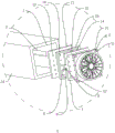
Fig. 2 is a schematic overall explosion diagram of an embodiment of the present application.
Fig. 3 is an enlarged schematic view at a in fig. 2.
Fig. 4 is a schematic cross-sectional view of an embodiment of the present application.
Fig. 5 is an enlarged schematic view at B in fig. 4.
Reference numerals: 1. a window frame main body; 2. a frame; 3. a vent hole; 4. a filter screen plate; 5. a fan; 6. a slider; 7. a chute; 8. connecting grooves; 9. a rotating wheel; 10. mounting blocks; 11. installing a bolt; 12. mounting holes; 13. a first dehumidification plate; 14. a second dehumidification plate; 15. an air inlet hole; 16. an air outlet; 17. a dehumidification chamber; 18. a desiccant; 19. positioning a plate; 20. a rubber ring; 21. an annular groove; 22. a limiting rod; 23. a limiting groove; 24. a vent pipe; 25. a guide plate.
Detailed Description
The present application is described in further detail below with reference to figures 1-5.
The embodiment of the application discloses outer sunshade integration system flat-open window is with rolling up curtain upper ledge section bar.
As shown in fig. 1, 2 and 3, the roller shutter upper frame section for the casement window of the external sunshade integrated system comprises a window frame main body 1, wherein the window frame main body 1 is fixedly connected with a frame 2 along the outer edge, the frame 2 is provided with a ventilation hole 3, the ventilation hole 3 is communicated with indoor and outdoor air, a ventilation pipe 24 is fixedly connected in the ventilation hole 3, and a filter screen plate 4 for sealing the ventilation pipe is connected in the ventilation pipe 24. Therefore, the arrangement of the filter screen plate 4 reduces the possibility that external dust directly enters the room through the vent holes 3 along with external airflow, thereby improving the cleanness of the external airflow entering the room; the arrangement of the vent holes 3 enables external air flow to be directly exchanged with indoor air through the vent holes 3, thereby improving the ventilation effect of the window frame main body 1.
As shown in fig. 3, a fan 5 is connected in a ventilation pipe 24, a filter screen plate 4 is located between the fan 5 and the second filter screen plate 4, an air inlet end of the fan 5 is arranged towards the room, an installation block 10 is uniformly and fixedly connected to the wall of the ventilation pipe 24 along four corners, four installation bolts 11 are arranged on the fan 5 in a penetrating mode and in threaded connection, four installation holes 12 matched with the installation bolts 11 are respectively formed in the four installation blocks 10, and the four installation bolts 11 are respectively in threaded connection with the four installation holes 12. Therefore, the provision of the fan 5 further enhances the exchange of the outdoor air with the indoor air, thereby enhancing the ventilation effect of the window frame body 1; when the fan 5 needs to be disassembled, a worker can disassemble the mounting bolt 11 from the mounting hole 12 by rotating the mounting bolt 11, and pull the fan 5 to take the fan 5 out of the ventilation pipe 24, so that the worker can repair or replace the fan 5.
As shown in fig. 3, two sliding blocks 6 are fixedly connected to the filter screen plate 4 along the horizontal direction, two sliding grooves 7 matched with the sliding blocks 6 are formed in the pipe wall of the ventilation pipe 24, the two sliding blocks 6 are connected to the two sliding grooves 7 in a sliding mode respectively, a connecting groove 8 is formed in the end face, facing the ground, of each sliding block 6, the connecting groove 8 is rotatably connected with a rotating wheel 9 along the horizontal direction, the connecting groove 8 extends out of the rotating wheel 9, and the rotating wheel 9 abuts against the groove walls of the sliding grooves 7. Therefore, due to the arrangement of the rotating wheel 9, a worker can rapidly and conveniently dismount the filter screen plate 4 from the ventilation pipe 24, so that the dismounting efficiency of the filter screen plate 4 is improved; when the filter screen plate 4 needs to be detached, a worker can detach the filter screen plate 4 from the ventilation pipe 24 by pulling the filter screen plate 4, so that the worker can clean or replace the filter screen plate 4 conveniently.
As shown in fig. 4 and 5, a first dehumidification plate 13 is fixedly connected in the ventilation pipe 24, one side of the first dehumidification plate 13 facing the filter screen plate 4 is connected with a second dehumidification plate 14, the first dehumidification plate 13 is provided with a plurality of air inlet holes 15, the second dehumidification plate 14 is provided with a plurality of air outlet holes 16, a dehumidification cavity 17 is formed between the first dehumidification plate 13 and the second dehumidification plate 14, a dehumidification agent 18 is filled in the dehumidification cavity 17, a positioning plate 19 is fixedly connected in the ventilation pipe 24, a rubber ring 20 is bonded on the outer edge of the second dehumidification plate 14, an annular groove 21 matched with the rubber ring 20 is formed in the positioning plate 19, and the rubber ring 20 is tightly pressed between the second dehumidification plate 14 and the groove wall of the annular groove 21. Therefore, the arrangement of the dehumidifying agent 18 reduces the possibility that external water vapor directly enters the room along with the air flow, thereby improving the dryness of the air entering the room; when the dehumidifying agent 18 needs to be replaced, the worker can drive the second filter plate to be separated from the positioning plate 19 in a mode of drawing the air outlet 16, so that the worker can replace the dehumidifying agent 18 in the dehumidifying cavity 17.
As shown in fig. 5, the second dehumidifying plate 14 is fixedly connected with a limiting rod 22, the filter screen plate 4 is provided with a limiting groove 23 matched with the limiting rod 22, the limiting rod 22 abuts against the limiting groove 23, a guide groove is obliquely formed at an opening of the limiting rod 22, a guide plate 25 is fixedly connected to the guide groove, and a part of the guide plate 25 extends out of the guide groove. Therefore, the guide groove has an indicating and limiting effect, the limiting rod 22 can firstly contact with the groove wall of the guide groove and then tightly abut against the limiting groove 23 under the guidance of the groove wall of the guide groove 24, and therefore the efficiency of inserting the limiting rod 22 into the limiting groove 23 is improved; the arrangement of the limiting rod 22 makes the filter screen plate 4 not easy to generate displacement relative to the pipe wall of the ventilation pipe 24 under external force, so that the filter screen plate 4 can stably filter the air passing through the filter screen plate 4.
The implementation principle of the embodiment of the application is as follows: the staff can start fan 5 at first, and outdoor air is at first through dehumidification chamber 17 under fan 5's effect, and the air is with the dehumidification agent 18 of dehumidification intracavity 17 intussuseption abundant contact drying, then through filter plate 4, has reduced external dust and has taken into the indoor possibility along with the air, later through fan 5, enters into indoorly from fan 5's air-out end to the ventilation effect of window frame main part 1 has been promoted.
The above embodiments are preferred embodiments of the present application, and the protection scope of the present application is not limited by the above embodiments, so: all equivalent changes made according to the structure, shape and principle of the present application shall be covered by the protection scope of the present application.
Claims (8)
1. The utility model provides an outer sunshade integration system flat-open window is with rolling up curtain upper ledge section bar which characterized in that: including window frame main part (1), be equipped with frame (2) on window frame main part (1), ventilation hole (3) have been seted up on frame (2), be equipped with ventilation pipe (24) in ventilation hole (3), be equipped with in ventilation pipe (24) and be used for sealing filter screen board (4) of ventilation pipe (24), be equipped with fan (5) in ventilation pipe (24), the air-out end of fan (5) sets up towards the outdoor.
2. The roller shutter upper frame section bar for the integrated external sunshade system casement window according to claim 1, characterized in that: the filter screen plate (4) is provided with a plurality of sliding blocks (6), the wall of the ventilation pipe (24) is provided with a plurality of sliding grooves (7) matched with the sliding blocks (6), and the sliding blocks (6) are respectively connected in the sliding grooves (7) in a sliding manner.
3. The roller shutter upper frame section bar for the integrated external sunshade system casement window according to claim 2, characterized in that: the slider (6) is provided with a connecting groove (8), the connecting groove (8) is rotationally connected with a rotating wheel (9), the connecting groove (8) extends out of the rotating wheel (9), and the rotating wheel (9) is in contact with the groove wall of the sliding groove (7).
4. The roller shutter upper frame section bar for the integrated external sunshade system casement window according to claim 1, characterized in that: the fan is characterized in that a plurality of mounting blocks (10) are arranged on the pipe wall of the ventilation pipe (24), the fan (5) is provided with a plurality of mounting bolts (11) in a penetrating mode and in threaded connection, mounting holes (12) matched with the mounting bolts (11) are formed in the mounting blocks (10), and the mounting bolts (11) are respectively in threaded connection in the mounting holes (12).
5. The roller shutter upper frame section bar for the integrated external sunshade system casement window according to claim 3, characterized in that: be equipped with first dehumidification board (13) in ventilation pipe (24), be equipped with second dehumidification board (14) in ventilation pipe (24), shown second dehumidification board (14) are located between first dehumidification board (13) and filter screen board (4), a plurality of fresh air inlet (15) have been seted up on first dehumidification board (13), a plurality of exhaust vents (16) have been seted up on second dehumidification board (14), form dehumidification chamber (17) between first dehumidification board (13) and second dehumidification board (14), dehumidification chamber (17) intussuseption is filled with desiccant (18).
6. The roller shutter upper frame section bar for the integrated external sunshade system casement window according to claim 5, characterized in that: a positioning plate (19) is arranged in the ventilation pipe (24), a rubber ring (20) is arranged on the outer edge of the second dehumidification plate (14), an annular groove (21) matched with the rubber ring (20) is formed in the positioning plate (19), and the rubber ring (20) is tightly abutted in the annular groove (21).
7. The roller shutter upper frame section bar for the integrated external sunshade system casement window according to claim 6, characterized in that: the second dehumidification plate (14) is provided with a limiting rod (22), the filter screen plate (4) is provided with a limiting groove (23) matched with the limiting rod (22), and the limiting rod (22) abuts against the limiting groove (23).
8. The roller shutter upper frame profile for the integrated external sunshade system casement window according to claim 7, characterized in that: a guide groove is obliquely formed in the opening of the limiting groove (23), a guide plate (25) is arranged on the guide groove, and the guide plate (25) partially extends out of the guide groove.
Priority Applications (1)
| Application Number | Priority Date | Filing Date | Title |
|---|---|---|---|
| CN202121700775.1U CN215332276U (en) | 2021-07-23 | 2021-07-23 | Outer sunshade integration system flat-open window is with rolling up curtain upper ledge section bar |
Applications Claiming Priority (1)
| Application Number | Priority Date | Filing Date | Title |
|---|---|---|---|
| CN202121700775.1U CN215332276U (en) | 2021-07-23 | 2021-07-23 | Outer sunshade integration system flat-open window is with rolling up curtain upper ledge section bar |
Publications (1)
| Publication Number | Publication Date |
|---|---|
| CN215332276U true CN215332276U (en) | 2021-12-28 |
Family
ID=79572312
Family Applications (1)
| Application Number | Title | Priority Date | Filing Date |
|---|---|---|---|
| CN202121700775.1U Active CN215332276U (en) | 2021-07-23 | 2021-07-23 | Outer sunshade integration system flat-open window is with rolling up curtain upper ledge section bar |
Country Status (1)
| Country | Link |
|---|---|
| CN (1) | CN215332276U (en) |
-
2021
- 2021-07-23 CN CN202121700775.1U patent/CN215332276U/en active Active
Similar Documents
| Publication | Publication Date | Title |
|---|---|---|
| CN206256847U (en) | A kind of Louver window with change room ventilation effect | |
| CN210320474U (en) | Energy-saving ventilation device for green building | |
| CN215332276U (en) | Outer sunshade integration system flat-open window is with rolling up curtain upper ledge section bar | |
| CN105649519A (en) | Integrated window | |
| CN208753767U (en) | A kind of outdoor protection type electric control cabinet based on Internet of Things | |
| CN208431904U (en) | A kind of ceiling mounting type fresh air-changing device of included static pressure distributor | |
| CN112267806B (en) | Aluminum alloy door and window with new trend system | |
| CN213952823U (en) | Energy-saving ventilating duct for building ventilation | |
| CN212984305U (en) | Curtain wall with ventilation structure | |
| CN215483904U (en) | Internal circulation double-layer curtain wall | |
| CN208650469U (en) | It is a kind of with the ventilating shaft for changing wind channel | |
| CN205477314U (en) | Integration window | |
| CN212204870U (en) | Inside air purification device of car elevator | |
| WO2022041776A1 (en) | Plant air treatment apparatus, and method for using same | |
| CN220489349U (en) | Energy-saving ventilation device for building | |
| CN217109868U (en) | Building energy-saving air interchanger | |
| CN216868731U (en) | Building energy-saving circulating ventilation device | |
| CN216076902U (en) | Protective door with ventilation assembly | |
| CN105464557B (en) | Door and window | |
| CN219138188U (en) | Sunshade with dust fall structure | |
| CN205536354U (en) | Novel power ventilator | |
| CN217206925U (en) | Centrifugal fire-fighting smoke exhaust fan | |
| CN218374775U (en) | Ceiling type four-side ventilating window | |
| CN108692413A (en) | A kind of air exchange machine | |
| CN215637789U (en) | Ventilation system |
Legal Events
| Date | Code | Title | Description |
|---|---|---|---|
| GR01 | Patent grant | ||
| GR01 | Patent grant |