CN215331909U - Safety protection rail is used in road and bridge construction - Google Patents
Safety protection rail is used in road and bridge construction Download PDFInfo
- Publication number
- CN215331909U CN215331909U CN202121411546.8U CN202121411546U CN215331909U CN 215331909 U CN215331909 U CN 215331909U CN 202121411546 U CN202121411546 U CN 202121411546U CN 215331909 U CN215331909 U CN 215331909U
- Authority
- CN
- China
- Prior art keywords
- rods
- sliding
- blocks
- road
- rotating
- Prior art date
- Legal status (The legal status is an assumption and is not a legal conclusion. Google has not performed a legal analysis and makes no representation as to the accuracy of the status listed.)
- Active
Links
Images


Landscapes
- Refuge Islands, Traffic Blockers, Or Guard Fence (AREA)
Abstract
The utility model belongs to the technical field of protective guards, in particular to a safety protective fence for road and bridge construction, aiming at the problems that the prior protective guard is mostly carried manually when moving, the labor intensity of workers is increased, and the occupied space is large when storing, the utility model provides a scheme which comprises a main supporting column, telescopic rods are fixedly arranged on both sides of the main supporting column, secondary supporting columns are fixedly connected on both telescopic rods, an inner cavity is arranged in the main supporting column, a motor is fixedly arranged in the inner cavity, an output shaft of the motor is connected with an extension mechanism, the extension mechanism comprises two rotating wheels, a belt, two screw rods, two sliding blocks, two first connecting rods, two second connecting rods and two connecting blocks, when moving is needed, the workers do not need to move manually, and the labor intensity of the workers is reduced, and when the storage box is stored, the occupied space is small, and the use is convenient.
Description
Technical Field
The utility model relates to the technical field of protective fences, in particular to a safety protective fence for road and bridge construction.
Background
In recent years, the pace of urbanization construction is accelerated continuously, houses and roads are built and repaired in various villages and towns, so that the requirement on equipment for road construction is greatly improved, the guard rail is one of indispensable tools for road construction, can well isolate vehicles coming and going, ensures the safety of construction environment, can ensure the safety of vehicle running, and can move along with the maintenance of the roads when in use.
When the existing guard rail is moved, manual carrying is mostly adopted, the labor intensity of workers is increased, and the occupied space is large when the guard rail is stored.
SUMMERY OF THE UTILITY MODEL
The utility model aims to solve the defects that the labor intensity of workers is increased due to the fact that most of existing protective fences are carried manually when the existing protective fences are moved, and the occupied space is large when the existing protective fences are stored, and provides a safety protective fence for road and bridge construction.
In order to achieve the purpose, the utility model adopts the following technical scheme:
a safety protection fence for road and bridge construction comprises a main support column, telescopic rods are fixedly arranged on two sides of the main support column, secondary support columns are fixedly connected to the two telescopic rods and are of a hollow structure, an inner cavity is formed in the main support column, a motor is fixedly arranged in the inner cavity, an output shaft of the motor is connected with an extension mechanism, the extension mechanism comprises two rotating wheels, a belt, two screw rods, two sliding blocks, two first connecting rods, two second connecting rods and two connecting blocks, one rotating wheel of the two rotating wheels is fixedly connected with an output shaft of the motor, the other rotating wheel of the two rotating wheels is rotatably arranged in the inner cavity, the outer sides of the two rotating wheels are in transmission connection with the same belt, the two sliding blocks are fixedly connected with the two screw rods, the two sliding blocks are in threaded connection with the two screw rods and are in sliding connection with the same inner cavity, the one end and two sliding blocks of two head rods rotate to be connected, and the other end and two time support columns of two head rods rotate to be connected, and the one end and the main tributary support column of two second connecting rods rotate to be connected, and the other end and two connecting blocks of two second connecting rods rotate to be connected, and two head rods rotate with two second connecting rods respectively to be connected, and two connecting blocks slide and set up in two time support columns, be provided with telescopic machanism in the support column once.
Preferably, telescopic machanism includes sliding column, two dwang, two supporting legs, two the dwang rotates with same sliding column to be connected, and two dwang rotate with two supporting legs to be connected, two supporting legs and same inferior support column sliding connection, and telescopic machanism has two, two the mechanism sets up in two inferior support columns, two sliding columns and two connecting block fixed connection in two telescopic machanism.
Preferably, two all be provided with the gyro wheel on the inferior support column, all rotate on two gyro wheels and be connected with the installation piece, fixedly on two installation pieces be provided with two sliding plates.
Preferably, the two secondary support columns are rotatably provided with screw rods, the two screw rods are in threaded connection with the two sliding plates, and the two sliding plates are in sliding connection with the two secondary support columns.
Compared with the prior art, the utility model has the advantages that:
(1) this scheme is owing to set up mutually supporting of runner, belt, screw rod, sliding block, head rod, second connecting rod and connecting block, can expand the rail guard when using to make the rail guard reclose when not using, practice thrift the parking space, facilitate the use.
(2) This scheme is owing to set up mutually supporting of slip post, dwang and supporting leg, can enlarge the extension length of supporting leg when the rail guard expandes, improves stability, and the practicality is strong.
(3) This scheme is owing to set up mutually supporting of gyro wheel, installation piece, sliding plate and lead screw, can make the gyro wheel withdrawal or stretch out secondary support column at any time, and the convenient removal.
When the mobile phone is required to be moved, workers do not need to carry the mobile phone manually, the labor intensity of the workers is reduced, and the mobile phone is small in occupied space and convenient to use when stored.
Drawings
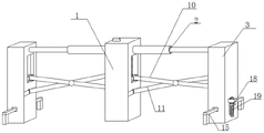
FIG. 1 is a schematic perspective view of a safety fence for road and bridge construction according to the present invention;
FIG. 2 is a schematic front view of a safety fence for road and bridge construction according to the present invention;
fig. 3 is a schematic side view of a safety protection fence for road and bridge construction according to the present invention.
In the figure: 1. a main support column; 2. a telescopic rod; 3. a secondary support column; 4. an inner cavity; 5. a motor; 6. a rotating wheel; 7. a belt; 8. a screw; 9. a slider; 10. a first connecting rod; 11. a second connecting rod; 12. connecting blocks; 13. a sliding post; 14. rotating the rod; 15. supporting legs; 16. a roller; 17. mounting blocks; 18. a sliding plate; 19. and a screw rod.
Detailed Description
The technical solutions in the embodiments will be described clearly and completely with reference to the drawings in the embodiments, and it is obvious that the described embodiments are only a part of the embodiments, but not all embodiments.
Referring to fig. 1-3, a safety protection fence for road and bridge construction comprises a main support column 1, telescopic rods 2 are fixedly arranged on both sides of the main support column 1, secondary support columns 3 are fixedly connected to both the telescopic rods 2, both the secondary support columns 3 are of a hollow structure, an inner cavity 4 is formed in the main support column 1, a motor 5 is fixedly arranged in the inner cavity 4, an extension mechanism is connected to an output shaft of the motor 5, the extension mechanism comprises two rotating wheels 6, a belt 7, two screw rods 8, two sliding blocks 9, two first connecting rods 10, two second connecting rods 11 and two connecting blocks 12, one rotating wheel 6 of the two rotating wheels 6 is fixedly connected with the output shaft of the motor 5, the other rotating wheel 6 of the two rotating wheels 6 is rotatably arranged in the inner cavity 4, the outer sides of the two rotating wheels 6 are in transmission connection with the same belt 7, and the two rotating wheels 6 are fixedly connected with the two screw rods 8, two sliding blocks 9 and two 8 threaded connection of screw rod, two sliding blocks 9 and same 4 sliding connection in inner chamber, the one end and two sliding blocks 9 of two head rods 10 rotate to be connected, the other end and two time support columns 3 of two head rods 10 rotate to be connected, the one end and the main tributary dagger 1 of two second connecting rods 11 rotate to be connected, the other end and two connecting blocks 12 of two second connecting rods 11 rotate to be connected, two head rods 10 rotate with two second connecting rods 11 respectively to be connected, two connecting blocks 12 slide and set up in two time support columns 3, be provided with telescopic machanism in the time support column 3.
In this embodiment, telescopic machanism includes sliding column 13, two dwang 14, two supporting legs 15, and two dwang 14 rotate with same sliding column 13 to be connected, and two dwang 14 rotate with two supporting legs 15 to be connected, and two supporting legs 15 and 3 sliding connection of same inferior support column, and telescopic machanism has two, and two mechanism settings are in two inferior support columns 3, two sliding column 13 and two connecting block 12 fixed connection in two telescopic machanism.
In this embodiment, the two secondary support columns 3 are all provided with rollers 16, the two rollers 16 are all rotatably connected with mounting blocks 17, and the two mounting blocks 17 are fixedly provided with two sliding plates 18.
In this embodiment, the two secondary support columns 3 are rotatably provided with the screw rods 19, the two screw rods 19 are in threaded connection with the two sliding plates 18, and the two sliding plates 18 are in sliding connection with the two secondary support columns 3.
In this embodiment, when in use, the motor 5 is started, the motor 5 drives the two screw rods 8 to rotate through the two rotating wheels 6 and the belt 7, the thread directions on the two screw rods 8 are opposite, so that the two screw rods 8 drive the two sliding blocks 9 to slide downwards, the two sliding blocks 9 drive the two first connecting rods 10 to rotate when sliding downwards, one ends of the two first connecting rods 10 are rotatably arranged on the two secondary supporting columns 3, so that the two secondary supporting columns 3 move, and the moving directions of the two secondary supporting columns 3 are opposite, so as to realize the extending effect, the guard rail is opened, when the two secondary supporting columns 3 extend, the two connecting blocks 12 slide downwards, at this time, the connecting blocks 12 drive the telescoping mechanism to move, the connecting blocks 12 drive the sliding columns 13 to slide downwards, the sliding columns 13 extrude the two rotating rods 14, so that the two rotating rods 14 rotate, so that the two rotating rods 14 drive the two supporting legs 15 to extend out, and the telescopic mechanism has two, and then can make the supporting leg 15 in two telescopic mechanisms stretch out simultaneously, strengthen the stability of the protective guard, when the protective guard is fully opened, the staff rotates two lead screws 19, two lead screws 19 pass two sliding plates 18, two mounting blocks 17 retract two gyro wheels 16 in two secondary support columns 3, the gyro wheel 16 takes place to move when avoiding using, finish using or need to move the protective guard, only need through the reverse transmission of the above-mentioned transmission, make two gyro wheels 16 contact with ground again, and reverse the starter motor 5 and make the protective guard close, it can to promote the protective guard directly afterwards, facilitate the use.
The above descriptions are only preferred embodiments of the present invention, but the scope of the present invention is not limited thereto, and any person skilled in the art should be considered to be within the scope of the present invention, and the technical solutions and the utility model concepts of the present invention are equivalent to, replaced or changed.
Claims (4)
1. The safety protection fence for road and bridge construction comprises a main supporting column (1) and is characterized in that telescopic rods (2) are fixedly arranged on two sides of the main supporting column (1), secondary supporting columns (3) are fixedly connected to the two telescopic rods (2), the two secondary supporting columns (3) are of a hollow structure, an inner cavity (4) is formed in the main supporting column (1), a motor (5) is fixedly arranged in the inner cavity (4), and an output shaft of the motor (5) is connected with an extension mechanism;
the extension mechanism comprises two rotating wheels (6), a belt (7), two screw rods (8), two sliding blocks (9), two first connecting rods (10), two second connecting rods (11) and two connecting blocks (12), wherein one rotating wheel (6) of the two rotating wheels (6) is fixedly connected with an output shaft of a motor (5), the other rotating wheel (6) of the two rotating wheels (6) is rotatably arranged in an inner cavity (4), the outer sides of the two rotating wheels (6) are in transmission connection with the same belt (7), the two rotating wheels (6) are fixedly connected with the two screw rods (8), the two sliding blocks (9) are in threaded connection with the two screw rods (8), the two sliding blocks (9) are in sliding connection with the same inner cavity (4), one ends of the two first connecting rods (10) are rotatably connected with the two sliding blocks (9), the other ends of the two first connecting rods (10) are rotatably connected with the two secondary supporting columns (3), one end of two second connecting rods (11) is rotated with main tributary dagger (1) and is connected, and the other end and two connecting blocks (12) of two second connecting rods (11) are rotated and are connected, and two head rod (10) rotate with two second connecting rods (11) respectively and are connected, and two connecting blocks (12) slide and set up in two secondary daggers (3), be provided with telescopic machanism in secondary dagger (3).
2. The safety protection fence for the construction of the road and bridge as claimed in claim 1, wherein the telescoping mechanism comprises a sliding column (13), two rotating rods (14) and two supporting legs (15), two rotating rods (14) are rotatably connected with the same sliding column (13), two rotating rods (14) are rotatably connected with the two supporting legs (15), two supporting legs (15) are slidably connected with the same secondary supporting column (3), and two telescoping mechanisms are provided, two mechanisms are arranged in the two secondary supporting columns (3), and the two sliding columns (13) in the two telescoping mechanisms are fixedly connected with the two connecting blocks (12).
3. The safety protection fence for road and bridge construction according to claim 1, wherein two secondary supporting columns (3) are respectively provided with a roller (16), two rollers (16) are respectively rotatably connected with a mounting block (17), and two sliding plates (18) are fixedly arranged on the two mounting blocks (17).
4. The safety protection fence for road and bridge construction according to claim 3, wherein the two secondary supporting columns (3) are rotatably provided with screw rods (19), the two screw rods (19) are in threaded connection with the two sliding plates (18), and the two sliding plates (18) are in sliding connection with the two secondary supporting columns (3).
Priority Applications (1)
| Application Number | Priority Date | Filing Date | Title |
|---|---|---|---|
| CN202121411546.8U CN215331909U (en) | 2021-06-24 | 2021-06-24 | Safety protection rail is used in road and bridge construction |
Applications Claiming Priority (1)
| Application Number | Priority Date | Filing Date | Title |
|---|---|---|---|
| CN202121411546.8U CN215331909U (en) | 2021-06-24 | 2021-06-24 | Safety protection rail is used in road and bridge construction |
Publications (1)
| Publication Number | Publication Date |
|---|---|
| CN215331909U true CN215331909U (en) | 2021-12-28 |
Family
ID=79561178
Family Applications (1)
| Application Number | Title | Priority Date | Filing Date |
|---|---|---|---|
| CN202121411546.8U Active CN215331909U (en) | 2021-06-24 | 2021-06-24 | Safety protection rail is used in road and bridge construction |
Country Status (1)
| Country | Link |
|---|---|
| CN (1) | CN215331909U (en) |
Cited By (1)
| Publication number | Priority date | Publication date | Assignee | Title |
|---|---|---|---|---|
| CN114856306A (en) * | 2022-05-23 | 2022-08-05 | 江西经匠建设有限公司 | Guardrail is used in town road bridge construction |
-
2021
- 2021-06-24 CN CN202121411546.8U patent/CN215331909U/en active Active
Cited By (2)
| Publication number | Priority date | Publication date | Assignee | Title |
|---|---|---|---|---|
| CN114856306A (en) * | 2022-05-23 | 2022-08-05 | 江西经匠建设有限公司 | Guardrail is used in town road bridge construction |
| CN114856306B (en) * | 2022-05-23 | 2023-09-15 | 山东冠县万庆德交通设施有限公司 | Guardrail for municipal road and bridge construction |
Similar Documents
| Publication | Publication Date | Title |
|---|---|---|
| CN215331909U (en) | Safety protection rail is used in road and bridge construction | |
| CN219344256U (en) | Rail guard and road construction isolating device | |
| CN209854585U (en) | Isolating device for municipal construction | |
| CN215485168U (en) | Convenient foldable fence used in road and bridge construction process | |
| CN215107926U (en) | Fender is enclosed in municipal works construction | |
| CN210684560U (en) | Municipal afforestation guardrail | |
| CN214886147U (en) | Building construction safety device | |
| CN215219773U (en) | Forbidden license plate detection device of underground parking garage door | |
| CN108556676A (en) | A kind of charging pile for electric vehicle with rainwater-proof function | |
| CN214273154U (en) | Tent moving system | |
| CN211899547U (en) | Detachable supporting table for building platform | |
| CN214498346U (en) | A remove support for high slope drilling support | |
| CN114715821A (en) | Environment-friendly information communication is maintenance support for basic station | |
| CN208950371U (en) | A kind of adjustable traffic police's platform | |
| CN210459059U (en) | Roll-over stand of road guardrail washing usefulness | |
| CN217461710U (en) | Electric power operation is with protection rail | |
| CN217712066U (en) | Civil construction protective fence | |
| CN219316587U (en) | Electrical safety protection device | |
| CN218991141U (en) | Multifunctional protective guard for building | |
| CN217174510U (en) | Road safety protection device | |
| CN220469270U (en) | Canopy flexible traction structure | |
| CN110080143B (en) | Roll-over stand for cleaning road guardrail | |
| CN218275810U (en) | Insulating protection device for electric power construction | |
| CN212350206U (en) | Reinforcing bar hoop bending equipment for building | |
| CN220188321U (en) | Telescopic water interception auxiliary tool for water closing test |
Legal Events
| Date | Code | Title | Description |
|---|---|---|---|
| GR01 | Patent grant | ||
| GR01 | Patent grant |