Hydraulic engineering pipeline surface rust cleaning device
Technical Field
The utility model relates to the technical field of hydraulic engineering, in particular to a rust removing device for the outer surface of a hydraulic engineering pipeline.
Background
At present, a pipeline is a device for conveying gas, liquid or fluid with solid particles, which is formed by connecting pipes, pipe connectors, valves and the like, generally, after the fluid is pressurized by a blower, a compressor, a pump, a boiler and the like, the fluid flows from a high-pressure part to a low-pressure part of the pipeline, and the fluid can also be conveyed by utilizing the pressure or gravity of the fluid, so that the pipeline has wide application range and is mainly used in water supply, drainage, heat supply, gas supply, long-distance petroleum and natural gas conveying, agricultural irrigation, hydraulic engineering and various industrial devices.
The prior patent (publication number CN112643506U) a hydraulic engineering pipeline external surface rust cleaning device includes: pipeline, its innovation point lies in: the grinding device also comprises a concave character seat, a pulley lever, a pulley, a first motor, a belt, a pneumatic cylinder, a beam, a housing, a sliding rail, a sliding block, a screw rod, a second motor, a third motor and a grinding disc; pulley rods are fixedly connected to two sides of the inner portion of the top end of the concave character seat, and pulleys are movably connected to the pulley rods; the pipeline is positioned between the pulleys; a first motor is fixedly connected to the center position inside the top end of the concave character seat; the output end of the first motor is connected with the input end of the left pulley through a belt; pneumatic cylinders are fixedly connected to two sides of the upper surface of the concave character seat; the cross beam is fixedly connected to an output shaft of the pneumatic cylinder; the lower surface of the cross beam is fixedly connected with a housing; the sliding rail is fixedly connected to the top end inside the housing cavity, and the screw rod is movably connected to the housing cavity.
In the process of implementing the utility model, the inventor finds that at least the following problems in the prior art are not solved: go up patent though can be rational in infrastructure simple, low in production cost, simple to operate, it is multiple functional, start first motor drive pulley and rotate for the pipeline rotates, and the third motor drives the mill rotation and polishes the pipeline, but: 1. the rust after rust removal is not treated, resulting in rust on the workbench and the surroundings; 2. the back-and-forth movement of the hydraulic engineering pipeline cannot be adjusted, and manual pushing is required.
SUMMERY OF THE UTILITY MODEL
The utility model aims to provide a rust removing device for the outer surface of a hydraulic engineering pipeline, which solves the problems in the background technology.
In order to achieve the purpose, the utility model provides the following technical scheme: a rust removing device for the outer surface of a hydraulic engineering pipeline comprises a workbench, wherein support frames are fixedly connected to the left end and the right end of the side wall of the workbench, a first support is fixedly arranged on the left side of the side wall of the workbench, a driving roller is movably arranged on the first support, a second support is fixedly arranged on the right side of the first support, a plurality of groups of driven wheels which are uniformly distributed are arranged in the second support, an electric push rod A is fixedly arranged in the middle of the upper side of the support frames, and a cleaning mechanism is fixedly connected to the lower side of the electric push rod A through the support frames;
clearance mechanism is including intercommunication box and cleaning plate, intercommunication box and cleaning plate all are the arc, intercommunication box inboard and cleaning plate outside fixed connection, set up the through-hole that the multiunit equidistance distributes on the cleaning plate, the multiunit the through-hole all with intercommunication box communicates each other, cleaning plate inboard all leads to multiunit spring fixedly connected with steel wire rust cleaning brush.
As a preferred embodiment of the utility model, the upper end of the right side wall of the support frame is provided with a collecting box, the upper end of the collecting box is connected with the communicating box through a connecting pipe, an exhaust fan is fixedly arranged on the connecting pipe, and an air outlet of the exhaust fan is communicated with the connecting pipe.
In a preferred embodiment of the present invention, stoppers are fixedly connected to both left and right ends of the inner side of the cleaning plate, and the stoppers are rubber stoppers.
As a preferred embodiment of the present invention, a groove is formed in the upper end of the left side wall of the second support, piston holes are formed in the front side and the rear side of the groove, two groups of piston holes are movably connected with piston rods, a plurality of groups of driven wheels are movably mounted on the piston rods through a plurality of groups of rotating shafts and are distributed at equal intervals, fixing plates are fixedly connected to the lower ends of the front side wall and the rear side wall of the groove, and the fixing plates are movably connected with the plurality of groups of driven wheels through the rotating shafts.
As a preferred embodiment of the present invention, a motor is fixedly installed on the front side of the first support, a driving output end of the motor is in transmission connection with a transmission shaft, the transmission shaft penetrates through the first support and is fixedly connected with the driving roll, an electric push rod B is fixedly installed on the right side of the second support, and the electric push rod B is fixedly connected with the front end of the piston rod through a connecting rod.
Compared with the prior art, the utility model has the following beneficial effects:
1. according to the utility model, the cleaning mechanism fixedly connected with the support frame in a penetrating manner through the lower side of the electric push rod A comprises the communication box, the cleaning plate and the steel wire rust removing brush, when the electric push rod A is driven to mutually fit the steel wire rust removing brush with the outer surface of the hydraulic engineering pipeline needing rust removal, the steel wire rust removing brush can remove a large amount of rust, and meanwhile, the through holes communicated with the communication box have strong suction force to adsorb a large amount of rust into the collection box, so that the cleanness of the workbench and the treatment of the rust are ensured, and the hydraulic engineering pipeline outer surface rust removing device is more practically used.
2. According to the utility model, as the piston rods movably connected with the two groups of piston holes are movably provided with the plurality of groups of driven wheels distributed at equal intervals through the plurality of groups of rotating shafts, and the fixed rods fixedly connected with the lower ends of the front side wall and the rear side wall of the groove are movably connected with the plurality of groups of driven wheels through the rotating shafts, when the piston rods are pushed forwards and backwards, the direction of the driven wheels can be regulated, the engineering pipeline needing to be derusted can move forwards and backwards conveniently, and the device for derusting the outer surface of the hydraulic engineering pipeline can be used more practically.
Drawings
Other features, objects and advantages of the utility model will become more apparent upon reading of the detailed description of non-limiting embodiments with reference to the following drawings:
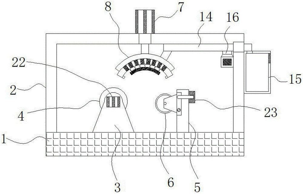
FIG. 1 is a schematic overall structure diagram of a rust removing device for the outer surface of a hydraulic engineering pipeline;
FIG. 2 is a schematic structural diagram of a cleaning mechanism of the rust removing device for the outer surface of the hydraulic engineering pipeline;
FIG. 3 is a schematic cross-sectional view of a second bracket of the rust removing device for the outer surface of the hydraulic engineering pipeline.
In the figure: 1. a work table; 2. a support frame; 3. a first bracket; 4. a drive roll; 5. a second bracket; 6. a driven wheel; 7. an electric push rod A; 8. a cleaning mechanism; 9. a communication box; 10. cleaning the plate; 11. a through hole; 12. a spring; 13. a steel wire rust removing brush; 14. a connecting pipe; 15. a collection box; 16. an exhaust fan; 17. a stopper; 18. a groove; 19. a piston bore; 20. a piston rod; 21. fixing the rod; 22. a motor; 23. and an electric push rod B.
Detailed Description
In order to make the technical means, the creation characteristics, the achievement purposes and the effects of the utility model easy to understand, the utility model is further described with the specific embodiments.
In the description of the present invention, it is to be understood that the terms "upper", "lower", "front", "rear", "left", "right", "top", "bottom", "inner", "outer", and the like, indicate orientations or positional relationships based on the orientations or positional relationships shown in the drawings, are only for convenience in describing the present invention and simplifying the description, and do not indicate or imply that the device or element referred to must have a particular orientation, be constructed in a particular orientation, and be operated, and thus, should not be construed as limiting the present invention; in the description of the present invention, it should be noted that unless otherwise explicitly stated or limited, the terms "mounted," "connected," and "disposed" are to be construed broadly and can, for example, be fixedly connected, disposed, detachably connected, disposed, or integrally connected and disposed. The specific meanings of the above terms in the present invention can be understood in specific cases to those skilled in the art.
Referring to fig. 1-3, the present invention provides a technical solution: a rust removing device for the outer surface of a hydraulic engineering pipeline comprises a workbench 1, wherein support frames 2 are fixedly connected to the left end and the right end of the side wall of the workbench 1, a first support 3 is fixedly installed on the left side of the side wall of the workbench 1, a driving roller 4 is movably installed on the first support 3, a second support 5 is fixedly installed on the right side of the first support 3, a plurality of groups of driven wheels 6 which are uniformly distributed are arranged in the second support 5, an electric push rod A7 is fixedly installed in the middle of the upper side of the support frame 2, and a cleaning mechanism 8 is fixedly connected to the lower side of an electric push rod A7 in a penetrating mode with the support frames 2;
the cleaning mechanism 8 comprises a communication box 9 and a cleaning plate 10, the communication box 9 and the cleaning plate 10 are arc-shaped, the inner side of the communication box 9 is fixedly connected with the outer side of the cleaning plate 10, a plurality of groups of through holes 11 distributed at equal intervals are arranged on the cleaning plate 10, the through holes 11 are communicated with the communication box 9, the inner side of the cleaning plate 10 is fixedly connected with a steel wire derusting brush 13 through a plurality of groups of springs 12, the cleaning mechanism 8 fixedly connected with a support frame 2 through the lower side of an electric push rod A7 comprises the communication box 9, the cleaning plate 10 and the steel wire derusting brush 13, when the electric push rod A7 is driven to mutually attach the steel wire derusting brush 13 to the outer surface of a hydraulic engineering pipeline needing derusting, the steel wire derusting brush 13 can reject a large amount of iron, the through holes 11 communicated with the communication box 9 can have stronger suction, and adsorb a large amount of iron rust into a collection box 15, the clean and tidy treatment of the workbench and the rust are guaranteed, and the hydraulic engineering pipeline outer surface rust removing device is more practically used.
In this embodiment, 2 right side walls upper ends of support frame are provided with collecting box 15, 15 upper ends of collecting box through connecting pipe 14 with the box 9 that communicates is connected, fixed mounting has air exhauster 16 on the connecting pipe 14, air exhauster 16 air outlet with connecting pipe 14 communicates each other, collection iron rust that can be fine.
In this embodiment, both ends all fixedly connected with dog 17 about cleaning plate 10 inboard, dog 17 is the rubber dog, can block the splash of iron rust.
In this embodiment, a groove 18 is formed at the upper end of the left side wall of the second bracket 5, piston holes 19 are formed at the front side and the rear side of the groove 18, two sets of the piston holes 19 are movably connected with piston rods 20, a plurality of sets of driven wheels 6 distributed at equal intervals are movably mounted on the piston rods 20 through a plurality of sets of rotating shafts, fixing rods 21 are fixedly connected with the lower ends of the front side wall and the rear side wall of the groove 18, the fixing rods 21 are movably connected with the plurality of sets of the driven wheels 6 through the rotating shafts, a plurality of sets of the driven wheels 6 distributed at equal intervals are movably mounted on the piston rods 20 movably connected with the two sets of the piston holes 19 through a plurality of sets of rotating shafts, and the fixing rods 21 fixedly connected with the lower ends of the front side wall and the rear side wall of the groove 18 are movably connected with the plurality of the driven wheels 6 through the rotating shafts, so that when the piston rods 20 are pushed forwards and backwards, the direction of the driven wheels 6 can be adjusted, thereby facilitating the forward and backwards movement of the engineering pipeline needing rust removal, be favorable to more practical use hydraulic engineering pipeline surface rust cleaning device.
In this embodiment, a motor 22 is fixedly installed on the front side of the first support 3, a driving output end of the motor 22 is in transmission connection with a transmission shaft, the transmission shaft penetrates through the first support 3 and the driving roller 4, an electric push rod B is fixedly installed on the right side of the second support 5, and the electric push rod B23 is fixedly connected with the front end of the piston rod 20 through a connecting rod and can drive the driving roller 4 to rotate and drive the piston rod 20 to move back and forth.
When the rust removing device for the outer surface of the hydraulic engineering pipeline is used, it needs to be explained that the rust removing device for the outer surface of the hydraulic engineering pipeline is provided, all parts are universal standard parts or parts known by technicians in the field, and the structure and the principle of the rust removing device are known by the technicians through technical manuals or conventional experimental methods.
When in use, a plurality of groups of driven wheels 6 which are distributed equidistantly are movably arranged on piston rods 20 which are movably connected with two groups of piston holes 19 through a plurality of groups of rotating shafts, fixed rods 21 which are fixedly connected with the lower ends of the front side wall and the rear side wall of a groove 18 are movably connected with the plurality of groups of driven wheels 6 through the rotating shafts, when people push the piston rods 20 forwards and backwards, the direction of the driven wheels 6 can be adjusted, so that an engineering pipeline needing to be derusted can move forwards and backwards conveniently, meanwhile, a cleaning mechanism 8 which penetrates through a support frame 2 and is fixedly connected with the lower side of an electric push rod A7 comprises a communicating box 9, a cleaning plate 10 and a steel wire derusting brush 13, when the electric push rod A7 is driven to attach the steel wire derusting brush 13 to the outer surface of the hydraulic engineering pipeline needing to be derusted, the steel wire derusting brush 13 can remove a large amount of iron rust, the through holes 11 which are mutually communicated with the communicating box 9 can have stronger suction force, so as to absorb a large amount of iron rust into a collecting box 15, the cleanness and the rust treatment of the workbench are ensured, and finally the rust in the collecting box 15 is cleaned at regular time.
While there have been shown and described what are at present considered the fundamental principles and essential features of the utility model and its advantages, it will be apparent to those skilled in the art that the utility model is not limited to the details of the foregoing exemplary embodiments, but is capable of other specific forms without departing from the spirit or essential characteristics thereof. The present embodiments are therefore to be considered in all respects as illustrative and not restrictive, the scope of the utility model being indicated by the appended claims rather than by the foregoing description, and all changes which come within the meaning and range of equivalency of the claims are therefore intended to be embraced therein. Any reference sign in a claim should not be construed as limiting the claim concerned.
Furthermore, it should be understood that although the present description refers to embodiments, not every embodiment may contain only a single embodiment, and such description is for clarity only, and those skilled in the art should integrate the description, and the embodiments may be combined as appropriate to form other embodiments understood by those skilled in the art.