CN215252698U - Hydraulic engineering gate device - Google Patents
Hydraulic engineering gate device Download PDFInfo
- Publication number
- CN215252698U CN215252698U CN202121203181.XU CN202121203181U CN215252698U CN 215252698 U CN215252698 U CN 215252698U CN 202121203181 U CN202121203181 U CN 202121203181U CN 215252698 U CN215252698 U CN 215252698U
- Authority
- CN
- China
- Prior art keywords
- gate
- frame
- motor
- sleeve
- water conservancy
- Prior art date
- Legal status (The legal status is an assumption and is not a legal conclusion. Google has not performed a legal analysis and makes no representation as to the accuracy of the status listed.)
- Active
Links
Images


Abstract
The utility model discloses a hydraulic engineering gate device, including floodgate frame and movable mounting in the floodgate board of floodgate frame, the top of floodgate frame is provided with the crossbearer, and the bottom both ends of crossbearer fixed mounting have the support respectively, and the bottom fixed mounting of support at the top of floodgate frame, rotates between two supports and installs same bull stick, fixed cup joint has two to receive and release the wheel on the bull stick, and two receive and release the wheel and twine respectively and be provided with the haulage rope. The hydraulic engineering gate device provided by the utility model can ensure that the gate plate is positioned very firmly in the lifting process, has higher stability, and ensures the stable use of the gate in the lifting process; and the gate plate is lifted through mechanized operation, the trouble that manpower is needed to lift in the past is avoided, the working efficiency is improved, time and labor are saved, and the gate plate is convenient for people to use.
Description
Technical Field
The utility model relates to a hydraulic engineering technical field especially relates to a hydraulic engineering gate device.
Background
Hydraulic engineering is an engineering built for controlling and allocating surface water and underground water in the nature to achieve the purpose of removing harm and benefiting, and the hydraulic engineering needs to build different types of hydraulic buildings such as dams, dikes, spillways, sluice gates, water inlets, channels, transit troughs, rafts, fishways and the like to achieve the aims, wherein the application of the sluice gate is most important.
At present, in the lifting process of some water conservancy and hydropower gate lifting devices in the existing market, the phenomenon of rotation often occurs due to the infirm fixation of a traction rope, so that the gate is easy to sink, the stability is low, and the normal use of the gate in the lifting process is influenced; moreover, the work efficiency during lifting is reduced through manual operation. Therefore, we propose a hydraulic engineering gate device for solving the above problems.
SUMMERY OF THE UTILITY MODEL
The utility model aims at solving the defects existing in the prior art and providing a hydraulic engineering gate device.
In order to achieve the above purpose, the utility model adopts the following technical scheme:
a hydraulic engineering gate device comprises a gate frame and a gate plate movably arranged in the gate frame, wherein a cross frame is arranged above the gate frame, two ends of the bottom of the cross frame are respectively and fixedly provided with a support, the bottom of each support is fixedly arranged at the top of the gate frame, a same rotating rod is rotatably arranged between the two supports, the rotating rod is fixedly sleeved with two retractable wheels, the two retractable wheels are respectively wound with a traction rope, the bottom end of the traction rope is fixedly connected to the top of the gate plate, the bottom of the cross frame is fixedly provided with a first motor, the output end of the first motor is fixedly connected with a first bevel gear, the lower right side of the first bevel gear is meshed with a second bevel gear, and the second bevel gear is fixedly sleeved on the rotating rod;
still fixed cover has connect positioning gear on the bull stick, and the top fixed mounting of floodgate frame has the sleeve, has the lifter along vertical direction slidable mounting in the sleeve, and the top of lifter slides and runs through to telescopic top and fixedly connected with location latch, and location latch and positioning gear meshing location, the screw rod has been cup jointed through the screw thread in the bottom of lifter, and in the bottom of screw rod extended to the sleeve, fixed mounting had the second motor on the telescopic bottom inner wall, and the output of second motor and the bottom fixed connection of screw rod.
Preferably, the bottom of the lifting rod is provided with a thread groove, and the screw rod is in threaded connection with the thread groove.
Preferably, the bottom of the two sides of the lifting rod is provided with a sliding block, the inner walls of the two sides of the sleeve are provided with sliding grooves, and the sliding blocks are slidably mounted in the sliding grooves.
Preferably, the bottom of the gate plate is fixedly provided with a buffer rubber pad, the inner walls of the two sides of the gate frame are provided with sliding grooves, and the two sides of the gate plate are slidably mounted in the two sliding grooves along the vertical direction respectively.
Preferably, an electric cabinet is arranged on the left outer side of the support, a power supply and a switch are arranged in the electric cabinet, and the power supply and the switch are electrically connected with the first motor and the second motor.
Preferably, the inner sides of the two brackets are fixedly provided with bearing seats, and the two ends of the rotating rod are rotatably arranged on the two bearing seats respectively.
Compared with the prior art, the beneficial effects of the utility model are that:
in the utility model, when the gate plate needs to be lifted for use, the positioning of the positioning latch on the positioning gear is firstly released, then the first motor drives the first bevel gear to rotate, and the first bevel gear and the second bevel gear are meshed for transmission to drive the rotating rod and the retractable wheel to rotate, so that the traction rope is wound through the rotation of the retractable wheel, and the gate plate is lifted through the traction rope; after the lifting rod is lifted to a required position, the screw rod is driven to rotate reversely through the reverse rotation work of the output end of the second motor, the lifting rod can perform upward thread transmission on the screw rod through the thread groove, the lifting rod drives the positioning latch to move upwards, and then the positioning latch is enabled to perform meshing positioning on the positioning gear;
in summary, the hydraulic engineering gate device provided by the utility model can make the gate plate positioned very firmly in the lifting process, has higher stability, and ensures the stable use of the gate in the lifting process; and the gate plate is lifted through mechanized operation, the trouble that manpower is needed to lift in the past is avoided, the working efficiency is improved, time and labor are saved, and the gate plate is convenient for people to use.
Drawings
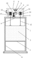
Fig. 1 is a schematic structural view of a hydraulic engineering gate device provided by the present invention;
FIG. 2 is an enlarged schematic view of a portion A of FIG. 1 according to the present invention;
fig. 3 is a schematic structural view between the positioning latch and the positioning gear of the present invention.
In the figure: the brake device comprises a brake frame 1, a brake plate 2, a buffer rubber pad 3, a sliding groove 4, a support 5, a cross frame 6, a first motor 7, a first bevel gear 8, a second bevel gear 9, a rotating rod 10, a retractable wheel 11, a traction rope 12, an electric cabinet 13, a bearing seat 14, a positioning gear 15, a sleeve 16, a second motor 161, a screw 162, a threaded groove 163, a lifting rod 164, a sliding block 165 and a positioning latch 166.
Detailed Description
The technical solutions in the embodiments of the present invention will be described clearly and completely with reference to the accompanying drawings in the embodiments of the present invention, and it is obvious that the described embodiments are only some embodiments of the present invention, not all embodiments.
Referring to fig. 1-3, a hydraulic engineering gate device comprises a gate frame 1 and a gate plate 2 movably mounted in the gate frame 1, wherein a cross frame 6 is arranged above the gate frame 1, two ends of the bottom of the cross frame 6 are respectively and fixedly provided with a support 5, the bottom of the support 5 is fixedly mounted at the top of the gate frame 1, a same rotating rod 10 is rotatably mounted between the two supports 5, two retractable wheels 11 are fixedly sleeved on the rotating rod 10, two retractable wheels 11 are respectively wound with a traction rope 12, the bottom end of the traction rope 12 is fixedly connected to the top of the gate plate 2, the bottom of the cross frame 6 is fixedly provided with a first motor 7, the output end of the first motor 7 is fixedly connected with a first bevel gear 8, the lower right side of the first bevel gear 8 is engaged with a second bevel gear 9, and the second bevel gear 9 is fixedly sleeved on the rotating rod 10;
still fixed cover has connect positioning gear 15 on the bull stick 10, and the top fixed mounting of floodgate frame 1 has sleeve 16, has lifter 164 along vertical direction slidable mounting in the sleeve 16, and the top of lifter 164 slides and runs through to sleeve 16's top and fixedly connected with location latch 166, and location latch 166 and positioning gear 15 meshing location, screw rod 162 has been cup jointed through the screw thread to the bottom of lifter 164, and in the bottom of screw rod 162 extended to sleeve 16, and fixed mounting has second motor 161 on the bottom inner wall of sleeve 16, and the output of second motor 161 and the bottom fixed connection of screw rod 162. The hydraulic engineering gate device provided by the utility model can ensure that the gate plate 2 is positioned very firmly in the lifting process, has higher stability, and ensures the stable use of the gate in the lifting process; and the gate plate 2 is lifted through mechanized operation, the trouble that manpower is needed to lift in the past is avoided, the working efficiency is improved, time and labor are saved, and the gate plate is convenient for people to use.
In this example, the bottom of the lifting rod 164 is provided with a threaded groove 163, and the screw 162 is in threaded connection with the threaded groove 163.
In this example, the bottom of the two sides of the lifting rod 164 is provided with a sliding block 165, the inner walls of the two sides of the sleeve 16 are provided with sliding grooves, and the sliding block 165 is slidably mounted in the sliding grooves.
In this example, the bottom of the gate plate 2 is further fixedly provided with a cushion rubber pad 3, the inner walls of the two sides of the gate frame 1 are both provided with sliding grooves 4, and the two sides of the gate plate 2 are respectively slidably mounted in the two sliding grooves 4 along the vertical direction.
In this example, the left outer side of the bracket 5 is provided with an electric cabinet 13, a power supply and a switch are arranged in the electric cabinet 13, and the power supply and the switch are electrically connected with the first motor 7 and the second motor 161.
In this example, bearing seats 14 are fixedly mounted on the inner sides of the two brackets 5, and both ends of the rotating rod 10 are rotatably mounted on the two bearing seats 14, respectively.
The utility model provides a water conservancy project gate device, when needing to promote the use to gate board 2, remove the location of location latch 166 to positioning gear 15 earlier, namely drive the screw rod 162 through second motor 161 and rotate, can make lifter 164 carry out screw drive down on screw rod 162 through thread groove 163, and lifter 164 drives location latch 166 to move down again when moving down, and then removes the meshing location of location latch 166 to positioning gear 15; then, the first motor 7 drives the first bevel gear 8 to rotate, the first bevel gear 8 and the second bevel gear 9 are in meshing transmission to drive the rotating rod 10 and the retracting wheel 11 to rotate, the retracting wheel 11 rotates to wind the traction rope 12, the brake plate 2 is lifted by the traction rope 12, after the brake plate is lifted to a required position, the screw 162 is driven to rotate reversely by the reverse rotation of the output end of the second motor 161, the lifting rod 164 can perform upward thread transmission on the screw 162 through the thread groove 163, the lifting rod 164 drives the positioning latch 166 to move upwards, the positioning latch 166 is further enabled to perform meshing positioning on the positioning gear 15, the positioning latch 166 is enabled to perform meshing positioning on the positioning gear 15, the rotating rod 10 and the traction rope 12 on the retracting wheel 11 can be prevented from rotating, and finally, the brake plate 2 can be positioned very firmly in the lifting process, the stability is higher, and the stable use of the gate in the lifting process is ensured; and through mechanized operation, the trouble that manpower is needed to lift the operation in the past is also avoided, and the working efficiency is improved.
The above, only be the concrete implementation of the preferred embodiment of the present invention, but the protection scope of the present invention is not limited thereto, and any person skilled in the art is in the technical scope of the present invention, according to the technical solution of the present invention and the utility model, the concept of which is equivalent to replace or change, should be covered within the protection scope of the present invention.
Claims (6)
1. A water conservancy project gate device comprises a gate frame (1) and a gate plate (2) movably arranged in the gate frame (1), and is characterized in that a cross frame (6) is arranged above the gate frame (1), two ends of the bottom of the cross frame (6) are respectively and fixedly provided with a support (5), the bottom of each support (5) is fixedly arranged at the top of the gate frame (1), a same rotating rod (10) is rotatably arranged between the two supports (5), two retractable wheels (11) are fixedly sleeved on the rotating rod (10), a traction rope (12) is respectively wound on the two retractable wheels (11), the bottom end of the traction rope (12) is fixedly connected to the top of the gate plate (2), a first motor (7) is fixedly arranged at the bottom of the cross frame (6), a first bevel gear (8) is fixedly connected to the output end of the first motor (7), and a second bevel gear (9) is meshed with the lower right side of the first bevel gear (8), and the second bevel gear (9) is fixedly sleeved on the rotating rod (10);
still fixed positioning gear (15) have been cup jointed on bull stick (10), the top fixed mounting of floodgate frame (1) has sleeve (16), has lifter (164) along vertical direction slidable mounting in sleeve (16), and the top of lifter (164) slides and runs through to top and fixedly connected with location latch (166) of sleeve (16), and location latch (166) and positioning gear (15) meshing location, screw rod (162) have been cup jointed through the screw thread in the bottom of lifter (164), and in the bottom of screw rod (162) extended to sleeve (16), fixed mounting had second motor (161) on the bottom inner wall of sleeve (16), and the output of second motor (161) and the bottom fixed connection of screw rod (162).
2. The gate structure of water conservancy project according to claim 1, wherein the bottom of the lifting rod (164) is provided with a screw groove (163), and the screw (162) is in threaded connection with the screw groove (163).
3. The gate device of water conservancy project according to claim 1, characterized in that the bottom of both sides of the lifting rod (164) is provided with a sliding block (165), the inner walls of both sides of the sleeve (16) are provided with a sliding groove, and the sliding block (165) is slidably mounted in the sliding groove.
4. The water conservancy project gate device according to claim 1, wherein a cushion rubber pad (3) is fixedly arranged at the bottom of the gate plate (2), sliding grooves (4) are formed in inner walls of two sides of the gate frame (1), and two sides of the gate plate (2) are respectively slidably mounted in the two sliding grooves (4) in the vertical direction.
5. The gate device of the water conservancy project according to claim 1, wherein an electric cabinet (13) is arranged on the left outer side of the support (5), a power supply and a switch are arranged in the electric cabinet (13), and the power supply and the switch are electrically connected with the first motor (7) and the second motor (161).
6. The gate device of water conservancy project according to claim 1, characterized in that bearing seats (14) are fixedly installed at the inner sides of the two brackets (5), and two ends of the rotating rod (10) are respectively rotatably installed on the two bearing seats (14).
Priority Applications (1)
| Application Number | Priority Date | Filing Date | Title |
|---|---|---|---|
| CN202121203181.XU CN215252698U (en) | 2021-06-01 | 2021-06-01 | Hydraulic engineering gate device |
Applications Claiming Priority (1)
| Application Number | Priority Date | Filing Date | Title |
|---|---|---|---|
| CN202121203181.XU CN215252698U (en) | 2021-06-01 | 2021-06-01 | Hydraulic engineering gate device |
Publications (1)
| Publication Number | Publication Date |
|---|---|
| CN215252698U true CN215252698U (en) | 2021-12-21 |
Family
ID=79475147
Family Applications (1)
| Application Number | Title | Priority Date | Filing Date |
|---|---|---|---|
| CN202121203181.XU Active CN215252698U (en) | 2021-06-01 | 2021-06-01 | Hydraulic engineering gate device |
Country Status (1)
| Country | Link |
|---|---|
| CN (1) | CN215252698U (en) |
Cited By (2)
| Publication number | Priority date | Publication date | Assignee | Title |
|---|---|---|---|---|
| CN114837140A (en) * | 2022-03-22 | 2022-08-02 | 珠江水利委员会珠江水利科学研究院 | Water conservancy water and electricity gate opening hoisting device with buffering effect |
| CN115030112A (en) * | 2022-06-02 | 2022-09-09 | 浙江省水电建筑安装有限公司 | Hydraulic engineering gate elevating gear |
-
2021
- 2021-06-01 CN CN202121203181.XU patent/CN215252698U/en active Active
Cited By (3)
| Publication number | Priority date | Publication date | Assignee | Title |
|---|---|---|---|---|
| CN114837140A (en) * | 2022-03-22 | 2022-08-02 | 珠江水利委员会珠江水利科学研究院 | Water conservancy water and electricity gate opening hoisting device with buffering effect |
| CN114837140B (en) * | 2022-03-22 | 2022-12-09 | 珠江水利委员会珠江水利科学研究院 | Water conservancy water and electricity gate opening hoisting device with buffering effect |
| CN115030112A (en) * | 2022-06-02 | 2022-09-09 | 浙江省水电建筑安装有限公司 | Hydraulic engineering gate elevating gear |
Similar Documents
| Publication | Publication Date | Title |
|---|---|---|
| CN215252698U (en) | Hydraulic engineering gate device | |
| CN215564722U (en) | Lifting type supporting device for constructional engineering | |
| CN210177924U (en) | Lifting construction mechanical equipment | |
| CN201722667U (en) | Gate lifting device | |
| CN214653096U (en) | Mechanism of splashing is prevented with going up and down to empty with shield structure construction dregs | |
| CN113443096A (en) | Ship body supporting device for floating dock maintenance and mounting method thereof | |
| CN209891148U (en) | Waterproof drainage device for hydraulic engineering construction | |
| CN212222300U (en) | Tunnel engineering excavation construction rack | |
| CN213571555U (en) | Strutting arrangement is used in bridge construction | |
| CN213326425U (en) | Building secondary structure lifting machine | |
| CN213773256U (en) | Linkage type hoist for water conservancy gate | |
| CN112359803A (en) | Self-elevating offshore wind power operation and maintenance platform | |
| CN211257127U (en) | Movable hydraulic grab bucket trash remover | |
| CN217896514U (en) | Inner supporting structure of foundation pit | |
| CN212924333U (en) | Underground flood control elevator | |
| CN219218857U (en) | Water retaining device of hydraulic and hydroelectric engineering with adjustable | |
| CN209760172U (en) | Gate for hydraulic engineering | |
| CN212612336U (en) | Hydraulic pressure flap gate for hydraulic engineering | |
| CN214467123U (en) | Auxiliary supporting leg positioning device for large-scale building machinery | |
| CN215715091U (en) | Gate for hydraulic engineering and installation component thereof | |
| CN218373697U (en) | Hydraulic engineering gate device | |
| CN210177466U (en) | Dam gate hoisting accessory for hydraulic engineering | |
| CN218914340U (en) | Wall plastering device | |
| CN215891639U (en) | Mounting bracket is used in water conservancy water and electricity construction | |
| CN215442079U (en) | Hydraulic engineering escape canal digs first device |
Legal Events
| Date | Code | Title | Description |
|---|---|---|---|
| GR01 | Patent grant | ||
| GR01 | Patent grant |