CN215248590U - Non-woven fabric slitting machine with ordered discharging device - Google Patents
Non-woven fabric slitting machine with ordered discharging device Download PDFInfo
- Publication number
- CN215248590U CN215248590U CN202022362244.8U CN202022362244U CN215248590U CN 215248590 U CN215248590 U CN 215248590U CN 202022362244 U CN202022362244 U CN 202022362244U CN 215248590 U CN215248590 U CN 215248590U
- Authority
- CN
- China
- Prior art keywords
- roller
- fixing blocks
- fixing frame
- fixing
- woven fabric
- Prior art date
- Legal status (The legal status is an assumption and is not a legal conclusion. Google has not performed a legal analysis and makes no representation as to the accuracy of the status listed.)
- Active
Links
Images


Abstract
The utility model discloses a non-woven fabric slitting machine with an ordered discharging device, which comprises a fixed frame, wherein a first shaft lever is arranged on the fixed frame, and a plurality of cutting mechanisms are arranged on the first shaft lever; a bearing plate is fixedly arranged on the fixing frame, two second fixing blocks are fixedly arranged on the top surface of the bearing plate, and a transmission roller is arranged between the two second fixing blocks; a feeding groove is formed in the left side face of the fixing frame, and a discharging groove is formed in the right side face of the fixing frame; a material receiving mechanism is arranged on the right side surface of the fixing frame; and a dust suction mechanism is arranged on the top surface of the fixing frame. The square sliding block slides on the first shaft rod, so that the cutting blades move, the distance between every two adjacent cutting blades is changed, and the cutting width of the strips is controlled; through the swivelling joint drum, adjust the distance between cutting blade and the driving roller, make this device can cut the non-woven fabrics of different thickness.
Description
Technical Field
The utility model relates to a non-woven fabrics divides strip machine field, especially relates to a non-woven fabrics divides strip machine with orderly discharge apparatus.
Background
The non-woven fabric is made of directional or random fibers, is called as fabric because of the appearance and certain properties of the fabric, and has the characteristics of moisture resistance, ventilation, flexibility, light weight, no combustion supporting, easy decomposition, no toxicity or irritation, rich colors, low price, recycling and the like.
In order to facilitate slitting of the nonwoven fabric, the nonwoven fabric is usually cut by using a cutting blade of a slitting machine, and the existing nonwoven fabric has the following problems in the cutting process: 1. because the distance between the cutting blades is fixed, the distance between the two cutting blades can not be adjusted according to the width of the slitting machine, and the overall applicability of the slitting machine is reduced; 2. in the cutting process of the non-woven fabric, the distance between the cutting blade and the non-woven fabric to be cut cannot be adjusted, and the non-woven fabric is easy to loosen when being cut due to different thicknesses of the non-woven fabric, so that the cutting accuracy is influenced; 3. the non-woven fabrics is at the in-process of cutting, and cutting device can produce the heat, and can damage the non-woven fabrics if the high temperature, and the non-woven fabrics can produce cloth bits or dust when cutting, and cloth bits or dust can the adhesion on the surface of non-woven fabrics, influence the non-woven fabrics quality after cutting.
SUMMERY OF THE UTILITY MODEL
An object of the utility model is to provide a non-woven fabrics divides strip machine with orderly discharge apparatus to solve above-mentioned technical problem.
The utility model discloses a solve above-mentioned technical problem, adopt following technical scheme to realize:
a non-woven fabric slitting machine with an ordered discharging device comprises a fixing frame, wherein two first fixing blocks are fixedly arranged on the inner top surface of the fixing frame, a first shaft rod is arranged on the fixing frame, the first shaft rod penetrates through the two first fixing blocks and is fixedly connected with the two first fixing blocks, and a plurality of cutting mechanisms are arranged on the first shaft rod; a bearing plate is fixedly arranged on the fixing frame, two second fixing blocks are fixedly arranged on the top surface of the bearing plate, a transmission roller is arranged between the two second fixing blocks, and two ends of the transmission roller respectively penetrate through the two second fixing blocks and are rotatably connected with the two second fixing blocks; the transmission roller is positioned right below the cutting mechanism; a feeding groove is formed in the left side face of the fixing frame, a first feeding mechanism is arranged in the feeding groove, a discharging groove is formed in the right side face of the fixing frame, and a second feeding mechanism is arranged in the discharging groove; a material receiving mechanism is arranged on the right side surface of the fixing frame; and a dust suction mechanism is arranged on the top surface of the fixing frame.
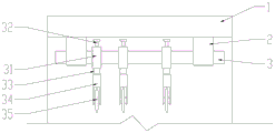
Preferably, cutting mechanism includes a plurality of square sliding blocks, a plurality of connection drum, and is a plurality of square sliding block all is located between two first fixed blocks, and is a plurality of square sliding block all overlaps establish on first axostylus axostyle and with first axostylus axostyle sliding connection, the bottom surface of square sliding block has set firmly the threaded rod, the threaded rod lower extreme is located and connects the drum and with connection drum threaded connection, install cutting blade on connecting the drum, cutting blade rotates with connecting the drum and is connected.
Preferably, the top surface of square sliding block threaded connection has the puller bolt, the lower extreme of puller bolt runs through the top surface of square sliding block and contacts with the first axis pole.
Preferably, the material receiving mechanism comprises two third fixed blocks, a first strip receiving roller, two fourth fixed blocks, a second strip receiving roller, a first transmission belt and a second transmission belt, the two third fixed blocks are fixedly arranged on the right side face of the fixed frame, and two ends of the first strip receiving roller respectively penetrate through the two third fixed blocks and are rotatably connected with the two third fixed blocks; the two fourth fixing blocks are fixedly arranged on the right side surface of the fixing frame, and two ends of the second take-up roll respectively penetrate through the two fourth fixing blocks and are rotatably connected with the two fourth fixing blocks; the second take-up roller is positioned right below the first take-up roller and is connected with the first take-up roller through a first transmission belt; the motor is arranged above the first winding roller and fixedly connected with the right side face of the fixing frame through the connecting block, and a power output shaft of the motor is connected with the first winding roller through a second transmission belt.
Preferably, one of first receipts strip roller serves fixed cover and is equipped with two first belt pulleys, one of second receipts strip roller serves fixed cover and is equipped with the second belt pulley, fixed cover is equipped with the third belt pulley on the power output shaft of motor, two first belt pulley is respectively through first driving belt, second driving belt and second belt pulley, third belt pulley connection.
Preferably, the second feeding mechanism comprises two U-shaped frames, the two U-shaped frames are respectively and fixedly connected with the upper groove wall and the lower groove wall of the discharge groove, a plurality of rollers are sleeved on the transverse part of each U-shaped frame, and the rollers are all rotatably connected with the U-shaped frames; the first feeding mechanism is the same as the second feeding mechanism.
Preferably, dust absorption mechanism includes the air exhauster, the air exhauster sets firmly the top surface at the mount, the one end of the exhaust column of air exhauster runs through the top surface of mount and extends to in the mount, the one end that the exhaust column is located the mount has set firmly the suction hood, the suction hood is towards cutting mechanism.
Preferably, a filter screen is fixedly arranged at one end of the air outlet pipe of the exhaust fan.
The utility model has the advantages that:
1. the utility model discloses set up first axostylus axostyle, square sliding block, a plurality of square sliding blocks can slide on first axostylus axostyle to the drum is connected in the drive, cutting blade controls on first axostylus axostyle and moves, thereby has changed the interval between the adjacent cutting blade, thereby realizes that control divides the cutting width of strip, promotes and divides the holistic suitability of strip machine.
2. The utility model discloses the setting is through setting up the threaded rod, connecting drum, cutting blade, driving roller, and the thickness of cutting the non-woven fabrics as required comes the swivelling joint drum, makes to connect the drum along the threaded rod upwards or move down to adjust the distance between cutting blade and the driving roller, avoid the in-process of non-woven fabrics cutting to take place not hard up, and influence the precision of cutting.
3. The utility model discloses the setting is through setting up air exhauster, exhaust column, and when this device moves, through starting the air exhauster, the scrap of cloth or the dust that make the air exhauster will cut the non-woven fabrics and produce absorb to avoid the non-woven fabrics of cutting to glue scrap of cloth or dust, help protecting the quality of cutting back non-woven fabrics, and the air exhauster is at the during operation, can accelerate near cutting mechanism's air flow, thereby accelerated cutting blade's heat dissipation, avoid cutting blade high temperature and damage the non-woven fabrics.
4. The utility model discloses a set up first receipts strip roller, second receipts strip roller, motor, through the starter motor, it is rotatory to make electronic first receipts strip roller, second receipts strip roller of driving through first driving belt, second driving belt to make first receipts strip roller, second receipts strip roller collect the non-woven fabrics of cutting completion simultaneously, accelerated the speed of collecting, promoted production efficiency.
Drawings
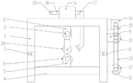
Fig. 1 is a schematic view of the structure of the present invention;
fig. 2 is a right side view of the cutting mechanism of the present invention;
fig. 3 is a right side view of the material receiving mechanism of the present invention;
fig. 4 is an enlarged schematic view of a portion a of fig. 3 according to the present invention.
Reference numerals: 1. a fixed mount; 2. a first fixed block; 3. a first shaft lever; 4. a carrier plate; 5. a second fixed block; 6. a driving roller; 7. a feed chute; 8. a discharge chute; 9. a third fixed block; 10. a first take-up roll; 11. a fourth fixed block; 12. a second take-up roll; 13. a first drive belt; 14. a motor; 15. a second drive belt; 16. an exhaust fan; 17. an exhaust pipe; 18. an air outlet pipe; 19. a filter screen; 25. a first pulley; 26. a second pulley; 27. a third belt pulley; 28. a U-shaped frame; 29. a roller; 31. a square slider; 32. jacking the bolt; 33. a threaded rod; 34. a connecting cylinder; 35. and (4) cutting the blade.
Detailed Description
In order to make the technical means, the creation features, the achievement purposes and the functions of the present invention easy to understand, the present invention will be further explained below with reference to the following embodiments and the accompanying drawings, but the following embodiments are only the preferred embodiments of the present invention, and not all embodiments are included. Based on the embodiments in the implementation, other embodiments obtained by those skilled in the art without any creative work belong to the protection scope of the present invention.
Specific embodiments of the present invention will be described below with reference to the accompanying drawings.
Examples
As shown in fig. 1-4, a non-woven fabric slitting machine with an ordered discharging device comprises a fixed frame 1, two first fixed blocks 2 are fixedly arranged on the inner top surface of the fixed frame 1, a first shaft rod 3 is arranged on the fixed frame 1, the first shaft rod 3 penetrates through the two first fixed blocks 2 and is fixedly connected with the two first fixed blocks 2, and a plurality of cutting mechanisms are arranged on the first shaft rod 3; a bearing plate 4 is fixedly arranged on the fixed frame 1, two second fixed blocks 5 are fixedly arranged on the top surface of the bearing plate 4, a driving roller 6 is arranged between the two second fixed blocks 5, and two ends of the driving roller 6 respectively penetrate through the two second fixed blocks 5 and are rotatably connected with the two second fixed blocks 5; the driving roller 6 is positioned right below the cutting mechanism; a feeding groove 7 is formed in the left side surface of the fixing frame 1, a first feeding mechanism is arranged in the feeding groove 7, a discharging groove 8 is formed in the right side surface of the fixing frame 1, and a second feeding mechanism is arranged in the discharging groove 8; a material receiving mechanism is arranged on the right side surface of the fixed frame 1; the dust collection mechanism is arranged on the top surface of the fixing frame 1, the cutting mechanism comprises a plurality of square sliding blocks 31 and a plurality of connecting cylinders 34, the square sliding blocks 31 are located between the two first fixing blocks 2, the square sliding blocks 31 are sleeved on the first shaft rods 3 and are in sliding connection with the first shaft rods 3, threaded rods 33 are fixedly arranged on the bottom surfaces of the square sliding blocks 31, the lower ends of the threaded rods 33 are located in the connecting cylinders 34 and are in threaded connection with the connecting cylinders 34, cutting blades 35 are mounted on the connecting cylinders 34, the cutting blades 35 are in rotating connection with the connecting cylinders 34, tightening bolts 32 are in threaded connection with the top surfaces of the square sliding blocks 31, the lower ends of the tightening bolts 32 penetrate through the top surfaces of the square sliding blocks 31 and are in contact with the first shaft rods 3, the material receiving mechanism comprises two third fixing blocks 9, a first strip receiving roller 10, two fourth fixing blocks 11, a second strip receiving roller 12, a first transmission belt 13, The two third fixing blocks 9 are fixedly arranged on the right side surface of the fixing frame 1, and two ends of the first strip collecting roller 10 penetrate through the two third fixing blocks 9 respectively and are rotatably connected with the two third fixing blocks 9; the two fourth fixing blocks 11 are fixedly arranged on the right side surface of the fixing frame 1, and two ends of the second take-up roll 12 penetrate through the two fourth fixing blocks 11 respectively and are rotatably connected with the two fourth fixing blocks 11; the second take-up roller 12 is positioned right below the first take-up roller 10, and the second take-up roller 12 is connected with the first take-up roller 10 through a first transmission belt 13; a motor 14 is arranged above the first strip receiving roller 10, the motor 14 is fixedly connected with the right side face of the fixed frame 1 through a connecting block, a power output shaft of the motor 14 is connected with the first strip receiving roller 10 through a second transmission belt 15, one end of the first strip receiving roller 10 is fixedly sleeved with two first belt pulleys 25, one end of the second strip receiving roller 12 is fixedly sleeved with a second belt pulley 26, a power output shaft of the motor 14 is fixedly sleeved with a third belt pulley 27, the two first belt pulleys 25 are respectively connected with the second belt pulley 26 and the third belt pulley 27 through the first transmission belt 13 and the second transmission belt 15, the second feeding mechanism comprises two U-shaped frames 28, the two U-shaped frames 28 are respectively and fixedly connected with the upper groove wall and the lower groove wall of the discharge groove 8, a plurality of idler wheels 29 are sleeved on the transverse part of the U-shaped frames 28, and the plurality of idler wheels 29 are rotatably connected with the U-shaped frames 28; the first feeding mechanism is the same as the second feeding mechanism, the dust collection mechanism comprises an exhaust fan 16, the exhaust fan 16 is fixedly arranged on the top surface of the fixing frame 1, one end of an exhaust pipe 17 of the exhaust fan 16 penetrates through the top surface of the fixing frame 1 and extends into the fixing frame 1, a dust hood is fixedly arranged at one end, located in the fixing frame 1, of the exhaust pipe 17, the dust hood faces the cutting mechanism, and a filter screen 19 is fixedly arranged at one end of an air outlet pipe 18 of the exhaust fan 16.
The working principle is as follows: the width of the non-woven fabric after being split is obtained as required, the puller bolt 32 is separated from the first shaft rod 3 by rotating the puller bolt 32, the square sliding block 31 can slide on the first shaft rod 3, the positions of the cutting blades 35 are adjusted, and after the positions of the cutting blades 35 are adjusted, the puller bolt 32 is in contact with the first shaft rod 3 by screwing the puller bolt 32, so that the square sliding block 31 is fixed on the first shaft rod 3; according to the thickness of the non-woven fabric to be cut, the connecting cylinder 34 is rotated, the connecting cylinder 34 moves upwards or downwards along the threaded rod 33, the connecting cylinder 34 drives the cutting blade 35 to move when moving, and therefore the distance between the cutting blade 35 and the driving roller 6 is adjusted, and the problem that the non-woven fabric is loosened in the cutting process to affect the cutting precision is avoided.
The cut non-woven fabric is respectively wound on the first strip collecting roller 10 and the second strip collecting roller 12, the motor 14 is started, the power output shaft of the motor 14 drives the third belt pulley 27 to rotate, the first strip collecting roller 10 is driven to rotate through the second transmission belt 15, and the second strip collecting roller 12 is driven to rotate through the first transmission belt 13, so that the cut non-woven fabric is collected by the first strip collecting roller 10 and the second strip collecting roller 12 at the same time, the collecting speed is increased, and the production efficiency is improved;
when the first strip receiving roller 10 and the second strip receiving roller 12 rotate, uncut non-woven fabric can be pulled to move rightwards, so that the non-woven fabric passes through a gap between the cutting mechanism and the driving roller 6, the cutting mechanism cuts the non-woven fabric, and the non-woven fabric after cutting can pass through the second feeding mechanism in the discharge chute 8 and is respectively wound on the first strip receiving roller 10 and the second strip receiving roller 12.
When this device moves, through starting air exhauster 16, the cloth bits or the dust that make air exhauster 16's exhaust column 17 will cut the non-woven fabrics production absorb to avoid the non-woven fabrics of cutting to glue cloth bits or dust, help protecting the quality of cutting back non-woven fabrics, and air exhauster 16 is at the during operation, can accelerate near cutting mechanism's air flow, thereby accelerated cutting blade 35's heat dissipation, avoid cutting blade 35 high temperature and damage the non-woven fabrics.
The foregoing shows and describes the general principles, essential features, and advantages of the invention. It should be understood by those skilled in the art that the present invention is not limited by the above embodiments, and the description in the above embodiments and the description is only preferred examples of the present invention, and is not intended to limit the present invention, and that the present invention can have various changes and modifications without departing from the spirit and scope of the present invention, and these changes and modifications all fall into the scope of the claimed invention. The scope of the invention is defined by the appended claims and equivalents thereof.
Claims (8)
1. The utility model provides a non-woven fabrics divides strip machine with orderly discharge apparatus, includes mount (1), its characterized in that: two first fixing blocks (2) are fixedly arranged on the inner top surface of the fixing frame (1), a first shaft rod (3) is arranged on the fixing frame (1), the first shaft rod (3) penetrates through the two first fixing blocks (2) and is fixedly connected with the two first fixing blocks (2), and a plurality of cutting mechanisms are arranged on the first shaft rod (3); a bearing plate (4) is fixedly arranged on the fixing frame (1), two second fixing blocks (5) are fixedly arranged on the top surface of the bearing plate (4), a transmission roller (6) is arranged between the two second fixing blocks (5), and two ends of the transmission roller (6) respectively penetrate through the two second fixing blocks (5) and are rotatably connected with the two second fixing blocks (5); the transmission roller (6) is positioned right below the cutting mechanism; a feeding groove (7) is formed in the left side surface of the fixing frame (1), a first feeding mechanism is arranged in the feeding groove (7), a discharging groove (8) is formed in the right side surface of the fixing frame (1), and a second feeding mechanism is arranged in the discharging groove (8); a material receiving mechanism is arranged on the right side surface of the fixing frame (1); and a dust suction mechanism is arranged on the top surface of the fixing frame (1).
2. The non-woven fabric slitting machine with the ordered discharging device according to claim 1, is characterized in that: cutting mechanism includes a plurality of square sliding blocks (31), a plurality of connection drum (34), and is a plurality of square sliding block (31) all are located between two first fixed blocks (2), and are a plurality of square sliding block (31) all overlap establish on first axostylus axostyle (3) and with first axostylus axostyle (3) sliding connection, the bottom surface of square sliding block (31) has set firmly threaded rod (33), threaded rod (33) lower extreme be located connect drum (34) and with be connected drum (34) threaded connection, connect and install cutting blade (35) on drum (34), cutting blade (35) with be connected drum (34) and rotate and be connected.
3. The non-woven fabric slitting machine with the ordered discharging device according to claim 2, is characterized in that: the top surface threaded connection of square sliding block (31) has puller bolt (32), the lower extreme of puller bolt (32) runs through the top surface of square sliding block (31) and contacts with first axostylus axostyle (3).
4. The non-woven fabric slitting machine with the ordered discharging device according to claim 1, is characterized in that: the material receiving mechanism comprises two third fixing blocks (9), a first strip receiving roller (10), two fourth fixing blocks (11), a second strip receiving roller (12), a first transmission belt (13) and a second transmission belt (15), the two third fixing blocks (9) are fixedly arranged on the right side face of the fixing frame (1), and two ends of the first strip receiving roller (10) penetrate through the two third fixing blocks (9) respectively and are rotatably connected with the two third fixing blocks (9); the two fourth fixing blocks (11) are fixedly arranged on the right side face of the fixing frame (1), and two ends of the second strip winding roller (12) penetrate through the two fourth fixing blocks (11) respectively and are rotatably connected with the two fourth fixing blocks (11); the second take-up roller (12) is positioned under the first take-up roller (10), and the second take-up roller (12) is connected with the first take-up roller (10) through a first transmission belt (13); a motor (14) is arranged above the first winding roller (10), the motor (14) is fixedly connected with the right side face of the fixing frame (1) through a connecting block, and a power output shaft of the motor (14) is connected with the first winding roller (10) through a second transmission belt (15).
5. The non-woven fabric slitting machine with the ordered discharging device according to claim 4, is characterized in that: one of first receipts strip roller (10) is served and is fixed the cover and be equipped with two first belt pulley (25), one of second receipts strip roller (12) is served and is fixed the cover and be equipped with second belt pulley (26), fixed cover is equipped with third belt pulley (27), two on the power output shaft of motor (14) first belt pulley (25) are connected with second belt pulley (26), third belt pulley (27) through first driving belt (13), second driving belt (15) respectively.
6. The non-woven fabric slitting machine with the ordered discharging device according to claim 1, is characterized in that: the second feeding mechanism comprises two U-shaped frames (28), the two U-shaped frames (28) are respectively and fixedly connected with the upper groove wall and the lower groove wall of the discharge groove (8), a plurality of rollers (29) are sleeved on the transverse part of each U-shaped frame (28), and the rollers (29) are all rotatably connected with the U-shaped frames (28); the first feeding mechanism is the same as the second feeding mechanism.
7. The non-woven fabric slitting machine with the ordered discharging device according to claim 1, is characterized in that: dust absorption mechanism includes air exhauster (16), air exhauster (16) set firmly the top surface at mount (1), the top surface of mount (1) is run through and extend to in mount (1) to the one end of the exhaust column (17) of air exhauster (16), the one end that exhaust column (17) are located mount (1) has set firmly the suction hood, the suction hood is towards cutting mechanism.
8. The non-woven fabric slitting machine with the ordered discharging device according to claim 7, is characterized in that: and a filter screen (19) is fixedly arranged at one end of an air outlet pipe (18) of the exhaust fan (16).
Priority Applications (1)
| Application Number | Priority Date | Filing Date | Title |
|---|---|---|---|
| CN202022362244.8U CN215248590U (en) | 2020-10-21 | 2020-10-21 | Non-woven fabric slitting machine with ordered discharging device |
Applications Claiming Priority (1)
| Application Number | Priority Date | Filing Date | Title |
|---|---|---|---|
| CN202022362244.8U CN215248590U (en) | 2020-10-21 | 2020-10-21 | Non-woven fabric slitting machine with ordered discharging device |
Publications (1)
| Publication Number | Publication Date |
|---|---|
| CN215248590U true CN215248590U (en) | 2021-12-21 |
Family
ID=79451498
Family Applications (1)
| Application Number | Title | Priority Date | Filing Date |
|---|---|---|---|
| CN202022362244.8U Active CN215248590U (en) | 2020-10-21 | 2020-10-21 | Non-woven fabric slitting machine with ordered discharging device |
Country Status (1)
| Country | Link |
|---|---|
| CN (1) | CN215248590U (en) |
-
2020
- 2020-10-21 CN CN202022362244.8U patent/CN215248590U/en active Active
Similar Documents
| Publication | Publication Date | Title |
|---|---|---|
| CN210439043U (en) | A cutter for chemical fiber cloth production | |
| CN109733938B (en) | Level high-efficient surface fabric cutting equipment of roll-up | |
| CN215248590U (en) | Non-woven fabric slitting machine with ordered discharging device | |
| CN112482006B (en) | Intelligent new spinning material cutting device for spinning | |
| CN110144721B (en) | Multifunctional slitting machine for producing dust-free cloth | |
| CN109440442B (en) | Full-automatic corrugated zigzag cloth cutting machine | |
| CN112173824A (en) | Weaving cloth cuts coiling mechanism | |
| CN213415749U (en) | Rewinding and splitting machine with automatic film slitter edge collection function | |
| CN213947013U (en) | Machine capable of efficiently cutting gypsum blocks without dust | |
| CN213170633U (en) | High-speed railway soundproof cotton production is with cutting to beat package | |
| CN210791341U (en) | Plate cutting machine capable of cutting plates with different thicknesses | |
| CN209831762U (en) | Automatic edge trimmer | |
| CN109969840B (en) | Automatic spreading machine | |
| CN113291910A (en) | Slitting machine and slitting method for producing high-molecular waterproof coiled material | |
| CN219945233U (en) | Cutting and polishing device for pultruded panels | |
| CN218861207U (en) | Novel high-speed strip machine that divides of non-woven fabrics | |
| CN215797383U (en) | Winding and cutting device for circular knitting machine | |
| CN220813188U (en) | Curtain processing fabric cutting device | |
| CN212170533U (en) | Cutting device is used in heat insulating strip production | |
| CN219385468U (en) | Multifunctional spinning equipment | |
| CN217869684U (en) | Automatic edge cutting equipment for cloth for clothing production | |
| CN214694849U (en) | Edge trimmer is used in non-woven fabrics processing of convenient adjustment | |
| CN210177251U (en) | Fabric cutting and collecting device and full-automatic fabric cutting and sewing system | |
| CN217777142U (en) | Polishing pad cutting device capable of cleaning dust | |
| CN213866996U (en) | Slitting device for production of sanitary masks |
Legal Events
| Date | Code | Title | Description |
|---|---|---|---|
| GR01 | Patent grant | ||
| GR01 | Patent grant |