CN215238178U - Nonrust steel pipe cutting equipment - Google Patents
Nonrust steel pipe cutting equipment Download PDFInfo
- Publication number
- CN215238178U CN215238178U CN202023207270.XU CN202023207270U CN215238178U CN 215238178 U CN215238178 U CN 215238178U CN 202023207270 U CN202023207270 U CN 202023207270U CN 215238178 U CN215238178 U CN 215238178U
- Authority
- CN
- China
- Prior art keywords
- fixedly connected
- steel pipe
- wall
- pipe cutting
- shell
- Prior art date
- Legal status (The legal status is an assumption and is not a legal conclusion. Google has not performed a legal analysis and makes no representation as to the accuracy of the status listed.)
- Active
Links
Images
Landscapes
- Sawing (AREA)
Abstract
The utility model discloses a nonrust steel pipe cutting equipment, which comprises a housin, the bottom fixedly connected with framework of casing, the bottom swing joint of framework inner wall has the slide bar, the top fixedly connected with of slide bar collects the frame, the bottom of casing is provided with the funnel, shells inner wall's bottom fixedly connected with protection casing, the inner wall fixedly connected with electro-magnet of protection casing, the first anchor clamps of the equal fixedly connected with in both sides of shells inner wall bottom, the equal fixedly connected with connecting plate in top of shells inner wall both sides, the first cylinder of bottom fixedly connected with of connecting plate. The utility model discloses possess the advantage of environmental protection, solved current nonrust steel pipe cutting equipment at the in-process that uses, be not convenient for collect waste material and smoke and dust that nonrust steel pipe cutting produced, cause the processing environment to receive the pollution easily, influence staff's healthy, reduced the problem of nonrust steel pipe cutting practicality.
Description
Technical Field
The utility model relates to a nonrust steel pipe technical field specifically is a nonrust steel pipe cutting equipment.
Background
The stainless steel pipe is a hollow long-strip round steel material, and is mainly widely used for industrial conveying pipelines and mechanical structural components of petroleum, chemical industry, medical treatment, food, light industry, mechanical instruments and the like, and is also widely used for manufacturing mechanical parts and engineering structures and is also commonly used as furniture kitchenware and the like because the stainless steel pipe has the same bending strength and torsional strength, and is divided into a common carbon steel pipe, a high-quality carbon steel pipe, an alloy structural pipe, an alloy steel pipe, a bearing steel pipe, a stainless steel pipe, a bimetal composite pipe, a coating layer pipe and the like for saving precious metals and meeting special requirements according to the material quality.
The waste material and the smoke and dust that present nonrust steel pipe cutting equipment produced are not convenient for collect nonrust steel pipe cutting at the in-process that uses, cause the processing environment to receive the pollution easily, influence that the staff's is healthy, have reduced the practicality of nonrust steel pipe cutting.
SUMMERY OF THE UTILITY MODEL
An object of the utility model is to provide a nonrust steel pipe cutting equipment possesses the advantage of environmental protection, has solved current nonrust steel pipe cutting equipment at the in-process that uses, is not convenient for collect the waste material and the smoke and dust that nonrust steel pipe cutting produced, causes the processing environment to receive the pollution easily, influences staff's healthy, has reduced the problem of nonrust steel pipe cutting practicality.
In order to achieve the above object, the utility model provides a following technical scheme: a stainless steel pipe cutting device comprises a shell, wherein a frame body is fixedly connected to the bottom of the shell, a sliding rod is movably connected to the bottom of the inner wall of the frame body, a collecting frame is fixedly connected to the top of the sliding rod, a funnel is arranged at the bottom of the shell, a protective cover is fixedly connected to the bottom of the inner wall of the shell, an electromagnet is fixedly connected to the inner wall of the protective cover, first clamps are fixedly connected to two sides of the bottom of the inner wall of the shell, connecting plates are fixedly connected to the tops of two sides of the inner wall of the shell, a first air cylinder is fixedly connected to the bottom of each connecting plate, a second clamp is fixedly connected to the bottom of each first air cylinder, second air cylinders are fixedly connected to two sides of the top of the inner wall of the shell, a fixing plate is fixedly connected to the bottom of each second air cylinder, a motor is fixedly connected to the left side of the bottom of each fixing plate, and a cutting blade is fixedly connected to an output shaft of each motor, the utility model discloses a dust collection device, including fixed plate, dust hood, hose, air-out end of fan, filter box, right side fixedly connected with dust hood of fixed plate bottom, the top intercommunication of dust hood has the hose, the top fixedly connected with fan of casing, the one end that the dust hood was kept away from to the hose communicates with the air inlet end of fan, the left side fixedly connected with rose box at casing top, the air-out end of fan runs through to the inner chamber of rose box, the left side fixedly connected with active carbon air filter core of rose box inner chamber, the bottom fixedly connected with mount of rose box inner chamber, the right side fixedly connected with of mount filters the sack, the air-out end of fan communicates with the right-hand member of filtering the sack.
Preferably, the bottom of the inner wall of the frame body is provided with a sliding groove, and the surface of the sliding rod is movably connected with the inner wall of the sliding groove.
Preferably, the front surface of the collecting frame is fixedly connected with a handle, and the collecting frame is positioned at the bottom of the funnel.
Preferably, four corners of the bottom of the shell are fixedly connected with supporting legs, and one side opposite to the supporting legs is fixedly connected with a reinforcing rod.
Preferably, one side of the first clamp opposite to the second clamp is fixedly connected with an anti-slip layer, and one side of the anti-slip layer opposite to the anti-slip layer is provided with anti-slip grains.
Preferably, the left side of the filter box is provided with an air outlet, and the front side of the filter box is fixedly provided with a sealing door.
Preferably, the right side fixed mounting of casing has the controller, and the output of controller respectively with the input electric connection of first cylinder, second cylinder, motor and fan.
Compared with the prior art, the beneficial effects of the utility model are as follows:
1. the utility model discloses a suction hood, funnel, slide bar, framework, collection frame, electro-magnet, protection casing, rose box, second cylinder, fan, hose, fixed plate, active carbon air filter, mount and the cooperation of filtering the sack use, solved current nonrust steel pipe cutting equipment and at the in-process that uses, be not convenient for collect waste material and smoke and dust that the nonrust steel pipe cutting produced, cause the processing environment to receive the pollution easily, influence staff's healthy, reduced the problem of nonrust steel pipe cutting practicality.
2. The utility model discloses a cooperation of protection casing and electro-magnet is used, can be convenient for adsorb the sweeps that the nonrust steel pipe of cutting produced, through setting up the funnel, can be convenient for collect the sweeps, collect the frame through setting up, can be convenient for store the sweeps, use through the cooperation of framework and slide bar, can be convenient for take out and collect the frame, through first anchor clamps, the cooperation of second anchor clamps and first cylinder is used, can be convenient for carry out the centre gripping to nonrust steel pipe fixed, use through the cooperation of motor and cutting piece, can be convenient for cut nonrust steel pipe.
Drawings
FIG. 1 is a schematic structural view of the present invention;
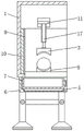
FIG. 2 is a schematic left side view of the present invention;
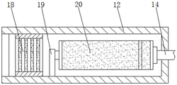
fig. 3 is a schematic view of the front cross section of the filter box of the present invention.
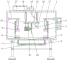
In the figure: the device comprises a shell 1, a dust hood 2, a second clamp 3, a funnel 4, a slide bar 5, a frame 6, a collecting frame 7, a first clamp 8, an electromagnet 9, a protective cover 10, a connecting plate 11, a filter box 12, a second cylinder 13, a fan 14, a hose 15, a fixing plate 16, a first cylinder 17, an active carbon air filter 18, a fixing frame 19, a filter cloth bag 20, a motor 21 and a cutting blade 22.
Detailed Description
The technical solutions in the embodiments of the present invention will be described clearly and completely with reference to the accompanying drawings in the embodiments of the present invention, and it is obvious that the described embodiments are only some embodiments of the present invention, not all embodiments. Based on the embodiments in the present invention, all other embodiments obtained by a person skilled in the art without creative work belong to the protection scope of the present invention.
In the description of the present invention, it should be noted that the terms "upper", "lower", "inner", "outer", "front end", "rear end", "both ends", "one end", "the other end", and the like indicate orientations or positional relationships based on the orientations or positional relationships shown in the drawings, and are only for convenience of description and simplification of description, but do not indicate or imply that the device or element to be referred must have a specific orientation, be constructed in a specific orientation, and be operated, and thus, should not be construed as limiting the present invention. Furthermore, the terms "first" and "second" are used for descriptive purposes only and are not to be construed as indicating or implying relative importance.
In the description of the present invention, it is to be noted that, unless otherwise explicitly specified or limited, the terms "mounted", "provided", "connected", and the like are to be construed broadly, such as "connected", which may be fixedly connected, detachably connected, or integrally connected; can be mechanically or electrically connected; they may be connected directly or indirectly through intervening media, or they may be interconnected between two elements. The specific meaning of the above terms in the present invention can be understood in specific cases to those skilled in the art.
The utility model provides a casing 1, suction hood 2, second anchor clamps 3, funnel 4, slide bar 5, framework 6, collect frame 7, first anchor clamps 8, electro-magnet 9, protection casing 10, connecting plate 11, rose box 12, second cylinder 13, fan 14, hose 15, fixed plate 16, first cylinder 17, active carbon air filter 18, mount 19, filter cloth bag 20, parts such as motor 21 and cutting piece 22 are general standard or the parts that technical personnel in the field know, its structure and principle all can learn through the technical manual or learn through conventional experimental method for technical personnel in the field.
Referring to fig. 1-3, a stainless steel tube cutting device comprises a housing 1, wherein four corners of the bottom of the housing 1 are fixedly connected with supporting legs, and one side opposite to the supporting legs is fixedly connected with a reinforcing rod, the bottom of the housing 1 is fixedly connected with a frame body 6, the bottom of the inner wall of the frame body 6 is movably connected with a slide bar 5, a collecting frame 7 can be conveniently taken out by using the frame body 6 and the slide bar 5 in a matching way, the bottom of the inner wall of the frame body 6 is provided with a chute, the surface of the slide bar 5 is movably connected with the inner wall of the chute, the top of the slide bar 5 is fixedly connected with the collecting frame 7, waste scraps can be conveniently stored by arranging the collecting frame 7, the bottom of the housing 1 is provided with a funnel 4, the waste scraps can be conveniently collected by arranging the funnel 4, the front of the collecting frame 7 is fixedly connected with a handle, the collecting frame 7 is positioned at the bottom of the funnel 4, and the bottom of the inner wall of the housing 1 is fixedly connected with a protective cover 10, the inner wall of the protective cover 10 is fixedly connected with an electromagnet 9, the waste scraps generated by cutting the stainless steel pipe can be conveniently adsorbed by using the protective cover 10 and the electromagnet 9 in a matched manner, both sides of the bottom of the inner wall of the shell 1 are fixedly connected with a first clamp 8, both tops of both sides of the inner wall of the shell 1 are fixedly connected with a connecting plate 11, the bottom of the connecting plate 11 is fixedly connected with a first air cylinder 17, the bottom of the first air cylinder 17 is fixedly connected with a second clamp 3, one side of the first clamp 8 opposite to the second clamp 3 is fixedly connected with an anti-skid layer, one side of the anti-skid layer opposite to the anti-skid layer is provided with anti-skid lines, both sides of the top of the inner wall of the shell 1 are fixedly connected with a second air cylinder 13, the stainless steel pipe can be conveniently clamped and fixed by using the first clamp 8, the second clamp 3 and the first air cylinder 17 in a matched manner, the bottom of the second air cylinder 13 is fixedly connected with a fixing plate 16, the left side of the bottom of the fixed plate 16 is fixedly connected with a motor 21, an output shaft of the motor 21 is fixedly connected with a cutting sheet 22, the stainless steel pipe can be conveniently cut by matching the motor 21 and the cutting sheet 22, the right side of the bottom of the fixed plate 16 is fixedly connected with a dust hood 2, the top of the dust hood 2 is communicated with a hose 15, the top of the shell 1 is fixedly connected with a fan 14, one end, away from the dust hood 2, of the hose 15 is communicated with an air inlet end of the fan 14, the left side of the top of the shell 1 is fixedly connected with a filter box 12, the left side of the filter box 12 is provided with an air outlet hole, the front of the filter box 12 is fixedly provided with a sealing door, the air outlet end of the fan 14 penetrates through to an inner cavity of the filter box 12, the left side of the inner cavity of the filter box 12 is fixedly connected with an activated carbon air filter element 18, the bottom of the inner cavity of the filter box 12 is fixedly connected with a fixing frame 19, and the right side of the fixing frame 19 is fixedly connected with a filter cloth bag 20, air-out end and the right-hand member intercommunication that filters sack 20 of fan 14, the right side fixed mounting of casing 1 has the controller, and the output of controller respectively with first cylinder 17, second cylinder 13, the input electric connection of motor 21 and fan 14, through suction hood 2, the funnel 4, slide bar 5, framework 6, collect frame 7, electro-magnet 9, protection casing 10, rose box 12, second cylinder 13, fan 14, hose 15, fixed plate 16, active carbon air filter 18, mount 19 and the cooperation of filtering sack 20 are used, the in-process of having solved current stainless steel pipe cutting equipment using, be not convenient for collect waste material and smoke and dust that the stainless steel pipe cutting produced, cause the processing environment to receive the pollution easily, influence staff's healthy, the problem of stainless steel pipe cutting practicality has been reduced.
When the stainless steel pipe cutting machine is used, a stainless steel pipe is placed in a first clamp 8, a first air cylinder 17 drives a second clamp 3 to move downwards, the stainless steel pipe is clamped and fixed by the first clamp 8 and the second clamp 3, a fixing plate 16 is driven by a second air cylinder 13 to move downwards, the fixing plate 16 drives a motor 21 to move downwards, an output shaft of the motor 21 drives a cutting piece 22 to cut the stainless steel pipe, a fan 14 collects smoke dust generated by cutting through a hose 15 and a dust hood 2 and discharges the smoke dust into a filter box 12, the smoke dust enters a filter cloth bag 20, the filter cloth bag 20 filters larger particles in the smoke dust, the filtered air is discharged into an active carbon air filter element 18, the active carbon air filter element 18 filters smaller particles in the smoke dust, an electromagnet 9 adsorbs waste scraps generated by cutting, the electromagnet 9 is powered off after cutting is completed, and the waste scraps on the surface of the electromagnet 9 enter a funnel 4, and discharged into the collection frame 7 for collection.
In summary, the following steps: this nonrust steel pipe cutting equipment, through suction hood 2, funnel 4, slide bar 5, framework 6, collect frame 7, electro-magnet 9, protection casing 10, rose box 12, second cylinder 13, fan 14, hose 15, fixed plate 16, active carbon air filter 18, mount 19 and the cooperation of filtering sack 20 are used, the in-process of current nonrust steel pipe cutting equipment using has been solved, be not convenient for collect waste material and smoke and dust that the nonrust steel pipe cutting produced, cause the processing environment to receive the pollution easily, influence the healthy of staff, the problem of nonrust steel pipe cutting practicality has been reduced.
Although embodiments of the present invention have been shown and described, it will be appreciated by those skilled in the art that changes, modifications, substitutions and alterations can be made in these embodiments without departing from the principles and spirit of the invention, the scope of which is defined in the appended claims and their equivalents.
Claims (7)
1. The utility model provides a nonrust steel pipe cutting equipment, includes casing (1), its characterized in that: the bottom of the shell (1) is fixedly connected with a frame body (6), the bottom of the inner wall of the frame body (6) is movably connected with a sliding rod (5), the top of the sliding rod (5) is fixedly connected with a collecting frame (7), the bottom of the shell (1) is provided with a funnel (4), the bottom of the inner wall of the shell (1) is fixedly connected with a protective cover (10), the inner wall of the protective cover (10) is fixedly connected with an electromagnet (9), the two sides of the bottom of the inner wall of the shell (1) are both fixedly connected with first clamps (8), the tops of the two sides of the inner wall of the shell (1) are both fixedly connected with a connecting plate (11), the bottom of the connecting plate (11) is fixedly connected with a first air cylinder (17), the bottom of the first air cylinder (17) is fixedly connected with a second clamp (3), the two sides of the top of the inner wall of the shell (1) are both fixedly connected with a second air cylinder (13), the bottom fixedly connected with fixed plate (16) of second cylinder (13), the left side fixedly connected with motor (21) of fixed plate (16) bottom, the output shaft fixedly connected with cutting piece (22) of motor (21), the right side fixedly connected with suction hood (2) of fixed plate (16) bottom, the top intercommunication of suction hood (2) has hose (15), the top fixedly connected with fan (14) of casing (1), the one end that suction hood (2) were kept away from in hose (15) communicates with the air inlet end of fan (14), the left side fixedly connected with rose box (12) at casing (1) top, the air-out end of fan (14) runs through to the inner chamber of rose box (12), the left side fixedly connected with active carbon air filter core (18) of rose box (12) inner chamber, the bottom fixedly connected with mount (19) of rose box (12) inner chamber, the right side of the fixed frame (19) is fixedly connected with a filtering cloth bag (20), and the air outlet end of the fan (14) is communicated with the right end of the filtering cloth bag (20).
2. The stainless steel pipe cutting apparatus according to claim 1, wherein: the bottom of the inner wall of the frame body (6) is provided with a sliding groove, and the surface of the sliding rod (5) is movably connected with the inner wall of the sliding groove.
3. The stainless steel pipe cutting apparatus according to claim 1, wherein: the front side of the collecting frame (7) is fixedly connected with a handle, and the collecting frame (7) is positioned at the bottom of the funnel (4).
4. The stainless steel pipe cutting apparatus according to claim 1, wherein: the four corners of the bottom of the shell (1) are fixedly connected with supporting legs, and one side, opposite to the supporting legs, is fixedly connected with a reinforcing rod.
5. The stainless steel pipe cutting apparatus according to claim 1, wherein: the anti-skid layer is fixedly connected to one side, opposite to the second clamp (3), of the first clamp (8), and anti-skid grains are formed in one side, opposite to the anti-skid layer.
6. The stainless steel pipe cutting apparatus according to claim 1, wherein: the left side of the filter box (12) is provided with an air outlet, and the front side of the filter box (12) is fixedly provided with a sealing door.
7. The stainless steel pipe cutting apparatus according to claim 1, wherein: the right side fixed mounting of casing (1) has the controller, and the output of controller respectively with first cylinder (17), second cylinder (13), motor (21) and fan (14) input electric connection.
Priority Applications (1)
| Application Number | Priority Date | Filing Date | Title |
|---|---|---|---|
| CN202023207270.XU CN215238178U (en) | 2020-12-28 | 2020-12-28 | Nonrust steel pipe cutting equipment |
Applications Claiming Priority (1)
| Application Number | Priority Date | Filing Date | Title |
|---|---|---|---|
| CN202023207270.XU CN215238178U (en) | 2020-12-28 | 2020-12-28 | Nonrust steel pipe cutting equipment |
Publications (1)
| Publication Number | Publication Date |
|---|---|
| CN215238178U true CN215238178U (en) | 2021-12-21 |
Family
ID=79488208
Family Applications (1)
| Application Number | Title | Priority Date | Filing Date |
|---|---|---|---|
| CN202023207270.XU Active CN215238178U (en) | 2020-12-28 | 2020-12-28 | Nonrust steel pipe cutting equipment |
Country Status (1)
| Country | Link |
|---|---|
| CN (1) | CN215238178U (en) |
-
2020
- 2020-12-28 CN CN202023207270.XU patent/CN215238178U/en active Active
Similar Documents
| Publication | Publication Date | Title |
|---|---|---|
| CN210649201U (en) | Weld piece fixed-position welding device | |
| CN215238178U (en) | Nonrust steel pipe cutting equipment | |
| CN210412797U (en) | Cutter is used in production of microchannel aluminum flat tube | |
| CN209856007U (en) | Gas filtering device of air compressor | |
| CN216171027U (en) | Environment-friendly safe dust removal and collection device for industrial production workshop | |
| CN210650145U (en) | Product clamping device of crystal grinder | |
| CN210545685U (en) | Improved generation industrial dust collecting equipment | |
| CN209887300U (en) | Aluminum capacitor shell that possesses dust removal function is with cutting grinding device | |
| CN212169763U (en) | Dust removing device for machine tool machining | |
| CN210436296U (en) | Woodworking band sawing machine with dust removal function | |
| CN211027450U (en) | Waste collecting device is used in metal product processing | |
| CN212886467U (en) | Twill cutting device | |
| CN202372366U (en) | Coating acquisition device | |
| CN215091947U (en) | Steel band is link device fast broken | |
| CN214556888U (en) | Environment-friendly aluminum alloy processing equipment | |
| CN214445283U (en) | Environment-friendly grinding machine for machining | |
| CN211940046U (en) | Portable cutting machine sweeps cleaning device | |
| CN212575877U (en) | Gas treatment equipment convenient to dismantle | |
| CN215466129U (en) | Efficient rotary classifying screen for feed production | |
| CN214351679U (en) | Part roughness grinds frock | |
| CN211806497U (en) | Automatic pipe cutting machine equipment for carbon fiber pipes | |
| CN212884057U (en) | Feeding device of packaging and printing machine | |
| CN220113450U (en) | Cutting mechanism for ultrafiltration membrane processing | |
| CN214437616U (en) | Unified collection of steel pipe welding waste gas handles purifier | |
| CN219356992U (en) | Automatic vibrating screen with nut gaskets |
Legal Events
| Date | Code | Title | Description |
|---|---|---|---|
| GR01 | Patent grant | ||
| GR01 | Patent grant |