CN215229418U - Old person's auxiliary seat that stands - Google Patents
Old person's auxiliary seat that stands Download PDFInfo
- Publication number
- CN215229418U CN215229418U CN202121641388.5U CN202121641388U CN215229418U CN 215229418 U CN215229418 U CN 215229418U CN 202121641388 U CN202121641388 U CN 202121641388U CN 215229418 U CN215229418 U CN 215229418U
- Authority
- CN
- China
- Prior art keywords
- seat
- supporting plate
- driving mechanism
- plate
- seat support
- Prior art date
- Legal status (The legal status is an assumption and is not a legal conclusion. Google has not performed a legal analysis and makes no representation as to the accuracy of the status listed.)
- Active
Links
Images


Abstract
The utility model relates to the field of old people auxiliary equipment, and discloses an old people standing auxiliary seat, which comprises a seat support, a support plate, a driving mechanism, a crutch placing cylinder, a pressure trigger switch structure and a controller; the supporting plate is arranged above the seat support, the seat support positioned below the supporting plate is of a hollow structure, and one side of the supporting plate is hinged with one side of the seat support; the driving mechanism is arranged below the supporting plate, the movable end of the driving mechanism is hinged with the supporting plate, and the driving mechanism is used for driving the supporting plate to turn over along the hinged part; the pressure trigger switch structure is arranged at the bottom end inside the crutch placing barrel; the controller is electrically connected with the driving mechanism and the pressure trigger switch structure. This technical scheme can assist the old person to get up, conveniently places the walking stick to the supporting position that the old person can be regarded as to the walking stick when getting up increases the equilibrium that the old person got up, convenient to use and safety.
Description
Technical Field
The utility model relates to an old auxiliary assembly field specifically relates to an old person's auxiliary seat that stands.
Background
The society is gradually aging at present, and the elderly become a focus of attention of the society. More and more empty nesters appear at present, and how to enable the empty nesters to better live alone is a concern of people. Due to muscular atrophy, the legs and feet of the old are not flexible, walking needs to be carried out by using a crutch to ensure the safety of the old, and rising on a chair is more a pressure for the old.
SUMMERY OF THE UTILITY MODEL
The utility model aims at providing an old person's auxiliary seat that stands, this utility model can solve the old person who exists among the prior art and rise from the chair inconvenient problem.
In order to achieve the purpose, the utility model provides an old person standing auxiliary seat, which comprises a seat support, a support plate, a driving mechanism, a crutch placing cylinder, a pressure trigger switch structure and a controller; the supporting plate is arranged above the seat support, the seat support positioned below the supporting plate is of a hollow structure, and one side of the supporting plate is hinged with one side of the seat support; the driving mechanism is arranged below the supporting plate, the movable end of the driving mechanism is hinged with the supporting plate, and the driving mechanism is used for driving the supporting plate to turn along the hinged position; the pressure trigger switch structure is arranged at the bottom end of the inside of the crutch placing barrel and is used for being switched on when the detected pressure is higher than a preset pressure value; the controller is electrically connected with the driving mechanism and the pressure trigger switch structure.
Through the setting of above-mentioned technical scheme, when the old person wants to stand up, press the walking stick of placing in the walking stick places a section of thick bamboo to trigger pressure trigger switch structure sends the signal to the controller, by controller control actuating mechanism lifting backup pad, change from the position of sitting to the appearance of standing to the helping hand old person. This technical scheme can assist the old person to get up, conveniently places the walking stick to the supporting position that the old person can be regarded as to the walking stick when getting up increases the equilibrium that the old person got up, convenient to use and safety.
Furthermore, the pressure trigger switch structure comprises a switch, a spring and a placing plate, wherein one end of the spring is fixedly connected with the inner bottom surface of the crutch placing tube, the placing plate is fixedly connected with the other end of the spring, and the switch is positioned below the placing plate and is electrically connected with the controller;
when the spring is compressed by a preset pressure value, the placing plate can be abutted against the switch.
Furthermore, the driving mechanism comprises a bottom plate, a hydraulic cylinder, a guide rail shaft and a chute, the bottom plate is fixedly connected with the bottom end of the seat support, the hydraulic cylinder is arranged on the bottom plate, the guide rail shaft penetrates through the movable end of the hydraulic cylinder, and the guide rail shaft is perpendicular to the axis of the hydraulic cylinder; the sliding groove is fixedly connected with the bottom surface of the supporting plate, and the guide rail shaft is movably and rotatably arranged in the sliding groove in a penetrating way.
Further, the inner edge of the hollow structure of the seat support is smaller than the outer contour of the support plate.
Furthermore, armrests are arranged on two sides of the seat support.
Furthermore, a through hole is formed in the handrail, and the through hole and the crutch containing barrel are located on the same axis.
Furthermore, a recovery switch is arranged on the armrest and electrically connected with the controller; when the recovery switch is switched on, the driving mechanism drives the supporting plate to turn towards the driving mechanism.
Further, a cushion is sleeved on the supporting plate.
Further, a recess is arranged in the middle of the seat cushion.
Other features and advantages of the present invention will be described in detail in the detailed description which follows.
Drawings
Fig. 1 is a schematic view of a viewing angle of the present invention;
FIG. 2 is a schematic structural view of a crutch placing tube;
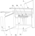
fig. 3 is a schematic structural view of another view angle of the present invention;
fig. 4 is a schematic structural view of the seat support.
Description of the reference numerals
1-a seat support; 2-a support plate; 3-a crutch placing cylinder; 41-a switch; 42-a spring; 43-placing the plate; 51-a base plate; 52-hydraulic cylinder; 53-guide rail shaft; 54-a chute; 6-arm rest; 61-a through hole; 62-a resume switch; 7-cushion; 71-concave.
Detailed Description
The following describes the embodiments of the present invention in detail. It is to be understood that the description of the embodiments herein is for purposes of illustration and explanation only and is not intended to limit the invention.
In the present invention, the use of the terms of orientation such as "upper and lower" in the case where no description is made to the contrary generally means the orientation in the assembled and used state. "inner and outer" refer to the inner and outer contours of the respective component itself.
The utility model provides an old people standing auxiliary seat, as shown in figures 1-4, comprising a seat support 1, a support plate 2, a driving mechanism, a crutch placing tube 3, a pressure trigger switch structure and a controller; the supporting plate 2 is arranged above the seat support 1, the seat support 1 positioned below the supporting plate 2 is of a hollow structure, and one side of the supporting plate 2 is hinged with one side of the seat support 1; the driving mechanism is arranged below the supporting plate 2, the movable end of the driving mechanism is hinged with the supporting plate 2, and the driving mechanism is used for driving the supporting plate 2 to turn along the hinged position; the crutch placing tube 3 is fixedly connected with the seat support 1, and the pressure trigger switch structure is arranged at the bottom end inside the crutch placing tube 3 and is used for being switched on when the detected pressure is higher than a preset pressure value; the controller is electrically connected with the driving mechanism and the pressure trigger switch structure.
Through the setting of above-mentioned technical scheme, when the old person wants to stand up, press the walking stick of placing in a section of thick bamboo 3 at the walking stick to trigger pressure trigger switch structure sends the signal to the controller, by controller control actuating mechanism lifting backup pad 2, change from the position of sitting to the position of standing to the helping hand old person. This technical scheme can assist the old person to get up, conveniently places the walking stick to the supporting position that the old person can be regarded as to the walking stick when getting up increases the equilibrium that the old person got up, convenient to use and safety.
The specific structure of one specific embodiment of the seat support 1 is shown in fig. 4, and includes a stool body and a seat back, wherein the upper surface of the stool body is a hollow structure, which facilitates the connection of the support plate 2 and the driving mechanism. Of course, the seat back may not be included in the seat frame 1.
As a specific embodiment of the pressure trigger switch, preferably, as shown in fig. 2, the pressure trigger switch structure includes a switch 41, a spring 42, and a placing plate 43, one end of the spring 42 is fixedly connected with the inner bottom surface of the crutch placing tube 3, the placing plate 43 is fixedly connected with the other end of the spring 42, the switch 41 is located below the placing plate 43 and is electrically connected with the controller; the switch 41 is a push switch;
when the spring 42 is compressed by a predetermined pressure value, the resting plate 43 can be pressed against the switch 41. The preset pressure value is larger than the gravity of a common crutch in the market. The pressure trigger switch structure does not trigger the switch 41 under the condition that only the crutch is placed, when the force pressing the crutch acts on the spring 42 when the old person gets up, the spring 42 is compressed, the placing plate 43 moves downwards, the switch 41 is contacted and the switch 41 is communicated, so that the pressure trigger switch structure is used as a signal basis for the old person to get up for assisting the body.
As a specific embodiment of the driving mechanism, preferably, the driving mechanism includes a bottom plate 51, a hydraulic cylinder 52, a guide rail shaft 53 and a sliding chute 54, the bottom plate 51 is fixedly connected with the bottom end of the seat support 1, the hydraulic cylinder 52 is disposed on the bottom plate 51, the guide rail shaft 53 is inserted into the movable end of the hydraulic cylinder 52, and the guide rail shaft 53 is perpendicular to the axis of the hydraulic cylinder 52; the sliding groove 54 is fixedly connected with the bottom surface of the supporting plate 2, and the guide rail shaft 53 is movably and relatively rotatably inserted into the sliding groove 54. Through the arrangement of the technical scheme, the support plate 2 can be gradually raised (the included angle between the support plate 2 and the ground is increased) through the extension of the hydraulic cylinder 52, wherein the guide rail shaft 53 can move in the sliding groove 54 to adapt to the circular motion of the support plate 2. In addition, the sliding grooves 54 can increase the strength of the support plate 2, so that the support plate 2 can bear a greater weight.
In order to be able to better support the support plate 2, the inner edge of the hollow structure of the seat support 1 is preferably smaller than the outer contour of the support plate 2.
In order to facilitate the old people to have a space for placing hands when sitting on the chair and increase the comfort of sitting posture, the two sides of the seat support 1 are preferably provided with armrests 6.
In order to further fix the crutch, a through hole 61 is preferably arranged on the armrest 6, and the through hole 61 is arranged on an axis with the crutch placing tube 3.
In order to avoid the situation that the old man is assisted to stand by the device under the involuntary condition because the crutch is unintentionally pressed by other people to cause the supporting plate 2 to lift, a recovery switch 62 is preferably arranged on the armrest 6, and the recovery switch 62 is electrically connected with the controller; when the return switch 62 is turned on, the driving mechanism drives the support plate 2 to turn in the direction of the driving mechanism.
In order to increase the comfort when sitting on the device, the support plate 2 is preferably provided with a seat cushion 7.
In order to increase the supporting force of the vertical direction in the process of lifting the supporting plate 2, the old people can be simultaneously seated to cause the sinking feeling so as to improve the comfort, and under the preferable condition, the middle of the seat cushion 7 is provided with the recess 71.
It is noted that the electrical connection includes a wire connection.
The above detailed description describes the preferred embodiments of the present invention, but the present invention is not limited to the details of the above embodiments, and the technical idea of the present invention can be within the scope of the present invention, and can be right to the technical solution of the present invention, and these simple modifications all belong to the protection scope of the present invention.
It should be noted that the various features described in the above embodiments may be combined in any suitable manner without departing from the scope of the invention. In order to avoid unnecessary repetition, the present invention does not separately describe various possible combinations.
In addition, various embodiments of the present invention can be combined arbitrarily, and the disclosed content should be regarded as the present invention as long as it does not violate the idea of the present invention.
Claims (9)
1. An auxiliary standing seat for old people is characterized by comprising a seat support (1), a support plate (2), a driving mechanism, a crutch placing barrel (3), a pressure trigger switch structure and a controller; the supporting plate (2) is arranged above the seat support (1), the seat support (1) positioned below the supporting plate (2) is of a hollow structure, and one side of the supporting plate (2) is hinged with one side of the seat support (1); the driving mechanism is arranged below the supporting plate (2), the movable end of the driving mechanism is hinged with the supporting plate (2), and the driving mechanism is used for driving the supporting plate (2) to turn along the hinged position; the crutch placing barrel (3) is fixedly connected with the seat support (1), and the pressure trigger switch structure is arranged at the bottom end inside the crutch placing barrel (3) and is used for being switched on when the detected pressure is higher than a preset pressure value; the controller is electrically connected with the driving mechanism and the pressure trigger switch structure.
2. The standing assistance seat for old people as claimed in claim 1, wherein the pressure trigger switch structure comprises a switch (41), a spring (42), and a placing plate (43), one end of the spring (42) is fixedly connected with the inner bottom surface of the crutch placing tube (3), the placing plate (43) is fixedly connected with the other end of the spring (42), the switch (41) is located below the placing plate (43) and is electrically connected with the controller;
the resting plate (43) is capable of abutting against the switch (41) when the spring (42) is compressed by a predetermined pressure value.
3. The old people standing assisting seat as claimed in claim 1, wherein the driving mechanism comprises a bottom plate (51), a hydraulic cylinder (52), a guide rail shaft (53) and a sliding chute (54), the bottom plate (51) is fixedly connected with the bottom end of the seat support (1), the hydraulic cylinder (52) is arranged on the bottom plate (51), the guide rail shaft (53) is arranged at the movable end of the hydraulic cylinder (52) in a penetrating manner, and the guide rail shaft (53) is perpendicular to the axis of the hydraulic cylinder (52); the sliding groove (54) is fixedly connected with the bottom surface of the supporting plate (2), and the guide rail shaft (53) is movably and relatively rotatably arranged in the sliding groove (54) in a penetrating manner.
4. The standing booster seat for elderly people according to claim 1, characterized in that the inner edge of the hollow structure of the seat support (1) is smaller than the outer contour of the support plate (2).
5. The elderly standing assisting seat as claimed in claim 1, wherein armrests (6) are further provided on both sides of the seat support (1).
6. The elderly standing assisting seat as claimed in claim 5, wherein the armrest (6) is provided with a through hole (61), and the through hole (61) is aligned with the crutch placing tube (3).
7. The elderly standing assisting seat as claimed in claim 5, wherein the armrest (6) is provided with a recovery switch (62), and the recovery switch (62) is electrically connected with the controller; when the recovery switch (62) is switched on, the driving mechanism drives the supporting plate (2) to turn over towards the driving mechanism.
8. The standing assisting seat for the elderly as claimed in claim 1, wherein the supporting plate (2) is sleeved with a cushion (7).
9. The elderly standing booster seat as claimed in claim 8, wherein a recess (71) is provided in the middle of the seat cushion (7).
Priority Applications (1)
| Application Number | Priority Date | Filing Date | Title |
|---|---|---|---|
| CN202121641388.5U CN215229418U (en) | 2021-07-19 | 2021-07-19 | Old person's auxiliary seat that stands |
Applications Claiming Priority (1)
| Application Number | Priority Date | Filing Date | Title |
|---|---|---|---|
| CN202121641388.5U CN215229418U (en) | 2021-07-19 | 2021-07-19 | Old person's auxiliary seat that stands |
Publications (1)
| Publication Number | Publication Date |
|---|---|
| CN215229418U true CN215229418U (en) | 2021-12-21 |
Family
ID=79492924
Family Applications (1)
| Application Number | Title | Priority Date | Filing Date |
|---|---|---|---|
| CN202121641388.5U Active CN215229418U (en) | 2021-07-19 | 2021-07-19 | Old person's auxiliary seat that stands |
Country Status (1)
| Country | Link |
|---|---|
| CN (1) | CN215229418U (en) |
-
2021
- 2021-07-19 CN CN202121641388.5U patent/CN215229418U/en active Active
Similar Documents
| Publication | Publication Date | Title |
|---|---|---|
| US10485727B2 (en) | Piston actuated lumbar stimulation device for a chair | |
| CN202198525U (en) | Electric toilet seat rising chair | |
| US10507146B1 (en) | Sitting to standing lift chair | |
| KR102128494B1 (en) | Chair for elderly and disabled | |
| JP2011004925A (en) | Chair | |
| CN210728175U (en) | Multifunctional action auxiliary chair | |
| CN111134561A (en) | Multifunctional toilet power assisting chair | |
| CN211633024U (en) | Multifunctional toilet power assisting chair | |
| KR102150594B1 (en) | Wheelchair | |
| CN215229418U (en) | Old person's auxiliary seat that stands | |
| CN111588297B (en) | Automatic telescopic device and telescopic method for old-people-assisting toilet | |
| JP2606353Y2 (en) | Lift up chair | |
| CN214806119U (en) | Intelligent auxiliary sitting-up wheelchair | |
| CN210095201U (en) | Five-section bed surface lifting type electric bed | |
| CN208741329U (en) | A kind of electric wheelchair | |
| CN112617491A (en) | Seat device is sat to supplementary stand up of intelligence | |
| CN217091193U (en) | Stair-climbing wheelchair with auxiliary rising structure | |
| CN210611600U (en) | Lifting posture adjustable assists cushion of getting up | |
| AU5543986A (en) | Walker | |
| CN212308769U (en) | Leg and foot rest and seat | |
| JP2572943B2 (en) | Standing assistance chair | |
| CN213189324U (en) | Automatic telescopic device for old-person-assisting toilet | |
| CN219042884U (en) | Auxiliary device for getting on/off bed of old people | |
| CN113041046B (en) | Auxiliary standing device | |
| CN216496111U (en) | Novel auxiliary standing wheelchair |
Legal Events
| Date | Code | Title | Description |
|---|---|---|---|
| GR01 | Patent grant | ||
| GR01 | Patent grant |