CN215226921U - Cooking utensil - Google Patents
Cooking utensil Download PDFInfo
- Publication number
- CN215226921U CN215226921U CN202121170957.2U CN202121170957U CN215226921U CN 215226921 U CN215226921 U CN 215226921U CN 202121170957 U CN202121170957 U CN 202121170957U CN 215226921 U CN215226921 U CN 215226921U
- Authority
- CN
- China
- Prior art keywords
- cavity
- air
- cooking
- microwave
- cooking appliance
- Prior art date
- Legal status (The legal status is an assumption and is not a legal conclusion. Google has not performed a legal analysis and makes no representation as to the accuracy of the status listed.)
- Active
Links
Images


Landscapes
- Electric Ovens (AREA)
Abstract
The utility model discloses a cooking utensil, cooking utensil includes: the cooking device comprises a machine body, wherein a cooking cavity with a taking and placing opening at one side is arranged in the machine body, and the wall surface of the cooking cavity is provided with an enamel surface layer; the door body assembly is arranged on the machine body in a turnover mode so as to open and close the taking and placing opening; the air duct assembly is arranged on the machine body and provided with a plurality of air passing channels; the microwave generating assembly is arranged on the machine body. According to the utility model discloses cooking utensil has advantages such as the air volume is big, the radiating effect is good.
Description
Technical Field
The utility model relates to an electrical apparatus makes technical field, particularly, relates to a cooking utensil.
Background
In the related art, the design of the air duct system of the cooking appliance, such as the micro-steaming and baking all-in-one machine, is one of the most central systems of the machine body. If the air duct is improperly designed, the temperature of the machine body can be increased, the temperature of the electric control and electric appliance devices can be increased, the stability of the system is reduced, and the service life of the electric control element can be shortened due to the fact that the air duct is set at an excessively high temperature.
SUMMERY OF THE UTILITY MODEL
The utility model discloses aim at solving one of the technical problem that exists among the prior art at least. Therefore, the utility model provides a cooking utensil, this cooking utensil has advantages such as the air volume is big, the radiating effect is good.
To achieve the above object, according to an embodiment of the present invention, a cooking appliance is provided, including: the cooking device comprises a machine body, wherein a cooking cavity with a taking and placing opening at one side is arranged in the machine body, and the wall surface of the cooking cavity is provided with an enamel surface layer; the door body assembly is arranged on the machine body in a turnover mode so as to open and close the taking and placing opening; the air duct assembly is arranged on the machine body and provided with a plurality of air passing channels; the microwave generating assembly is arranged on the machine body.
According to the utility model discloses cooking utensil has advantages such as the air volume is big, the radiating effect is good.
In addition, the cooking utensil according to the above embodiment of the present invention may also have the following additional technical features:
according to some embodiments of the invention, the microwave generating assembly comprises: the microwave shell is provided with a first containing cavity, a second containing cavity, a waveguide cavity and a stirring cavity; the microwave generating device is arranged in the first accommodating cavity and can emit microwaves to the waveguide cavity; the stirring piece is arranged in the stirring cavity; the driving piece is arranged in the second accommodating cavity and is in transmission connection with the stirring piece.
According to some embodiments of the present invention, the waveguide cavity has a vertical section and a horizontal section connected to the lower part of the vertical section, the first holding cavity is located at one side of the waveguide cavity, the transmitting head of the microwave generating device is adapted to be followed the side wall of the vertical section stretches into in the vertical section, the stirring cavity is located below the waveguide cavity, the second holding cavity is located above the horizontal section.
According to some embodiments of the utility model, the axis of rotation of the drive shaft of driving piece extends along vertical direction, second holding chamber with first via hole has between the horizontal segment, the horizontal segment with the stirring has the second via hole between the chamber, the drive shaft passes first via hole with the second via hole with the stirring piece links to each other.
According to the utility model discloses a some embodiments, second via hole department is equipped with the axle sleeve subassembly, the axle sleeve subassembly includes: the first shaft sleeve is sleeved on the outer side of the driving shaft and is a metal shaft sleeve; and the second shaft sleeve is sleeved on the outer side of the first shaft sleeve and is an insulating shaft sleeve.
According to some embodiments of the utility model, the microwave casing is located cook the top in chamber, the waveguide chamber with be equipped with first microwave between the stirring chamber and cross the mouth, the stirring chamber with be equipped with second microwave between the cooking chamber and cross the mouth, first microwave is crossed mouth department and is equipped with first transparent separator, second microwave is crossed mouth department and is equipped with the transparent separator of second.
According to some embodiments of the utility model, cooking utensil is equipped with a plurality of heat dissipation spare of treating, the wind channel subassembly includes: the air duct shell is provided with an air inlet, an air outlet and a plurality of air passing channels corresponding to the heat dissipation pieces, each air passing channel is communicated with the air inlet and the air outlet, and at least one part of each heat dissipation piece is arranged in the corresponding air passing channel.
According to some embodiments of the utility model, door body group spare includes: a panel adapted to shield the access opening; the boss is arranged on one side of the panel, which faces the machine body, and is suitable for extending into the cooking cavity, and the boss is provided with a wave suppression structure.
According to some embodiments of the invention, the panel is provided with an outer glass layer, a middle glass layer and an inner glass layer.
According to some embodiments of the invention, the cooking appliance further comprises an outer casing, the outer casing having a containing cavity, the body fitting in the containing cavity.
According to some embodiments of the utility model, get and put the mouth and be located the front side of fuselage, the fuselage is equipped with control panel, control panel locates the front side of fuselage just is located get the top of putting the mouth.
Additional aspects and advantages of the invention will be set forth in part in the description which follows and, in part, will be obvious from the description, or may be learned by practice of the invention.
Drawings
The above and/or additional aspects and advantages of the present invention will become apparent and readily appreciated from the following description of the embodiments, taken in conjunction with the accompanying drawings of which:
fig. 1 is an exploded view of a cooking appliance according to an embodiment of the present invention.
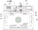
Fig. 2 is a partial structural schematic diagram of a cooking appliance according to an embodiment of the present invention.
Fig. 3 is a partial exploded view of a cooking appliance according to an embodiment of the present invention.
Fig. 4 is a cross-sectional view of a cooking appliance according to an embodiment of the present invention.
Reference numerals: cooking utensil 1, air duct assembly 100, first inlet 1011, second inlet 1012, third inlet 1013, air outlet 102, air inlet cavity 103, first air duct piece 110, first ventilation pipe 111, first air guide piece 112, second ventilation pipe 120, upper half pipe section 121, lower half pipe section 122, third air duct piece 130, air inlet channel 140, driving device 12, controller 13,
A body 200, a cooking cavity 201, a pick-and-place port 202, a control panel 210,
A door body component 300,
The microwave housing 410, the first receiving cavity 401, the second receiving cavity 402, the waveguide cavity 403, the vertical section 4031, the horizontal section 4032, the stirring cavity 404, the microwave generating device 420, the transmitting head 421, the driving member 430, the stirring member 440, the first sleeve 451, the second sleeve 452, the first transparent isolating member 461, the second transparent isolating member 462, the first transparent isolating member 403s,
A right housing 510, a left housing 520, a top housing 530, a bottom housing 540, a back housing 550, a front housing,
Electrically powered water box system 600.
Detailed Description
Reference will now be made in detail to embodiments of the present invention, examples of which are illustrated in the accompanying drawings, wherein like reference numerals refer to the same or similar elements or elements having the same or similar function throughout. The embodiments described below with reference to the drawings are exemplary only for the purpose of explaining the present invention, and should not be construed as limiting the present invention.
A cooking appliance 1 according to an embodiment of the present invention is described below with reference to the accompanying drawings.
As shown in fig. 1 to 4, a cooking appliance 1 according to an embodiment of the present invention may include a body 200, a door assembly 300, an air duct assembly 100, and a microwave generating assembly.
For example, the cooking appliance 1 may be provided with a plurality of heat dissipation members, for example, the cooking appliance 1 is an embedded micro-cooking and baking all-in-one machine, and the heat dissipation members may include one or more of a frequency converter, a magnetron, a condenser tube, a main control PCB, and the like, wherein the magnetron is a part of the microwave generating assembly. The kitchen and electricity integration can enable the style of a kitchen to be integrated, reduce the number of purchased cooking equipment, save cost, reduce floor area, arrange neatly, accord with the simple and elegant aesthetic style of modern people, and meet market requirements.
It should be understood here that the air duct assembly 100 forms an air duct system, which is a heat dissipation system of the machine body, and is mainly used for dissipating heat in the machine body, so that each heat-dissipating member (electronic component to be dissipated) is at a proper temperature, which is very important for the embedded cooking appliance 1.
In some embodiments, a cooking cavity 201 may be provided in the body 200, one side of the cooking cavity 201 is provided with an access opening 202, and the wall of the cooking cavity 201 has an enamel surface. Because the enamel surface treatment technology has the characteristics of no oil stain, easy cleaning and the like, the cooking cavity 201 is convenient to clean, and the aesthetic property of the cooking cavity 201 is convenient to improve. The door assembly 300 is provided in the body 200 and can be turned over with respect to the body 200, so that the door assembly 300 opens and closes the access port 202. Therefore, when the user cooks food, the user can smoothly take and place the food through the taking and placing opening 202, and the operation is convenient. The air duct assembly 100 is disposed on the body 200, and the air duct assembly 100 may be provided with a plurality of air passages. Thus, air in the external environment can enter the air passing channel through the air inlet, and then flows through the air channel and is discharged from the air outlet 102, so that a plurality of air flow passages communicated with the external environment are formed. At least a part of each to-be-cooled element is disposed in the corresponding air passage, so that the air duct assembly 100 can be used to perform corresponding air-cooling heat dissipation on the to-be-cooled element. For example, the frequency converter may be disposed in one of the overfire air channels and the master PCB may be disposed in the other of the overfire air channels. The heat dissipation device has the advantages that the heat dissipation device is convenient to carry out more targeted heat dissipation treatment on the to-be-dissipated parts arranged in the air passing channel, so that the working temperature of each to-be-dissipated part is controlled within a proper range, and the working stability and reliability of each to-be-dissipated part are guaranteed. The microwave generating assembly may be provided on the main body 200, and in particular, the microwave generating assembly may include a microwave case 410 and a magnetron. This allows microwaves to be generated by the microwave generating assembly for microwave heating of the food.
According to the utility model discloses cooking utensil 1, through setting up a plurality of wind passageways of crossing, can be with a plurality of wind passageways of crossing and a plurality of heat dissipation piece of treating corresponding, can set up a plurality of heat dissipation pieces of treating respectively in a plurality of wind passageways of crossing according to actual conditions like this, the total air volume of increase wind channel subassembly 100 of not only being convenient for, improve wind channel subassembly 100's heat dispersion, and can utilize specific wind passageway of crossing to carry out the forced air cooling heat dissipation to the heat dissipation piece of treating that this wind passageway corresponds specially, can have more pertinence ground to the difference treat the heat dissipation piece and cool off the heat dissipation, improve the radiating efficiency and the heat dissipation reliability of treating the heat dissipation piece. Therefore, the temperature of the to-be-cooled part can be prevented from being excessively high, the temperature of the machine body is prevented from being greatly increased, the system stability of the cooking appliance 1 is convenient to improve, and the service lives of the to-be-cooled part and other elements are prolonged.
Therefore, according to the utility model discloses cooking utensil 1 has advantages such as the air volume is big, the radiating effect is good.
A cooking appliance 1 according to an embodiment of the present invention is described below with reference to the accompanying drawings.
In some embodiments of the present invention, as shown in fig. 1 to 4, a cooking appliance 1 according to an embodiment of the present invention may include a body 200, a door assembly 300, an air duct assembly 100, and a microwave generating assembly.
In some embodiments, as shown in fig. 4, the microwave generating assembly may include a microwave housing 410, a microwave generating device 420, a stirring member 440, and a driving member 430, the microwave housing 410 is configured to have a first receiving cavity 401 for receiving the microwave generating device 420, the microwave mixing device comprises a second accommodating cavity 402 for accommodating a driving piece 430, a waveguide cavity 403 for conducting microwaves and a stirring cavity 404 for accommodating a stirring piece 440, at least one part of a microwave generating device 420 is arranged in the first accommodating cavity 401 and can emit microwaves to the waveguide cavity 403, the stirring cavity 404 is connected with the waveguide cavity 403, the stirring piece 440 is arranged in the stirring cavity 404, the stirring piece 440 can stir and disperse the microwaves conveyed to the stirring cavity 404, at least one part of the driving piece 430 is arranged in the second accommodating cavity 402, the driving piece 430 is in transmission connection with the stirring piece 440, and the driving piece 430 can provide driving force for the stirring piece 440 so as to drive the stirring piece 440 to automatically rotate. Therefore, the uniformity and the filling property of the microwave can be improved, the cooking time is shortened, the cooking effect is improved, the microwave generating device 420, the stirring piece 440 and the driving piece 430 are conveniently separated, the protection is convenient to be respectively carried out, the working reliability of the cooking appliance 1 is improved, and the service life of internal parts of the cooking appliance is prolonged.
Alternatively, the stirring member 440 may be a metal stirring sheet.
For example, the first receiving cavity 401 is located at the right side of the waveguide cavity 403, the waveguide cavity 403 is substantially L-shaped, the stirring cavity 404 is located below the waveguide cavity 403, and the second receiving cavity 402 is located in an area defined by the waveguide cavity 403. The main body of the microwave generating device 420 is disposed in the first accommodating chamber 401, and the transmitting head 421 of the microwave generating device 420 extends into the waveguide chamber 403 so as to transmit microwaves to the waveguide chamber 403. Stirring chamber 404 and waveguide chamber 403 link to each other, and the microwave can be carried to stirring chamber 404 from waveguide chamber 403, and stirring member 440 rotationally locates in stirring chamber 404, and stirring member 440 can stir and break up the microwave, makes the microwave output more evenly through reflection or transmission, and stirring chamber 404 and culinary art chamber 201 link to each other, and the microwave after breaking up can smoothly get into culinary art chamber 201 to carry out microwave heating to the food in the culinary art chamber 201. The main body of the driving member 430 is disposed in the second receiving cavity 402, and the driving shaft of the driving member 430 is in transmission connection with the stirring member 440, so as to provide a driving force for the stirring member 440 to make the stirring member 440 automatically rotate. Therefore, the uniformity and the filling property of the microwave can be improved, the cooking time is shortened, the cooking effect is improved, the microwave generating device 420, the stirring piece 440 and the driving piece 430 are conveniently separated, the protection is convenient to be respectively carried out, the working reliability of the cooking appliance 1 is improved, and the service life of internal parts of the cooking appliance is prolonged.
Specifically, as shown in fig. 4, the waveguide cavity 403 may have a vertical segment 4031 and a horizontal segment 4032, i.e., the waveguide cavity 403 may include a vertically extending cavity portion and a horizontally extending cavity portion. The horizontal section 4032 is connected to the lower portion of the vertical section 4031 (in the vertical direction, as shown in fig. 1), the first receiving cavity 401 is disposed on one side of the waveguide cavity 403, the transmitting head 421 of the microwave generating device 420 can extend into the vertical section 4031 from the side wall of the vertical section 4031, the stirring cavity 404 is disposed below the waveguide cavity 403, and the second receiving cavity 402 is disposed above the horizontal section 4032. Therefore, the layout of each cavity in the microwave shell 410 is more compact and reasonable, the occupied space of the microwave shell 410 is reduced, the volume of the cooking cavity 201 is increased as much as possible, the volume utilization rate of the cooking appliance 1 is improved, scattering of microwaves to a certain degree can be realized when the microwaves are transmitted in the waveguide cavity 403, the uniformity and the filling property of microwave output are improved, and the cooking effect is improved.
For example, the waveguide cavity 403 is disposed in the vertical section 4031 and the horizontal section 4032, one end of the horizontal section 4032 is connected to the lower end of the vertical section 4031, and the other end of the horizontal section 4032 extends to the left, the first receiving cavity 401 is located on the right side of the vertical section 4031, the first receiving cavity 401 is separated from the vertical section 4031 by a vertically disposed partition, the partition has a mounting through hole, the transmitting head 421 of the microwave generating device 420 extends into the vertical section 4031 through the mounting through hole, the stirring cavity 404 is located below the waveguide cavity 403, a first microwave through hole is formed between the waveguide cavity 403 and the stirring cavity 404, and microwaves enter the stirring cavity 404 through the first microwave through hole from the waveguide cavity 403. The second receiving cavity 402 is located above the horizontal section 4032, the main body of the driving member 430 is disposed in the second receiving cavity 402, and the driving shaft of the driving member 430 passes through the horizontal section 4032 and is connected to the stirring member 440 in the stirring cavity 404. Therefore, the layout of each cavity in the microwave shell 410 is more compact and reasonable, the occupied space of the microwave shell 410 is reduced, the volume of the cooking cavity 201 is increased as much as possible, scattering of microwaves to a certain degree can be realized when the microwaves are transmitted in the waveguide cavity 403, the output uniformity of the microwaves is improved, and the cooking effect is improved.
Alternatively, the microwave generating device 420 may be a magnetron, which is vertically fixed to the vertical section 4031, and the driving member 430 may be a rotary motor.
More specifically, as shown in fig. 4, the rotation axis of the driving shaft of the driving member 430 is arranged to extend in a vertical direction, a first through hole is formed between the second receiving cavity 402 and the horizontal section 4032, a second through hole is formed between the horizontal section 4032 and the stirring cavity 404, and the driving shaft is adapted to pass through the first through hole and the second through hole to be connected with the stirring member 440. This provides a secure connection between the driving member 430 and the stirring member 440, so that the driving member 430 drives the stirring member 440 to rotate.
Further, as shown in fig. 4, a bushing assembly may be disposed at the second via hole, the bushing assembly may include a first bushing 451 and a second bushing 452, the first bushing 451 is sleeved on an outer side of the driving shaft, the first bushing 451 may be a metal bushing, the second bushing 452 is sleeved on an outer side of the first bushing 451, and the second bushing 452 may be an insulating bushing. Therefore, the rotation friction of the driving shaft can be reduced, and the rotation of the driving shaft is more stable and reliable. Meanwhile, the double-layer shaft sleeve structure is arranged, so that the structural strength of the shaft sleeve assembly can be guaranteed, and the insulating property of the shaft sleeve assembly can be improved.
Alternatively, the second bushing 452 may be a plastic bushing.
Alternatively, as shown in fig. 4, the microwave housing 410 is disposed above the cooking cavity 201, a first microwave through-hole may be disposed between the waveguide cavity 403 and the stirring cavity 404, a second microwave through-hole may be disposed between the stirring cavity 404 and the cooking cavity 201, a first transparent partition 461 may be disposed at the first microwave through-hole, and a second transparent partition 462 may be disposed at the second microwave through-hole. Therefore, microwaves can be smoothly transmitted from the waveguide cavity 403 to the stirring cavity 404 and then from the stirring cavity 404 to the cooking cavity 201, and reliable isolation and protection can be performed between the stirring cavity 404 and the waveguide cavity 403 and between the stirring cavity 404 and the cooking cavity 201, so that each cavity can have a proper working environment, and mutual interference among the cavities is avoided.
For example, first transparent barrier 461 can be the mica sheet, and second transparent barrier 462 can be high temperature borosilicate glass, and high temperature borosilicate glass is applicable to in the isolation of culinary art chamber 201 to the protection microwave takes place the system, and this high temperature borosilicate glass need satisfy and establish the high order in the cavity of culinary art chamber 201, and high temperature borosilicate glass is equipped with the sealing washer all around, is fixed in on the last roof of culinary art chamber 201 by fixed steel ring, and fixed steel ring rivets a plurality ofly all around in order to connect on the cavity roof of culinary art chamber 201.
In some examples, the entire microwave conduction path: high-energy microwaves are generated by a magnetron, and are generated in a vertical section 4031 of a waveguide cavity 403 through an antenna of the magnetron, and then are conducted to a horizontal section 4032 of the waveguide cavity 403, a rotating motor is arranged above the horizontal section 4032 and is connected with a stirring piece 440, a driving shaft of the rotating motor is matched with a metal shaft sleeve and a plastic shaft sleeve, the rotating motor scatters the microwaves through rotation, so that the microwaves are distributed more uniformly in the cooking cavity 201, and the scattered microwaves pass through high-temperature borosilicate glass and irradiate into the cooking cavity 201 to heat the foods by the microwaves. This microwave generation system design is compacter, and the mode of accessible mechanical stirring increases the microwave homogeneity in culinary art chamber 201, and this kind of design culinary art effect is better.
The air duct assembly 100 of the cooking appliance 1 according to the embodiment of the present invention is described below with reference to the accompanying drawings.
In some embodiments, the air duct assembly 100 may include an air duct housing, and the air duct housing may be provided with an air inlet, an air outlet 102, and a plurality of air passages, and the plurality of air passages are respectively disposed corresponding to the plurality of heat dissipation members to be dissipated. Each air passage can be respectively communicated with the air inlet and the air outlet 102, so that air in the external environment can enter the air passage through the air inlet and then flows through the air passage and then is discharged from the air outlet 102, and a plurality of air flow passages communicated with the external environment are formed. At least a portion of each of the heat dissipation members to be cooled is disposed in the corresponding air passage, so that the air duct assembly 100 can be used to cool the heat dissipation members to be cooled in the cooking appliance 1. For example, the frequency converter may be disposed in one of the overfire air channels and the master PCB may be disposed in the other of the overfire air channels. This facilitates a more targeted heat dissipation process of the heat dissipation member to be disposed in the air passage.
According to the utility model discloses cooking utensil 1's wind channel subassembly 100, through setting up a plurality of wind channels of crossing, a plurality of wind channels of crossing are corresponding with a plurality of heat dissipation pieces of treating, can be according to actual conditions with a plurality of heat dissipation pieces of treating set up respectively in a plurality of wind channels of crossing like this, the total air volume of increase wind channel subassembly 100 of not only being convenient for, improve wind channel subassembly 100's heat dispersion, and can utilize specific wind channel of crossing to carry out the forced air cooling heat dissipation to the heat dissipation piece of treating that this wind channel of crossing corresponds specially, can have more pertinence ground to different heat dissipation pieces of treating cool off, improve the radiating efficiency and the heat dissipation reliability of treating the heat dissipation piece. Therefore, the temperature of the to-be-cooled part can be prevented from being excessively high, the temperature of the machine body is prevented from being greatly increased, the system stability of the cooking appliance 1 is convenient to improve, and the service lives of the to-be-cooled part and other elements are prolonged.
Therefore, according to the utility model discloses cooking utensil 1's wind channel subassembly 100 has that the air volume is big, the radiating effect is good, system stability is high and be convenient for prolong advantages such as electrical control element's life-span.
The air duct assembly 100 of the cooking appliance 1 according to the embodiment of the present invention is described below with reference to the accompanying drawings.
In some embodiments, the member to be cooled may include a frequency converter, the duct housing may include the first duct element 110, the air passage may include a first air passage formed in the first duct element 110, and the frequency converter may be adapted to be disposed in the first air passage. Can set up special air channel for the converter like this to carry out the forced air cooling heat dissipation to the converter pertinence ground, because the converter is one of the great device of heat production, can effectively improve the cooling effect of converter like this, reliably control the operating temperature of converter.
For example, the heat dissipation member may include a frequency converter, the air duct housing may include a first air duct element 110, a first air passing channel is formed in the first air duct element 110, and the first air duct element 110 is disposed at an upper portion of the body 200 and is close to a left side edge of the body 200. One end of the first air passing channel is communicated with the air inlet, the other end of the first air passing channel is communicated with the air outlet 102, and the frequency converter is suitable for being arranged in the first air passing channel. Can set up special air channel for the converter like this to carry out the forced air cooling heat dissipation to the converter pertinence ground, because the converter is one of the great device of heat production, can effectively improve the cooling effect of converter like this, reliably control the operating temperature of converter.
Specifically, as shown in fig. 2 and 3, the first air duct 110 may include a first ventilation pipe 111 and a first air guide 112, one end of the first ventilation pipe 111 is adapted to be communicated with the air inlet, the other end of the first air guide is adapted to be connected to one end of the first air guide 112, the other end of the first air guide 112 is adapted to be communicated with the air outlet 102, the frequency converter is adapted to be disposed in the first ventilation pipe 111, and a ventilation area of the first air guide 112 is gradually reduced from one end connected to the first air guide pipe to the other end communicated with the air outlet 102. Therefore, the frequency converter can be conveniently installed and arranged, and the air flow can be guided and smoothly discharged from the air outlet 102.
For example, the first air duct 110 generally extends in the front-rear direction, and the first air duct 110 may include a first ventilation tube 111 and a first air guide 112. The shape of the first duct 111 is adapted to the shape of the frequency converter, for example, the first duct 111 is a rectangular parallelepiped housing. The rear end of the first ventilation pipe 111 is communicated with the air inlet, the front end of the first ventilation pipe 111 is connected with the first air guide 112, and the front end of the first air guide 112 is suitable for being communicated with the air outlet 102. The frequency converter is suitable for being arranged in the first ventilation pipe 111, and the ventilation area of the air guide is gradually reduced from back to front. Therefore, the frequency converter can be conveniently installed and arranged, and the air flow can be guided and smoothly discharged from the air outlet 102.
More specifically, the first air guide 112 is provided in the first ventilation pipe 111 and is detachably configured. This not only facilitates the manufacture of the first air duct member 110, but also facilitates the maintenance and replacement of the components in the first air passage, thereby facilitating the increase in maintainability of the air duct assembly 100.
For example, the rear end of the first air guiding element 112 is engaged with the front end of the first ventilation tube 111.
In some embodiments, as shown in fig. 2, the member to be cooled may include the controller 13, the air passage may include a second air passage, the duct housing may include a second ventilation duct 120, the controller 13 and the second ventilation duct 120 are both disposed in the second air passage, and the second ventilation duct 120 is adapted to blow air toward the controller 13. Can set up special wind passageway for controller 13 like this to pertinence ground carries out the forced air cooling heat dissipation to controller 13, makes its surface temperature rise keep in proper temperature, satisfies its normal operating requirement, prolongs the life-span of automatically controlled components and parts.
For example, the heat sink to be cooled may include the controller 13, and the controller 13 may be a main control PCB. The air passage may include a second air passage extending generally in the fore-aft direction. The air duct housing may include a second ventilation duct 120, the controller 13 is disposed in front of the second ventilation duct 120 in the second ventilation duct, a rear end of the second ventilation duct 120 is communicated with the air inlet, and a front end of the second ventilation duct 120 blows air towards the controller 13. Can set up special wind passageway for controller 13 like this to pertinence ground carries out the forced air cooling heat dissipation to controller 13, makes its surface temperature rise keep in proper temperature, satisfies its normal operating requirement, prolongs the life-span of automatically controlled components and parts. It should be understood here that the second ventilation pipe 120 may be arranged within the second air passage or may form part of the second air passage.
Specifically, as shown in fig. 3, the second ventilation pipe 120 may include an upper half pipe section 121 and a lower half pipe section 122, and the upper half pipe section 121 is configured to be detachably provided to the lower half pipe section 122. This facilitates the installation of the second ventilation duct 120 and facilitates the machining and forming of the second ventilation duct 120.
For example, upper tube half 121 and lower tube half 122 are snap fit.
In some embodiments, the heat dissipation member may include a magnetron, the duct housing may include a third duct member 130, the air passage may include a third air passage formed in the third duct member 130, and the magnetron may be adapted to be disposed in the third air passage. The special air passing channel can be arranged for the magnetron so as to carry out air cooling heat dissipation on the magnetron in a targeted manner, and the magnetron is one of the most main devices for microwave generation and is also one of the heat generating sources, so that the cooling effect of the magnetron can be effectively improved, and the working temperature of the magnetron can be reliably controlled.
For example, the heat dissipation member may include a magnetron, the duct housing may include a third duct member 130, a third air passage may be formed in the third duct member 130, and at least a portion of the magnetron may be adapted to be disposed in the third air passage. For example, the magnetron includes a main body portion and a shell portion, the shell portion is connected with the third air duct member 130 as a whole, so that the flowing air flow can perform air cooling heat dissipation on the magnetron, a special air passage can be provided for the magnetron, so as to perform air cooling heat dissipation on the magnetron in a targeted manner, and since the magnetron is one of the most important devices for microwave generation and is also one of the heat generating sources, the cooling effect of the magnetron can be effectively improved, and the working temperature of the magnetron can be reliably controlled.
In particular, the to-be-cooled member may further include a condensation duct for engine body steam cooling, the condensation duct being adapted to be provided in the third air passing passage and to be disposed downstream of the magnetron in the flow direction of the gas. Therefore, the heat dissipation requirement of the magnetron can be preferentially ensured, and the heat dissipation is carried out on the condensation pipe. Meanwhile, the magnetron and the condenser pipe are arranged in the third air passage, so that the third air passage can become the most important main path in the air passage, and the magnetron and the condenser pipe can be cooled and radiated reliably.
In some embodiments, the air inlet may be located at a rear end of the air duct housing, the air inlet may be located at a front end of the air duct housing, and the plurality of air passages extend in the front-rear direction and are arranged side by side in the left-right direction. Therefore, efficient heat dissipation and cooling can be performed on the heat dissipation member in a targeted manner, the flow resistance of air flow in the air passage can be reduced, and the ventilation quantity and the heat dissipation efficiency are further improved.
For example, the air inlet may be located at a rear end of the air duct housing, the air inlet may be located at a front end of the air duct housing, and the plurality of air passages extend in the front-rear direction and are arranged side by side in the left-right direction. The multiple air passing channels can comprise a first air passing channel, a second air passing channel and a third air passing channel which are sequentially arranged from left to right at intervals. Therefore, efficient heat dissipation and cooling can be performed on the heat dissipation member in a targeted manner, the flow resistance of air flow in the air passage can be reduced, and the ventilation quantity and the heat dissipation efficiency are further improved.
In some embodiments, as shown in FIG. 2, the air duct assembly 100 may further include a drive device 12, the air duct housing may be provided with an air intake chamber 103, the drive device 12 may be disposed within the air intake chamber 103, and the air intake chamber 103 may be adapted to communicate with the air intake and the inlets of the plurality of air passage channels, respectively. Therefore, the air inlet cavity 103 is convenient to communicate with the multiple air passing channels, and the air inlet is convenient to convey air flow to the multiple air passing channels.
Specifically, as shown in fig. 2, the air inlet may include a first inlet 1011 and a second inlet 1012, the first inlet 1011 and the second inlet 1012 may be located at the left and right sides of the rear end of the air duct housing, respectively, and the driving device 12 may be a vortex fan. Therefore, the air inlet area of the air inlet is convenient to increase, the air inlet is convenient to match with the vortex fan, and the driving effect on air flow is improved.
For example, the duct assembly 100 may further include a drive 12, and the drive 12 may be a vortex fan. The air duct housing may be provided with an air inlet chamber 103, the air inlet chamber 103 being located at the rear end of the air duct housing, and the drive means 12 may be located within the air inlet chamber 103. The air inlet may include a first inlet 1011 and a second inlet 1012, the first inlet 1011 and the second inlet 1012 may be respectively located at the left and right sides of the rear end of the air duct housing and respectively communicate with the air inlet chamber 103, and the air inlet chamber 103 respectively communicates with inlets of the plurality of air passing channels. Under the drive of the vortex fan, the air flow can flow to a plurality of air passing channels from the air inlet respectively. Therefore, the air inlet cavity 103 is convenient to communicate with the multiple air passing channels, and the air inlet is convenient to convey air flow to the multiple air passing channels. The air inlet area of the air inlet is convenient to increase, the air inlet is convenient to match with the vortex fan, and the driving effect on air flow is improved.
In other embodiments, as shown in fig. 2, the air inlet can further include a third inlet 1013, the third inlet 1013 can be disposed at the front end of the air duct housing, and the air duct housing can be provided with an air inlet channel 140 that communicates the third inlet 1013 with the air inlet chamber 103. This is convenient for increase the air inlet area of air intake, improves the intake of wind channel subassembly 100. Meanwhile, since only the front end surface of the embedded cooking appliance 1 is exposed to the external environment, the third inlet 1013 is disposed at the front end of the air duct housing, so that the phenomenon that the air intake amounts of the first inlet 1011 and the second inlet 1012 on the side surfaces are insufficient can be compensated, the suction amount of the cold air can be increased, and the cooling efficiency of the air duct assembly 100 can be increased.
For example, the third inlet 1013 is disposed at the upper portion of the front end surface of the air duct housing, the air outlet 102 is disposed at the upper portion of the front end surface of the air duct housing, and the third inlet 1013 and the air outlet 102 are disposed side by side. The duct housing is provided with an air inlet channel 140 communicating the third inlet 1013 with the air inlet chamber 103. This is convenient for increase the air inlet area of air intake, improves the intake of wind channel subassembly 100. Meanwhile, since only the front end surface of the embedded cooking appliance 1 is exposed to the external environment, the third inlet 1013 is disposed at the front end of the air duct housing, so that the phenomenon that the air intake amounts of the first inlet 1011 and the second inlet 1012 on the side surfaces are insufficient can be compensated, the suction amount of the cold air can be increased, and the cooling efficiency of the air duct assembly 100 can be increased.
According to some embodiments of the present invention, the air duct assembly 100 includes 6 air inlets and outlets, including three air inlets and three air outlets 102. The main cyclic paths are: the cool air is introduced from the first inlet 1011 and the second inlet 1012 at the two rear outer sides of the body 200 and the third inlet 1013 at the discreet front face, respectively, and is sucked into the air flow from both sides and blown out from the front side by the vortex fan. The airflow blows to the electrical components to achieve the purpose of heat dissipation. When the vortex fan is driven, the airflow passes through the air guide cover main body at the leftmost side, passes through the first duct 111 outside the inverter, passes through the first air guide 112, and is blown out from the front outlet 102. The leftmost wind channel route is route 1, and the air intake admits air promptly, and air outlet 102 gives vent to anger, and this wind channel route mainly cools off the converter, and the converter is one of the great device of heat production, and wherein first wind guide 112 forms into the wind-guiding apron, and the wind-guiding apron is detachable construction, the maintenance of the device in this wind channel of being convenient for, and this design can increase maintainability.
The air channel path in the middle is path 2, namely air inlet, air outlet 102, cold air enters from the side, and enters into the second vent pipe 120 through the drive of the vortex fan, the outlet of the second vent pipe 120 faces the controller 13, the controller 13 can be a main control PCB, the air channel path is mainly used for cooling the main control PCB, so that the surface temperature rise of the main control PCB is kept at a proper temperature, and the normal working requirements of the main control PCB are met, wherein the second vent pipe 120 can be formed by assembling an upper half pipe section 121 and a lower half pipe section 122, the design is changed, the installation is convenient, the forming is convenient, meanwhile, the temperature reduction rate can prolong the service life of the electric control components.
The air duct path on the right side of the path 2 is a path 3, namely, an air inlet feeds air, an air outlet 102 feeds air, cold air enters from the side, is driven by a vortex fan, enters the third air duct 130, passes through a magnetron, which is one of the most important devices for microwave generation and is also one of heat generating sources, and then passes through a condenser pipe at the main body of the air guide, the condenser pipe is used for steam cooling of the machine body and blows out from the air outlet 102 on the front face, and the path mainly carries out heat dissipation of a frequency converter and the condenser pipe and is the main body path of the whole air duct.
The path of the air duct at the rightmost side is a path 4, and the path is changed into an air inlet path. That is, air is introduced from the third inlet 1013 at the front end of the main body 200, and an air inlet channel is added, so that the phenomenon that the air inlet amounts of the first inlet 1011 and the second inlet 1012 at the side surfaces are insufficient can be compensated, and the third inlet 1013 can increase the cold air suction amount because the rest of the air inlets except the front surface are in the cabinet, thereby increasing the cooling efficiency of the air duct.
In some embodiments, the door assembly 300 may include a panel adapted to cooperate with the body 200 to shield the access opening 202, and a boss disposed on a side of the panel facing the body 200, the boss protruding from the panel toward the body 200 and adapted to extend into the cooking cavity 201, the boss being configured to provide a wave-suppressing structure. Therefore, microwave leakage can be effectively restrained, and the purpose of safety protection is achieved.
In particular, the panel may be provided with an outer glass layer, an intermediate glass layer and an inner glass layer. This can largely insulate the heat inside the cooking chamber 201 from being conducted to the outside.
In some embodiments, as shown in fig. 1, the cooking appliance 1 may further include an outer casing provided with a receiving cavity, and the body 200 is adapted to fit in the receiving cavity. This allows the interior structure such as the body 200 to be protected by the outer cover.
Specifically, the housing shell includes a right housing 510, a left housing 520, a top housing 530, a bottom housing 540, and a rear housing 550, which together define a receiving cavity.
Alternatively, as shown in fig. 1, the pick-and-place port 202 may be disposed to be located at the front side of the body 200, the body 200 may be provided with a control panel 210, the control panel 210 is disposed at the front side of the body 200 and is disposed to be located above the pick-and-place port 202, and the control panel 210 is mainly used for body interaction and control. Therefore, the user can conveniently control and operate the electronic device through the control panel 210, and the operation convenience of the user is improved.
For example, the control panel 210 employs TFT color screen interaction and touch TP overlay fusion, so that the screen has visual interaction and touch interaction, and employs touch and mechanical knob control, thereby meeting the control and control requirements of the customer under different conditions.
Alternatively, the side walls on the left and right sides of the cooking chamber 201 are provided with hangers for carrying cooking accessories, the front side of the cooking chamber 201 is provided with a front plate, the lower part of the front plate is provided with a water receiving tank for collecting residual water, and the cabinet is prevented from being soaked by the residual water. The cooking cavity 201 is provided with a hot air motor cover at the rear part and a vent hole for hot air to enter the cavity, an upper heating tube is arranged at the upper part of the cavity for heating the upper part of the cavity, and a lower heating tube is arranged at the bottom of the cavity body.
Optionally, as shown in fig. 1, the cooking appliance 1 may further include an electric water box system 600, which has the advantages of good stability, preventing from being stuck, and facilitating the steam cooking.
Other constructions and operations of the cooking appliance 1 according to the embodiment of the present invention are known to those skilled in the art and will not be described in detail herein.
In the description of the present invention, it is to be understood that the terms "center", "longitudinal", "lateral", "length", "width", "thickness", "upper", "lower", "front", "rear", "left", "right", "vertical", "horizontal", "top", "bottom", "inner", "outer", "clockwise", "counterclockwise", "axial", "radial", "circumferential", and the like, indicate the orientation or positional relationship indicated based on the drawings, and are only for convenience of description and simplicity of description, and do not indicate or imply that the device or element referred to must have a particular orientation, be constructed and operated in a particular orientation, and therefore, should not be construed as limiting the present invention. Furthermore, a feature defined as "first" or "second" may explicitly or implicitly include one or more of that feature. In the description of the present invention, "a plurality" means two or more unless otherwise specified. In the description of the present invention, the first feature "on" or "under" the second feature may include the first and second features being in direct contact, and may also include the first and second features being in contact with each other not directly but through another feature therebetween.
In the description of the invention, the first feature being "on", "above" and "above" the second feature includes the first feature being directly above and obliquely above the second feature, or merely indicating that the first feature is at a higher level than the second feature.
In the description of the present invention, it is to be noted that, unless otherwise explicitly specified or limited, the terms "mounted," "connected," and "connected" are to be construed broadly, and may be, for example, fixedly connected, detachably connected, or integrally connected; can be mechanically or electrically connected; they may be connected directly or indirectly through intervening media, or they may be interconnected between two elements. The specific meaning of the above terms in the present invention can be understood in specific cases to those skilled in the art.
In the description herein, references to the description of the term "one embodiment," "some embodiments," "an illustrative embodiment," "an example," "a specific example," or "some examples" or the like mean that a particular feature, structure, material, or characteristic described in connection with the embodiment or example is included in at least one embodiment or example of the present invention. In this specification, the schematic representations of the terms used above do not necessarily refer to the same embodiment or example. Furthermore, the particular features, structures, materials, or characteristics described may be combined in any suitable manner in any one or more embodiments or examples.
While embodiments of the present invention have been shown and described, it will be understood by those of ordinary skill in the art that: various changes, modifications, substitutions and alterations can be made to the embodiments without departing from the principles and spirit of the invention, the scope of which is defined by the claims and their equivalents.
Claims (11)
1. A cooking appliance, comprising:
the cooking device comprises a machine body, wherein a cooking cavity with a taking and placing opening at one side is arranged in the machine body, and the wall surface of the cooking cavity is provided with an enamel surface layer;
the door body assembly is arranged on the machine body in a turnover mode so as to open and close the taking and placing opening;
the air duct assembly is arranged on the machine body and provided with a plurality of air passing channels;
the microwave generating assembly is arranged on the machine body.
2. The cooking appliance of claim 1, wherein the microwave generating assembly comprises:
the microwave shell is provided with a first containing cavity, a second containing cavity, a waveguide cavity and a stirring cavity;
the microwave generating device is arranged in the first accommodating cavity and can emit microwaves to the waveguide cavity;
the stirring piece is arranged in the stirring cavity;
the driving piece is arranged in the second accommodating cavity and is in transmission connection with the stirring piece.
3. The cooking appliance according to claim 2, wherein the waveguide cavity has a vertical section and a horizontal section connected to a lower portion of the vertical section, the first receiving cavity is located at one side of the waveguide cavity, the transmitting head of the microwave generating device is adapted to extend into the vertical section from a side wall of the vertical section, the stirring cavity is located below the waveguide cavity, and the second receiving cavity is located above the horizontal section.
4. The cooking appliance according to claim 3, wherein the rotation axis of the driving shaft of the driving member extends in a vertical direction, a first through hole is formed between the second accommodating cavity and the horizontal section, a second through hole is formed between the horizontal section and the stirring cavity, and the driving shaft is connected with the stirring member through the first through hole and the second through hole.
5. The cooking appliance of claim 4, wherein a boss assembly is provided at the second through hole, the boss assembly comprising:
the first shaft sleeve is sleeved on the outer side of the driving shaft and is a metal shaft sleeve;
and the second shaft sleeve is sleeved on the outer side of the first shaft sleeve and is an insulating shaft sleeve.
6. The cooking appliance of claim 2, wherein the microwave housing is located above the cooking cavity, a first microwave port is provided between the waveguide cavity and the stir cavity, a second microwave port is provided between the stir cavity and the cooking cavity, a first transparent spacer is provided at the first microwave port, and a second transparent spacer is provided at the second microwave port.
7. The cooking appliance of claim 1, wherein the cooking appliance is provided with a plurality of heat dissipation elements to be dissipated, the air duct assembly comprising:
the air duct shell is provided with an air inlet, an air outlet and a plurality of air passing channels corresponding to the heat dissipation pieces, each air passing channel is communicated with the air inlet and the air outlet, and at least one part of each heat dissipation piece is arranged in the corresponding air passing channel.
8. The cooking appliance of claim 1, wherein the door assembly comprises:
a panel adapted to shield the access opening;
the boss is arranged on one side of the panel, which faces the machine body, and is suitable for extending into the cooking cavity, and the boss is provided with a wave suppression structure.
9. The cooking appliance of claim 8, wherein the panel is provided with an outer glass layer, a middle glass layer and an inner glass layer.
10. The cooking appliance of claim 1, further comprising an outer casing having a receiving cavity, the body fitting within the receiving cavity.
11. The cooking utensil of claim 1, wherein the access opening is located on a front side of the body, the body is provided with a control panel, and the control panel is located on the front side of the body and located above the access opening.
Priority Applications (3)
| Application Number | Priority Date | Filing Date | Title |
|---|---|---|---|
| CN202121170957.2U CN215226921U (en) | 2021-05-27 | 2021-05-27 | Cooking utensil |
| EP22810127.5A EP4336969A1 (en) | 2021-05-27 | 2022-03-10 | Microwave generation system for cooking appliance, and cooking appliance |
| PCT/CN2022/080196 WO2022247393A1 (en) | 2021-05-27 | 2022-03-10 | Microwave generation system for cooking appliance, and cooking appliance |
Applications Claiming Priority (1)
| Application Number | Priority Date | Filing Date | Title |
|---|---|---|---|
| CN202121170957.2U CN215226921U (en) | 2021-05-27 | 2021-05-27 | Cooking utensil |
Publications (1)
| Publication Number | Publication Date |
|---|---|
| CN215226921U true CN215226921U (en) | 2021-12-21 |
Family
ID=79474475
Family Applications (1)
| Application Number | Title | Priority Date | Filing Date |
|---|---|---|---|
| CN202121170957.2U Active CN215226921U (en) | 2021-05-27 | 2021-05-27 | Cooking utensil |
Country Status (1)
| Country | Link |
|---|---|
| CN (1) | CN215226921U (en) |
Cited By (1)
| Publication number | Priority date | Publication date | Assignee | Title |
|---|---|---|---|---|
| WO2022247393A1 (en) * | 2021-05-27 | 2022-12-01 | 广东美的厨房电器制造有限公司 | Microwave generation system for cooking appliance, and cooking appliance |
-
2021
- 2021-05-27 CN CN202121170957.2U patent/CN215226921U/en active Active
Cited By (1)
| Publication number | Priority date | Publication date | Assignee | Title |
|---|---|---|---|---|
| WO2022247393A1 (en) * | 2021-05-27 | 2022-12-01 | 广东美的厨房电器制造有限公司 | Microwave generation system for cooking appliance, and cooking appliance |
Similar Documents
| Publication | Publication Date | Title |
|---|---|---|
| EP1586820B1 (en) | Cooling apparatus of cooking appliance | |
| JP5242911B2 (en) | Cooking equipment | |
| CN110179324B (en) | Cooking device | |
| JP4517863B2 (en) | Heating equipment | |
| CN113543608B (en) | Fan seat, air duct assembly and cooking utensil | |
| WO2021239119A1 (en) | Household appliance | |
| CN215226921U (en) | Cooking utensil | |
| CN214804103U (en) | Cooking utensil | |
| KR20070108298A (en) | Cooking device | |
| WO2022062410A1 (en) | Novel air oven | |
| CN113260105A (en) | Microwave generation system of cooking utensil and cooking utensil | |
| KR101450898B1 (en) | Door for electric oven | |
| CN112377957A (en) | Embedded cooking utensil and cooking system | |
| CN105873260B (en) | Built-in cooking appliance | |
| WO2022247393A1 (en) | Microwave generation system for cooking appliance, and cooking appliance | |
| CN112741500B (en) | Air duct assembly and cooking appliance | |
| CN113208455A (en) | Air frying pan | |
| JP4637193B2 (en) | Cooker | |
| CN211795854U (en) | Steam box oven and microwave oven all-in-one machine | |
| CN112393281A (en) | Embedded cooking utensil and cooking system | |
| WO2017206240A1 (en) | Embedded-type cooking appliance | |
| CN112493876A (en) | Micro steaming and baking device | |
| CN215838477U (en) | Air frying pan | |
| CN219920875U (en) | Cooking electric appliance | |
| CN220870941U (en) | Integrated kitchen |
Legal Events
| Date | Code | Title | Description |
|---|---|---|---|
| GR01 | Patent grant | ||
| GR01 | Patent grant |