CN215207260U - PCB board collecting machine - Google Patents
PCB board collecting machine Download PDFInfo
- Publication number
- CN215207260U CN215207260U CN202120708229.6U CN202120708229U CN215207260U CN 215207260 U CN215207260 U CN 215207260U CN 202120708229 U CN202120708229 U CN 202120708229U CN 215207260 U CN215207260 U CN 215207260U
- Authority
- CN
- China
- Prior art keywords
- pcb board
- conveying device
- pcb
- conveying
- material taking
- Prior art date
- Legal status (The legal status is an assumption and is not a legal conclusion. Google has not performed a legal analysis and makes no representation as to the accuracy of the status listed.)
- Active
Links
Images


Landscapes
- Attitude Control For Articles On Conveyors (AREA)
Abstract
The utility model provides a PCB board collecting machine, which comprises a first conveying device, a material taking device, a temporary storage device and a second conveying device which are arranged on a frame, wherein the second conveying device is provided with a material discharging mechanism which moves along with the second conveying device, and the first conveying device is used for butting processing equipment and conveying a PCB board on the processing equipment to the material taking device; the material taking device is positioned between the first conveying device and the second conveying device and used for placing the PCB on the first conveying device on the discharging mechanism or the temporary storage device; the temporary storage device is used for temporarily storing the PCB and is arranged on the rack in a telescopic manner. The utility model discloses a PCB board receiving machine can dock multiple processing equipment and receive the board to the PCB board automatically, and receives the board efficiently.
Description
Technical Field
The utility model relates to a PCB production facility technical field especially relates to a PCB board collecting machine.
Background
The PCB is widely applied to various electronic related products, and as the integration degree of the PCB is higher and higher, a plurality of processes are required to be performed, after one process is completed, the PCB may need to be cleaned, or the PCB may flow into the next process after being uniformly detected. In the prior art, manual carrying is mostly adopted, labor force is wasted in manual carrying, production efficiency is low, a PCB is easy to damage, harmfulness is caused, and certain inconvenience is brought to production.
Therefore, it is necessary to provide a PCB board collecting machine which can automatically collect a PCB board while connecting various processing devices.
SUMMERY OF THE UTILITY MODEL
An object of the utility model is to provide a can dock multiple processing equipment and automatically receive PCB board collecting machine of board to the PCB board.
In order to achieve the purpose, the utility model provides a PCB board collecting machine, which comprises a first conveying device, a material taking device, a temporary storage device and a second conveying device, wherein the first conveying device, the material taking device, the temporary storage device and the second conveying device are arranged on a rack; the material taking device is positioned between the first conveying device and the second conveying device and used for placing the PCB on the first conveying device on the discharging mechanism or the temporary storage device; the temporary storage device is used for temporarily storing the PCB and is arranged on the rack in a telescopic manner.
Compared with the prior art, the utility model discloses a PCB board receiving machine, including setting up first conveyer, extracting device, temporary storage device and the second conveyer in the frame. The first conveying device is used for butting various PCB processing devices so as to receive and release the processed PCB to the discharging mechanism. The discharging mechanism is conveyed on the second conveying device to receive the PCB from the first conveying device. The material taking device is used for taking the PCB conveyed on the first conveying device and placing the PCB on the second conveying device or the temporary storage device. When the discharging mechanism on the second conveying device is full of materials, the discharging mechanism drives the PCB to enter the next procedure. At the moment, the temporary storage device is used for temporarily storing the PCB from the first conveying device, when the empty discharging mechanism is conveyed on the second conveying device, the PCB on the temporary storage device can be automatically placed on the discharging mechanism, and the production efficiency is greatly improved. The utility model discloses a PCB board receiving machine can dock multiple processing equipment and receive the board to the PCB board automatically, and receives the board efficiently.
Preferably, the first conveying device comprises a conveying assembly for conveying the PCB, the conveying assembly is provided with a centering mechanism, the centering mechanism comprises two positioning assemblies arranged on two sides of the conveying assembly relatively, and the two positioning assemblies act to convey the PCB according to a preset track.
Preferably, the first conveying device is further provided with a movable stop mechanism, and the stop mechanism acts to suspend the PCB conveyed on the first conveying device so as to enable the material taking device to take materials.
Preferably, the stop mechanism comprises a stop cylinder and a baffle plate positioned at the output end of the stop cylinder, and the stop cylinder acts to enable the baffle plate to protrude out of the first conveying device so as to suspend the PCB conveyed on the first conveying device.
Preferably, the material taking device comprises a material taking mechanism and a plate arranging mechanism, the material taking mechanism is rotatably arranged on the rack, the material taking mechanism acts to drive the PCB on the first conveying device to turn over by a preset angle to be close to the material placing mechanism on the second conveying device, and the plate arranging mechanism acts to enable the PCB on the material taking mechanism to stand on the material placing mechanism or stand on the temporary storage device.
Preferably, the material taking mechanism comprises a material taking cylinder and a connecting rod assembly located at the output end of the material taking cylinder, the connecting rod assembly is provided with an object placing member, and the material taking cylinder acts to enable the connecting rod assembly to drive the object placing member to turn over by a preset angle.
Preferably, the plate arranging mechanism comprises a plate arranging cylinder and a material arranging assembly arranged at the output end of the plate arranging cylinder, a material pushing member in a flexible structure is arranged on the material arranging assembly, and the material arranging cylinder acts to enable the material pushing member to act on the PCB, so that the PCB arranged on the material taking mechanism is enabled to stand on the material discharging mechanism or on the temporary storage device.
Preferably, the temporary storage device comprises a lifting cylinder and a material discharging piece, the lifting cylinder is installed in the rack, and the lifting cylinder acts to enable the material discharging piece to protrude out of the second conveying device.
Preferably, the discharging piece comprises a discharging part for temporarily placing the PCB and a back plate for enabling the PCB to lean against the back plate, a plurality of rolling pieces are arranged on two sides of the back plate, and the rolling pieces are in rolling contact with the PCB.
Preferably, the PCB board collecting machine further comprises a carrying device separable from the frame, a locking mechanism lockable with the carrying device is arranged at one end of the first conveying device far away from the material taking device, a positioning piece matched with the locking mechanism is arranged on the carrying device, and the locking mechanism is matched with the positioning piece to lock the carrying device to the frame.
Drawings
In order to more clearly illustrate the technical solutions of the embodiments of the present invention, the drawings required to be used in the description of the embodiments are briefly introduced below, and it is obvious that the drawings in the following description are some embodiments of the present invention, and for those skilled in the art, other drawings can be obtained according to these drawings without any creative effort.
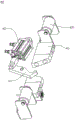
Fig. 1 is a schematic structural diagram of a PCB board receiving machine according to an embodiment of the present invention.
Fig. 2 is a schematic structural view of the first transfer device in fig. 1.
Fig. 3 is an enlarged view at a in fig. 2.
Fig. 4 is a schematic structural view of the striker mechanism in fig. 3.
Fig. 5 is a schematic structural view of the taking device in fig. 1.
Fig. 6 is a schematic view of the take-off mechanism of fig. 5.
Fig. 7 is a schematic structural view of the plate-adjusting mechanism in fig. 5.
Fig. 8 is a schematic structural diagram of the buffer device in fig. 1.
Fig. 9 is a schematic structural view of the second transfer device in fig. 1.
FIG. 10 is a schematic view of the drop mechanism of FIG. 1 in cooperation with a locking mechanism.
Fig. 11 is a schematic view of the locking mechanism of fig. 10.
Description of reference numerals:
100. a PCB collecting machine; 101. a frame;
10. a first conveying device; 11. a transfer assembly; 111. a first roller; 112. a second roller; 12. a centering positioning mechanism; 13. a stock stop mechanism; 131. a material blocking cylinder; 132. a baffle plate; 133. a guide bar;
20. a material taking device; 21. a material taking mechanism; 211. a material taking cylinder; 212. a connecting rod assembly; 213. placing an object; 22. a plate arranging mechanism; 221. a whole plate cylinder; 222. a monolith assembly; 2221. pushing the material piece; 223. a first guide assembly; 224. a second guide assembly;
30. a temporary storage device; 31. a lifting cylinder; 32. a discharging part; 321. a discharging part; 322. a back plate; 323. a rolling member;
40. a second conveying device; 41. a conveyor belt; 42. a motor; 43. an avoidance part;
50. a discharging mechanism;
60. a locking mechanism; 61. a locking member; 62. locking the air cylinder; 63. a third roller; 64. a guide member; 641. a guide portion.
70. A carrying device; 71. a positioning member; 72. and a fixing member.
Detailed Description
In order to explain technical contents and structural features of the present invention in detail, the following description is made with reference to the embodiments and the accompanying drawings.
Referring to fig. 1, the present invention provides a PCB board receiving machine 100, which includes a first conveying device 10, a material taking device 20, a temporary storage device 30 and a second conveying device 40 disposed on a frame 101. The second conveyor 40 is provided with a discharging mechanism 50 moving with the second conveyor 40, and the discharging mechanism 50 is used for discharging and is separated from the second conveyor 40. Specifically, the first conveying device 10 is used for docking various processing equipment, and the first conveying device 10 can convey the PCB board on the corresponding processing equipment to the material taking device 20. And the taking device 20 is located between the first conveying device 10 and the second conveying device 40, and the taking device 20 is used for taking the PCB on the first conveying device 10 and placing the PCB on the discharging mechanism 50 or the temporary storage device 30. The temporary storage device 30 is used for temporarily storing the PCB board, and the temporary storage device 30 is telescopically arranged on the rack 101. When one drop off mechanism 50 is full and the next process step is being fed, the empty drop off mechanisms 50 are not yet docked. At this time, the temporary storage device 30 may be lifted to the second conveying device 40, the picking device 20 may first place the PCB boards conveyed by the first conveying device 10 on the temporary storage device 30, and after the empty discharging mechanism 50 is in place, the temporary storage device 30 is lowered into the rack 101. When all the PCB boards on the temporary storage device 30 descend along with the temporary storage device 30, the PCB boards can fall into the empty discharging mechanism 50, the structure is simple, the design is reasonable, the production is uninterrupted, and the production efficiency is greatly improved.
After the technical scheme above is adopted, the utility model discloses a PCB board receiving machine 100, including setting up first conveyor 10, extracting device 20, temporary storage device 30 and the second conveyer 40 on frame 101. The first conveying device 10 is used for butting various PCB processing devices so as to receive and release processed PCBs to the discharging mechanism 50. The drop out mechanism 50 is transported on the second conveyor 40 to receive PCB boards from the first conveyor 10. The taking device 20 is used for taking the PCB conveyed on the first conveyor 10 to the second conveyor 40 or the temporary storage device 30. When the discharging mechanism 50 on the second conveyor 40 is full of material, the discharging mechanism 50 carries the PCB to the next process. At this time, the temporary storage device 30 is used for temporarily storing the PCB from the first conveyor 10, and when the empty discharge mechanism 50 is conveyed on the second conveyor 40, the PCB temporarily stored on the temporary storage device 30 can be automatically placed on the discharge mechanism 50, so that uninterrupted operation is performed, and the production efficiency is greatly improved. The utility model discloses a PCB board receiving machine 100 can dock multiple processing equipment and receive the board to the PCB board automatically, and receives the board efficiently.
Referring to fig. 1 to 3, in some alternative embodiments, the first conveying device 10 includes a conveying assembly 11 for conveying the PCB board, and the conveying assembly 11 includes a first roller 111 and a second roller 112. The first roller 111 may carry the PCB to be conveyed along the conveying direction of the first conveying device 10, and the first roller 111 is disposed so that the PCB is in rolling contact with the first roller 111 when the PCB is conveyed on the first conveying device 10, thereby reducing friction and preventing damage to the PCB. The rolling direction of second gyro wheel 112 is perpendicular to the rolling direction of first gyro wheel 111, and second gyro wheel 112 can take the PCB board to remove between the locating component of both sides, is provided with second gyro wheel 112 and makes the PCB board when controlling centering, and PCB board and second gyro wheel 112 rolling contact to reduce the friction, in order to avoid damaging the PCB board. Specifically, a centering mechanism 12 is disposed on the conveying assembly 11, the centering mechanism 12 includes two positioning assemblies disposed on two sides of the conveying assembly 11, and the two positioning assemblies operate to convey the PCB according to a predetermined track. Two locating component move near each other promptly for the PCB board of conveying on conveying component 11 can move toward middle direction, thereby makes the PCB board conveying between two parties, in order to ensure that extracting device 20 can get the material to the PCB board. It will be appreciated that the pre-set track is the path of the central transport on the transport assembly 11.
Referring to fig. 2 and 4, in some alternative embodiments, a movable material blocking mechanism 13 is further disposed on the first conveying device 10, and the material blocking mechanism 13 acts to suspend the PCB conveyed on the first conveying device 10 for the material taking device 20 to take materials. Specifically, the material blocking mechanism 13 includes a material blocking cylinder 131 and a baffle 132 located at an output end of the material blocking cylinder 131, and the material blocking cylinder 131 acts to make the baffle 132 move telescopically along the guide rod 133, so that the baffle 132 can protrude out of the first conveying device 10, and the PCB conveyed on the first conveying device 10 can be paused. The material blocking mechanism 13 is arranged, so that the conveying of the PCB can be delayed, and the material taking device 20 can successfully take materials. Or before the material taking device 20 is not reset, when the PCB is close to the material taking device 20 on the first conveying device 10, the material blocking mechanism 13 may block the material, so as to prevent the PCB from missing the material taking device 20.
Referring to fig. 5-7, in some alternative embodiments, the material extracting apparatus 20 includes a material extracting mechanism 21 and a plate arranging mechanism 22. The material taking mechanism 21 is rotatably disposed on the frame 101, the material taking mechanism 21 acts to drive the PCB on the first conveying device 10 to turn over a predetermined angle to be close to the material placing mechanism 50 on the second conveying device 40, and the board arranging mechanism 22 acts to make the PCB on the material taking mechanism 21 stand on the material placing mechanism 50 or on the temporary storage device 30. The preset angle is a rotation angle from the horizontal direction to the vertical direction, and may be any angle between 100 ° and 135 °, for example. Specifically, the material taking mechanism 21 includes a material taking cylinder 211 and a connecting rod assembly 212 located at an output end of the material taking cylinder 211, the connecting rod assembly 212 is provided with an object placing member 213, and the material taking cylinder 211 acts to enable the connecting rod assembly 212 to drive the object placing member 213 to turn over by a preset angle. The one end of putting article 213 is provided with and is the spacing portion that colludes the form, when the PCB board conveying was to touching spacing portion, gets material cylinder 211 and starts, and spacing portion can ensure to put article 213 and drive the position of PCB board upset unanimous at every turn, is provided with spacing portion moreover and can make the more firm placing of PCB board with put on article 213 to can be better overturn.
Referring to fig. 7, in some alternative embodiments, the whole board mechanism 22 includes a whole board cylinder 221 and a material pushing member 2221 disposed on the material pushing member 222, the material pushing member 2221 is disposed on the material pushing member 222, and the material pushing member 2221 acts on the PCB board by the action of the whole board cylinder 221, so that the PCB board disposed on the material taking mechanism 21 is supported by the material placing mechanism 50 or the temporary storage device 30. It can be understood that after the material taking mechanism 21 turns the PCB, the PCB is located on the discharging mechanism 50, but the PCB is not necessarily located close to the discharging mechanism 50, so that the PCB needs to be pushed backwards by the board arranging mechanism 22, so that the discharging position of the PCB on the discharging mechanism 50 is better. The pushing member 2221 has a flexible structure, so that the PCB board can be prevented from being damaged when the pushing member 2221 acts on the PCB board. The whole board mechanism 22 further includes a first guiding component 223 and a second guiding component 224, and the first guiding component 223 and the second guiding component 224 are arranged to enable the PCB to be in rolling contact with the whole board mechanism 22 in all directions when the PCB passes through the whole board mechanism 22, so that friction can be reduced, and yield can be increased.
Referring to fig. 8, in some alternative embodiments, the buffer device 30 includes a lifting cylinder 31 and a material placing member 32, the lifting cylinder 31 is installed in the frame 101, and the material placing member 32 is installed at the output end of the lifting cylinder 31. The elevating cylinder 31 is operated to make the discharging member 32 slide up and down to protrude out of the second transferring device 40. Specifically, the discharging member 32 includes a discharging portion 321 for temporarily discharging the PCB and a back plate 322 for supporting the PCB to stand, a plurality of rolling members 323 are disposed on two sides of the back plate 322, and the rolling members 323 are in rolling contact with the PCB. A plurality of rolling members 323 are provided on the back plate 322, and the PCB board is seated on the rolling members 323 and is in rolling contact with the rolling members 323, so that direct friction between the PCB board and the back plate 322 can be reduced to prevent the PCB board from being damaged. As shown in fig. 1 and 9, the second conveyor 40 includes a conveyor belt 41, and the conveyor belt 41 is used for conveying the discharge mechanism 50. The second conveyor 40 further includes a motor 42 for driving the conveyor belt 41 to convey. An escape portion 43 for lifting the buffer device 30 is further provided in the middle of the second conveyor 40. After the discharging mechanism 50 is filled with the material, the discharging mechanism 50 is transferred to the loading device 70 by the second transfer device 40, and the discharging mechanism 50 on which the PCB is placed is transferred to the next process by the loading device 70.
Referring to fig. 10 and 11, in some alternative embodiments, the PCB board collecting machine 100 further includes a loading device 70 separable from the frame 101, a locking mechanism 60 lockable with the loading device 70 is disposed at an end of the first conveying device 10 away from the material fetching device 20, a positioning member 71 cooperating with the locking mechanism 60 is disposed on the loading device 70, and the locking mechanism 60 cooperates with the positioning member 71 to lock the loading device 70 to the frame 101. A guide 64 for guiding the moving device is further provided on the frame 101, and the guide 64 is provided with a guide portion 641. The discharging mechanism 50 is provided with a fixing member 72 for fixing the positioning member 71, and the positioning member 71 is engaged with the guide portion 641 so that the locking mechanism 60 can be locked to the positioning member 71. The guiding portion 641 has a concave structure recessed inwards, and the fixing member 72 has a convex structure matching with the concave structure, so that the position of the loading device 70 at each stop is fixed by the fixing member 72 matching in the guiding portion 641, and the locking mechanism 60 can lock the loading device 70. The locking mechanism 60 includes a locking member 61 movably locked with the positioning member 71, the locking member 61 is disposed at an output end of the locking cylinder 62, and the locking cylinder 62 operates to lock the locking member 61 to the positioning member 71 when the fixing member 72 is engaged with the guide portion 641. The locking mechanism 60 is further provided with third rollers 63 on both sides, so that the discharging mechanism 50 can be more conveniently moved from the moving device to the second conveying device 40 by the third rollers 63.
As shown in fig. 1 to 11, the PCB board receiving machine 100 of the present invention includes a first conveying device 10, a material taking device 20, a temporary storage device 30 and a second conveying device 40 disposed on a frame 101. The first conveying device 10 is used for butting various PCB processing devices so as to receive and release processed PCBs to the discharging mechanism 50. The drop out mechanism 50 is transported on the second conveyor 40 to receive PCB boards from the first conveyor 10. The material taking mechanism 21 in the material taking device 20 takes the PCB conveyed on the first conveying device 10 to turn over, and places the turned PCB on the discharging mechanism 50 of the second conveying device 40, or places the turned PCB on the temporary storage device 30. The placement of the PCB board is then made better by the board alignment mechanism 22. When the discharging mechanism 50 on the second conveyor 40 is full, the discharging mechanism 50 carries the PCB board with the carrier device 70 to the next process. At this time, the temporary storage device 30 is used for temporarily storing the PCB from the first conveyor 10, and when the empty discharge mechanism 50 is conveyed on the second conveyor 40, the PCB temporarily stored on the temporary storage device 30 can be automatically placed on the discharge mechanism 50, so that uninterrupted operation is performed, and the production efficiency is greatly improved. The utility model discloses a PCB board receiving machine 100 can dock multiple processing equipment and receive the board to the PCB board automatically, and receives the board efficiently.
The above disclosure is only a preferred embodiment of the present invention, and the scope of the claims of the present invention should not be limited thereby, and all the equivalent changes made in the claims of the present invention are intended to be covered by the present invention.
Claims (10)
1. A PCB board collecting machine is characterized by comprising a first conveying device, a material taking device, a temporary storage device and a second conveying device which are arranged on a rack, wherein a material discharging mechanism moving along with the second conveying device is arranged on the second conveying device, and the first conveying device is used for butting processing equipment and conveying a PCB board on the processing equipment to the material taking device; the material taking device is positioned between the first conveying device and the second conveying device and used for placing the PCB on the first conveying device on the discharging mechanism or the temporary storage device; the temporary storage device is used for temporarily storing the PCB, and the temporary storage device is arranged on the rack in a telescopic mode.
2. A PCB board collecting machine according to claim 1, wherein the first conveying device comprises a conveying assembly for conveying the PCB board, the conveying assembly is provided with a centering mechanism, the centering mechanism comprises two positioning assemblies oppositely arranged at two sides of the conveying assembly, and the two positioning assemblies act to convey the PCB board according to a preset track.
3. The PCB board collecting machine of claim 1, wherein a movable stop mechanism is further arranged on the first conveying device, and the stop mechanism acts to pause the PCB board conveyed on the first conveying device so as to be taken by the taking device.
4. The PCB board collecting machine of claim 3, wherein the material blocking mechanism comprises a material blocking cylinder and a baffle plate positioned at the output end of the material blocking cylinder, and the material blocking cylinder acts to enable the baffle plate to protrude out of the first conveying device so as to pause the PCB board conveyed on the first conveying device.
5. A PCB board collecting machine as claimed in claim 1, wherein the material taking device includes a material taking mechanism and a board arranging mechanism, the material taking mechanism is rotatably disposed on the frame, the material taking mechanism is operated to drive the PCB board on the first conveying device to turn over a predetermined angle to be close to the material discharging mechanism on the second conveying device, and the board arranging mechanism is operated to make the PCB board on the material taking mechanism stand against the material discharging mechanism or against the temporary storage device.
6. The PCB board collecting machine of claim 5, wherein the material taking mechanism comprises a material taking cylinder and a connecting rod assembly positioned at the output end of the material taking cylinder, an object is arranged on the connecting rod assembly, and the material taking cylinder acts to enable the connecting rod assembly to drive the object placing member to turn over by a preset angle.
7. The PCB board collecting machine of claim 5, wherein the board collecting mechanism comprises a board collecting cylinder and a material pushing component arranged at the output end of the board collecting cylinder, a material pushing member in a flexible structure is arranged on the material pushing component, and the material pushing member acts on the PCB board by the action of the material pushing cylinder, so that the PCB board on the material taking mechanism is abutted against the material discharging mechanism or the temporary storage device.
8. A PCB board collecting machine according to claim 1, wherein the temporary storage means comprises a lifting cylinder and a discharge member, the lifting cylinder being mounted in the frame, the lifting cylinder acting to project the discharge member out of the second conveyor.
9. The PCB board collecting machine of claim 8, wherein the discharging part comprises a discharging part for temporarily discharging the PCB board and a back plate for the PCB board to stand, a plurality of rolling parts are arranged on two sides of the back plate, and the rolling parts are in rolling contact with the PCB board.
10. The PCB board collecting machine of claim 1, further comprising a carrying device separable from the frame, wherein a locking mechanism lockable with the carrying device is arranged at an end of the first conveying device away from the material taking device, a positioning member matched with the locking mechanism is arranged on the carrying device, and the locking mechanism is matched with the positioning member to lock the carrying device on the frame.
Priority Applications (1)
| Application Number | Priority Date | Filing Date | Title |
|---|---|---|---|
| CN202120708229.6U CN215207260U (en) | 2021-04-07 | 2021-04-07 | PCB board collecting machine |
Applications Claiming Priority (1)
| Application Number | Priority Date | Filing Date | Title |
|---|---|---|---|
| CN202120708229.6U CN215207260U (en) | 2021-04-07 | 2021-04-07 | PCB board collecting machine |
Publications (1)
| Publication Number | Publication Date |
|---|---|
| CN215207260U true CN215207260U (en) | 2021-12-17 |
Family
ID=79445682
Family Applications (1)
| Application Number | Title | Priority Date | Filing Date |
|---|---|---|---|
| CN202120708229.6U Active CN215207260U (en) | 2021-04-07 | 2021-04-07 | PCB board collecting machine |
Country Status (1)
| Country | Link |
|---|---|
| CN (1) | CN215207260U (en) |
-
2021
- 2021-04-07 CN CN202120708229.6U patent/CN215207260U/en active Active
Similar Documents
| Publication | Publication Date | Title |
|---|---|---|
| CN107262954B (en) | Battery welding machine | |
| CN106184878B (en) | Ceramic tile automated packaging equipment | |
| KR20090069530A (en) | Automatic supply and retrieval methods of tray and the automatic supply and retrieval device thereof | |
| CN215207260U (en) | PCB board collecting machine | |
| CN111606026B (en) | Automatic stores pylon equipment of cell-phone battery case of unloading on unilateral | |
| CN207121185U (en) | A kind of conveying, turning device for white body door closure production line lower part | |
| CN109795394A (en) | Swing lift railway platform, swing lift system and handling method | |
| CN215248299U (en) | Intelligent unloading device | |
| CN110600827B (en) | Battery disassembling system | |
| TWI690251B (en) | Vertical hanger investment board machine | |
| CN210557717U (en) | Load transferring and blanking device | |
| KR102037725B1 (en) | System for transporting goods | |
| JP2004313116A (en) | Apparatus for stacking raising seedling box | |
| CN216248759U (en) | Double-row double-side exposure machine | |
| JP5392625B2 (en) | Loading guide mounting device and mounting method | |
| JP6689714B2 (en) | Container processing equipment | |
| CN215207129U (en) | PCB (printed circuit board) putting machine | |
| CN113859995B (en) | Discharging device, discharging method and logistics conveying system | |
| JP2538948B2 (en) | Work transfer device | |
| CN111037528A (en) | Bracket for PCB | |
| CN212162006U (en) | Traceable lead storage battery shell acid injection device | |
| JP5532340B2 (en) | Goods transport equipment | |
| CN219928910U (en) | Material throwing and collecting equipment | |
| CN219990463U (en) | Automatic rubber coating equipment | |
| CN217837457U (en) | Full-automatic 4 stations take plasma of paper function of separating to go up blanking machine |
Legal Events
| Date | Code | Title | Description |
|---|---|---|---|
| GR01 | Patent grant | ||
| GR01 | Patent grant |