CN215183813U - High-breaking miniature circuit breaker - Google Patents
High-breaking miniature circuit breaker Download PDFInfo
- Publication number
- CN215183813U CN215183813U CN202120942542.6U CN202120942542U CN215183813U CN 215183813 U CN215183813 U CN 215183813U CN 202120942542 U CN202120942542 U CN 202120942542U CN 215183813 U CN215183813 U CN 215183813U
- Authority
- CN
- China
- Prior art keywords
- contact part
- circuit breaker
- locking
- rotating wheel
- driving plate
- Prior art date
- Legal status (The legal status is an assumption and is not a legal conclusion. Google has not performed a legal analysis and makes no representation as to the accuracy of the status listed.)
- Active
Links
Images


Landscapes
- Breakers (AREA)
Abstract
The utility model discloses a high-breaking miniature circuit breaker, including the handle structure who sets up in the casing, the dropout subassembly, contact structure and drive structure, the dropout subassembly includes the runner of rotatable setting in the casing, drive structure includes the drive plate of ground butt joint between runner and movable contact part, and set up the lock plate that is located the rotation circuit of drive plate and runner respectively, the drive plate forms the locking cooperation with the lock plate in the switching-on rotation process, through runner drive lock plate and drive plate release locking cooperation, so that make movable contact part and static contact instantaneous contact, the miniature circuit breaker who adopts this technical scheme possesses the characteristics of quick switch-on and breaking circuit, reduce the fusion welding risk of contact, be favorable to shortening the arc extinguishing time between the movable contact, the static contact, alleviate to cause the electric corrosion to the contact, improve the electric life, can bear high voltage for traditional circuit breaker, the use requirement of the high-voltage circuit can be well met, and the setting cost is reduced.
Description
Technical Field
The utility model relates to a low-voltage apparatus technical field, concretely relates to high disconnected miniature circuit breaker that divides.
Background
Miniature circuit breakers are used in low voltage protective devices for making or breaking loads and protecting lines and equipment in electrical power distribution systems. It not only has the function of manual switch, but also can automatically implement the functions of voltage-loss, undervoltage, overload and short-circuit protection, so that it can be used for distributing electric energy, starting asynchronous motor infrequently, protecting power supply circuit and motor, etc. and can automatically cut off circuit when they are seriously overloaded or short-circuited and undervoltage, etc. are produced.
When the miniature circuit breaker is used for a photovoltaic circuit, along with the continuous development of the photovoltaic technology industry and the centralized power distribution requirement, the electric appliance requires that the breaking capacity of the miniature circuit breaker is higher and higher, and the traditional miniature circuit breaker cannot be well used for the photovoltaic circuit due to small opening distance and low breaking capacity. The traditional miniature circuit breaker generally comprises an electromagnetic protection system, a thermal tripping system, an arc extinguishing system, an operation tripping mechanism and the like, wherein the operation tripping mechanism is a component for driving the circuit breaker to open or close, the operation tripping mechanism ensures that the circuit breaker is reliably closed and also ensures that the circuit breaker is quickly opened in a fault state, and therefore, the performance of the operation tripping mechanism directly influences the breaking capacity of the miniature circuit breaker, so that the closing speed and the opening speed of the circuit breaker are related to the breaking capacity of the circuit breaker.
For example, chinese patent document CN205428852U discloses an operating mechanism of a miniature circuit breaker, which includes a static contact fixedly installed in a housing, a handle pivotally installed on the housing, a transmission link hinged with the handle, a latch hinged with the transmission link, and a trip buckle, and further includes a lever coaxially sleeved on a mechanism rotating shaft, a contact frame and a moving contact, the moving contact is installed on the contact frame, the contact frame is connected with the lever through an over-travel torsion spring, the latch and the trip buckle are pivotally installed on the lever respectively, and form interlocking fit with each other; the handle drives the lever to rotate around the rotating shaft of the mechanism through the transmission connecting rod and the lock catch, and then the lever drives the contact head frame and drives the moving contact to coaxially rotate around the rotating shaft of the mechanism, so that the moving contact and the static contact are closed.
It can be seen from the structure of the above-mentioned operating mechanism that it adopts the traditional mode of directly driving the moving contact frame and the moving contact to rotate by the handle through the transmission connecting rod, the jump buckle, the lock catch and the lever, and it has the following problems: 1. the handle gradually transmits the motion to the contact frame through the transmission connecting rod, the jump buckle, the lock catch and the lever, and the rotating speed of the contact frame is controlled by the handle to a great extent, so that the connection speed of the circuit breaker is easily influenced, the fusion welding risk of the contact is caused, and the high-voltage circuit quick connection capability and the breaking capability of the circuit breaker are not realized; 2. secondly, the breaking speed of the circuit breaker is influenced, the breaking capacity of a high-voltage circuit is relatively poor, the arc extinguishing time between a moving contact and a fixed contact is long, the contact is electrically corroded, and the electrical service life is shortened; in conclusion, the traditional micro circuit breaker is not high enough in breaking capacity, does not have the capacity of quickly connecting and breaking a high-voltage circuit, needs to be connected in series to increase voltage, and is large in occupied size and high in setting cost.
SUMMERY OF THE UTILITY MODEL
Therefore, the technical problem to be solved by the present invention is to overcome the fusion welding risk of the contact caused by the slow switching-on speed of the micro circuit breaker in the prior art, and the ability of quickly switching on the high voltage circuit is not provided; and the problem that the breaking speed of the circuit breaker is low, the electric corrosion can be caused to the contact, the capacity of quickly breaking the high-voltage circuit is not provided, and the breaking capacity of the circuit breaker is influenced is solved, so that the high-breaking miniature circuit breaker which has the advantages of quickly connecting and breaking the circuit, prolonging the electrical service life of a product and meeting the use requirement of the high-voltage circuit is provided.
In order to solve the technical problem, the utility model provides a high disconnected miniature circuit breaker that divides, include:
the handle structure is rotatably arranged on the shell;
the tripping assembly is in linkage fit with the handle structure and comprises a rotating wheel which is rotatably arranged on the shell, and the tripping assembly has a switching-on state which drives the rotating wheel to rotate in the forward direction during switching-on motion of the handle structure and a switching-off state which drives the rotating wheel to rotate in the reverse direction during switching-off motion of the handle structure;
the contact structure comprises a fixed contact fixed on the shell, a movable contact part movably arranged on the shell relative to the fixed contact, and an elastic part arranged between the movable contact part and the shell, wherein the elastic part applies elastic force moving close to the fixed contact direction to the movable contact part;
the driving structure comprises a driving plate which is in rotary butt joint between the rotating wheel and the movable contact part, and a locking plate which is movably arranged on the shell and is positioned on a moving path of the rotating wheel, the driving plate is connected with the rotating wheel and the movable contact part, and the locking plate is in contact with the driving plate on a rotating track of the driving plate;
when the handle structure is switched on, the rotating wheel is driven to rotate in the forward direction, the driving plate is pushed by the movable contact part to rotate and abut against the rotating wheel, and forms locking fit with the locking plate after abutting against the rotating wheel to rotate for a certain stroke, so that the movable contact part and the static contact keep a certain distance, the rotating wheel is driven to rotate relative to the driving plate on the way, the locking plate and the driving plate are driven to release the locking fit, and the driving plate jumps to one side of the rotating wheel under the pushing of the movable contact part, so that the movable contact part is in contact with the static contact under the action of the elastic force; when the handle structure is in brake opening, the rotating wheel is driven to rotate reversely, and the driving plate pushes the movable contact part under the driving of the rotating wheel so as to drive the movable contact part to be separated from the fixed contact by overcoming the elastic force.
In the high breaking miniature circuit breaker, the handle structure comprises a handle and a snap button seat which are coaxially and rotatably arranged on the shell, a torsion spring structure arranged between the handle and the snap button seat, and a swing rod connecting the snap button seat and the tripping component, and a stroke gap is formed between the handle and the snap button seat when the handle is at a switching-on position or a switching-off position; when the handle moves from a switch-on position to a switch-off position, the snap button seat is pushed to rotate towards a position close to a breaking balance point, when the snap button seat drives the swing rod to cross the breaking balance point, the snap button seat is driven by the torsion spring structure to snap and rotate towards the stroke gap, and the swing rod drives the tripping assembly to switch from a switch-on state to a switch-off state, so that the driving plate drives the movable contact part to move towards a direction far away from the fixed contact under the pushing of the rotating wheel.
In the high breaking micro circuit breaker, the handle is provided with an arc-shaped knob part overlapped with a rotation path of the snap-through knob seat, the arc-shaped knob part and the snap-through knob seat are arranged around a rotation center of the handle, and when one end of the arc-shaped knob part pushes the snap-through knob seat to rotate, the other end of the arc-shaped knob part and the snap-through knob seat form the stroke gap.
In the high breaking micro circuit breaker, the stroke gap is an arc-shaped groove which is arranged between the arc-shaped knob part and the snap-through knob seat around the rotation center; and the snap-through button seat reaches the breaking balance point position when the matching point of the oscillating bar and the tripping component, the matching point of the oscillating bar and the snap-through button seat and the rotation center of the handle are sequentially connected in a straight line.
In the high-breaking miniature circuit breaker, the drive board is rotatably disposed above the movable contact part and includes a first contact portion abutting against the top of the movable contact part and a second contact portion abutting against the rotating wheel, a limit boss abutting against the second contact portion in a matched manner is disposed on a side wall of the rotating wheel, and the drive board drives the second contact portion to rotatably abut against the limit boss when the first contact portion is pushed by the movable contact part.
In the high-breaking miniature circuit breaker, the driving plate comprises a locking end extending towards one side of the locking plate, the locking plate comprises a hook end with a hook groove, and the locking end is matched with the hook end in the rotating process of the driving plate in a locking mode.
In the high-breaking miniature circuit breaker, the locking plate is rotatably arranged on the shell, and rotates in the direction away from the driving plate when being pushed by the rotating wheel so as to release the locking fit between the locking end and the hook end, and a reset torsion spring is arranged between the locking plate and the shell; the driving plate has a locking state which limits the moving contact part to move towards the direction of the fixed contact when forming locking matching with the locking plate, and has a kick state which does not limit the moving contact part to be in moving contact with the fixed contact when releasing the locking matching with the locking plate.
In the above high-breaking miniature circuit breaker, when the rotary wheel rotates forward relative to the drive plate in the locked state, a gap is formed between the limit boss and the second contact portion, and the second contact portion rotates suddenly at the position of the gap after the drive plate and the locking plate are unlocked and matched.
In the high breaking micro circuit breaker, the movable contact part comprises: the contact device comprises a contact frame, a movable contact bridge and two movable contacts, wherein the contact frame can be arranged on the shell in a reciprocating mode, the movable contact bridge is horizontally arranged on the contact frame, the two movable contacts are arranged at two ends of the movable contact bridge, the elastic part is a spring arranged between the bottom end of the contact frame and the shell, and two fixed contacts which are vertically opposite to the two movable contacts are arranged in the shell; the driving plate abuts against the top end of the contact frame through a first contact part.
In the high breaking miniature circuit breaker, the tripping assembly comprises a locking piece and a limiting piece which are respectively connected with the rotating wheel in a pivoting manner through a connecting shaft, and a brake separating spring connected between the rotating wheel and the shell, wherein the brake separating spring applies elastic force for reverse rotation to the rotating wheel, and a limiting slot hole for connecting one end of the oscillating bar is formed between the locking piece and the rotating wheel; the lock catch piece and the limiting piece form linkage locking cooperation when the tripping assembly is in a closing state, and form separated tripping cooperation when the tripping assembly is in a breaking state.
In the high-breaking miniature circuit breaker, the casing is rotatably provided with a trip lever connected with the limiting part, the trip lever is driven by an electromagnetic trip mechanism or a thermal overload mechanism of the circuit breaker to drive the limiting part to be separated from the lock catch part in a trip mode, so that the swing rod slips from the limiting slotted hole, the rotating wheel drives the driving plate to rotate under the action of the opening spring, and the movable contact part is forced to be separated from the fixed contact under the pushing of the driving plate.
The technical scheme of the utility model compare and have following advantage in prior art:
1. the utility model provides an among the high disconnected miniature circuit breaker that divides, through tripping assembly, drive plate, cooperation between the lock plate realizes closing in the twinkling of an eye between movable contact part and the static contact, through handle structure, tripping assembly, cooperation between the drive plate realize the separating brake in the twinkling of an eye between movable contact part and the static contact, make the utility model discloses a miniature circuit breaker possesses the characteristics of quick switch-on and separating circuit to can accomplish bigger with miniature circuit breaker's voltage specification, can bear the high voltage and can fine messenger be arranged in high voltage circuit for traditional circuit breaker, avoid the mode of the reuse to a plurality of circuit breaker series connection assembly, reduce installation occupation space, satisfy user's user demand, reduce the cost of setting.
2. The utility model provides an among the high disconnected miniature circuit breaker that divides, movable contact part receives the effect of elastic force to promote drive plate rotation butt in the runner, stop respectively through runner and lock plate that the rotation of drive plate restricts the movable contact part and is close to the static contact and remove, consequently, drive the runner forward rotation when handle structure combined floodgate motion, the drive plate can support to rotate a section stroke by the runner owing to receive the push action of movable contact part, and then keep the locking state when forming the locking cooperation with the lock plate, movable contact part moves gradually and is close to the moving contact in the drive plate rotation process, but the two still do not contact and a segment interval, continue forward rotation through the runner and remove the locking cooperation with the drive plate, at this moment the drive plate also removes the locking effect to the movable contact part, makes quick jump of movable contact part and static contact in the twinkling of an eye, promote simultaneously the drive plate jumps fast, realizes the quick combined floodgate of circuit breaker, adopts this technical scheme, realizes the kick combined floodgate between movable contact spare and the static contact through the cooperation of runner, drive plate, lock plate, improves the switching-on speed of circuit breaker greatly, reduces the melting welding risk of moving contact, makes the circuit breaker possess the ability of high voltage circuit of quick switch-on, promotes the breaking capacity and the performance of circuit breaker.
3. The utility model provides an among the high disconnected miniature circuit breaker that divides, when pulling the handle and carrying out the breaking motion, the handle contacts the sudden jump button seat after rotating the idle stroke of certain angle, when promoting the sudden jump button seat to rotate together and cross disconnected equilibrium point position, according to forming the stroke clearance (this stroke clearance is along with the rotation of handle between handle and the sudden jump button seat transform the position and can not disappear) between the handle and the sudden jump button seat, the sudden jump button seat takes place the sudden jump in the stroke clearance under the effect of torsional spring structure, through pendulum rod drive tripping assembly switch-on state to the state of separating brake, at this moment runner antiport is in order to promote the drive plate to exert the effort to the moving contact part, thereby compel the motion, the static contact is kept away from in the twinkling of an eye and is disconnected, realize the quick separating brake of circuit breaker, improve circuit breaker speed greatly, reduce the production of electric arc, be favorable to shortening the arc extinguishing time, improve arc extinguishing efficiency, avoid the long-time burning of electric arc to cause the electrical corrosion to the contact, even burn out, improve electric life, make the circuit breaker possess the ability of connecing fast and divide the circuit of pressing out the power supply circuit, promote the breaking capacity and the performance of circuit breaker.
4. The utility model provides an among the high disconnected miniature circuit breaker, the drive plate has to being close to lock plate direction pivoted trend under the impetus that receives movable contact part, when the locking cooperation that drive plate and lock plate passed through locking end and couple end formed keeps the relative position locking, makes the drive plate locking at the locking state not rotate and exert reaction force to moving contact part, is used for the restriction moving contact part continues to be close to the static contact and removes, and at this moment there is a segment distance between moving contact part and the static contact to close a floodgate in the twinkling of an eye for moving contact part next time and provide the kick clearance, as long as when the locking cooperation is relieved to drive plate and lock plate, can realize the fast switch-on between moving contact and the static contact, has weakened the impact force between the contact again.
5. The utility model provides an among the high disconnected miniature circuit breaker that divides, two moving contacts that the static contact corresponds movable contact bridge both ends are provided with two, the movable contact bridge drives two moving contacts and two static contacts and contacts or separate when following the contact carrier and reciprocating, this kind of structural design's contact structure is two breakpoint structural style, the space of mechanism has been reduced, and cooperation drive plate and this kind of new mechanism of tripping assembly use, can double increase the opening distance, shorten the time of arc extinguishing, improve direct current voltage and disconnected ability, the electrocorrosion of contact also reduces simultaneously, the electrical life is prolonged.
Drawings
In order to more clearly illustrate the embodiments of the present invention or the technical solutions in the prior art, the drawings used in the embodiments or the technical solutions in the prior art will be briefly described below, and it is obvious that the drawings in the following description are some embodiments of the present invention, and for those skilled in the art, other drawings can be obtained according to these drawings without creative efforts.
Fig. 1 is a schematic structural diagram of the high breaking micro circuit breaker of the present invention in a breaking state;
fig. 2 is a schematic structural view of the high breaking micro circuit breaker of the present invention in a locked state during a closing process;
fig. 3 is a schematic structural view of the high breaking micro circuit breaker of the present invention in an unlocking state during a closing process;
fig. 4 is a schematic structural diagram of the high breaking micro circuit breaker of the present invention in a closing state;
FIG. 5 is a schematic structural view of the handle structure of the present invention reaching the position of the breaking balance point;
fig. 6 is a schematic structural view of the handle structure and the trip assembly of the present invention;
fig. 7 is a schematic structural view of the trip bar and the trip assembly of the present invention, particularly illustrating the trip separation of the locking member and the limiting member;
fig. 8 is a schematic view of a split structure of the handle structure of the present invention;
fig. 9 is a schematic view of a split structure of the trip assembly of the present invention;
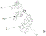
reference numerals: 1. a handle structure; 11. a handle; 12. a snap button seat; 13. a torsion spring structure; 14. a swing rod; 15. an arc knob portion; 16. a stroke gap; 2. a trip assembly; 21. a rotating wheel; 22. a fastener; 23. a limiting member; 24. a brake separating spring; 25. limiting slotted holes; 26. a limiting boss; 3. static contact; 4. A movable contact part; 41. a contact head frame; 42. a movable contact bridge; 43. a moving contact; 5. an elastic member; 6. a drive plate; 61. a first contact portion; 62. a second contact portion; 63. a locking end; 7. a lock plate; 71. a hooking end; 8. a housing; 9. a trip bar.
Detailed Description
The technical solution of the present invention will be described clearly and completely with reference to the accompanying drawings, and obviously, the described embodiments are some, but not all embodiments of the present invention. Based on the embodiments in the present invention, all other embodiments obtained by a person skilled in the art without creative work belong to the protection scope of the present invention.
In the description of the present invention, it should be noted that the terms "first", "second" and "third" are used for descriptive purposes only and are not to be construed as indicating or implying relative importance.
In the description of the present invention, it is to be noted that, unless otherwise explicitly specified or limited, the terms "mounted," "connected," and "connected" are to be construed broadly, and may be, for example, fixedly connected, detachably connected, or integrally connected; can be mechanically or electrically connected; they may be connected directly or indirectly through intervening media, or they may be interconnected between two elements. The specific meaning of the above terms in the present invention can be understood in specific cases to those skilled in the art.
Furthermore, the technical features mentioned in the different embodiments of the invention described below can be combined with each other as long as they do not conflict with each other.
Example 1
The present embodiment is described in detail below with reference to the accompanying drawings:
the utility model provides a divide miniature circuit breaker of high branch as shown in fig. 1-9, include:
the handle structure 1 is rotatably arranged on the shell;
the tripping assembly 2 is in linkage fit with the handle structure 1 and comprises a rotating wheel 21 which is rotatably arranged on the shell, and the tripping assembly 2 has a switching-on state which drives the rotating wheel 21 to rotate in the forward direction during switching-on motion of the handle structure and a switching-off state which drives the rotating wheel 21 to rotate in the reverse direction during switching-off motion of the handle structure 1;
the contact structure comprises a fixed contact 3 fixed on the shell, a movable contact part 4 movably arranged on the shell relative to the fixed contact, and an elastic part 5 arranged between the movable contact part 4 and the shell, wherein the elastic part 5 applies an elastic force to the movable contact part 4 to move in a direction close to the fixed contact 3;
the driving structure comprises a driving plate 6 which is in rotary butt joint between the rotating wheel 21 and the moving contact part 4, and a locking plate 7 which is movably arranged on the shell and is positioned on a motion path of the rotating wheel 21, wherein the driving plate 6 is connected with the moving contact part 4 and the rotating wheel 21 in the motion process, and the locking plate 7 is in contact with the driving plate 6 on the rotation track of the driving plate 6;
when the handle structure is switched on, the rotating wheel 21 is driven to rotate in the forward direction, the driving plate 6 is driven by the moving contact part to rotate and abut against the rotating wheel 21, and after the moving contact part rotates for a certain stroke and abuts against the rotating wheel 21, the driving plate 6 and the locking plate 7 form locking fit which enables the moving contact part 4 and the static contact 3 to keep a certain distance, and the rotating wheel 21 drives the locking plate 7 and the driving plate 6 to be unlocked and matched in the process of continuously rotating relative to the driving plate, so that the moving contact part 4 drives the driving plate 6 to jump suddenly and is in instant contact with the static contact 3; when the handle structure is in brake-off, the rotating wheel 21 is driven to rotate reversely, and the driving plate 6 is driven by the rotating wheel to push the moving contact part 4, so that the moving contact part 4 is driven to overcome the elastic force and is separated from the static contact 3 instantly.
In the above embodiment, according to the fact that the movable contact part 4 is acted by the elastic force to push the driving plate 6 to rotatably abut against the rotating wheel 21, the movable contact part 4 is prevented from moving close to the static contact 3 by abutting against the rotation of the driving plate, when the miniature circuit breaker is switched on, the handle structure 1 drives the rotating wheel 21 of the trip assembly 2 to rotate forward in the switching-on motion, the driving plate 6 rotates a section of stroke by abutting against the rotating wheel 21 due to the pushing action of the movable contact part 4, and then keeps a locking state when forming locking fit with the locking plate 7, and plays a locking role on the driving plate through the locking plate, during the process, the movable contact part 4 gradually moves close to the movable contact 43 in the rotation process of the driving plate 6, but the two are not yet contacted and still have a small opening distance, and after the locking plate 7 and the driving plate 6 are released from locking fit through the continuous forward rotation of the rotating wheel 21, the technical scheme is adopted, the sudden jump and the switch-on between the movable contact part 4 and the static contact 3 are realized through the matching of the rotating wheel 21, the driving plate 6 and the locking plate 7, the switch-on speed of the circuit breaker is greatly improved, the fusion welding risk of the contact is reduced, the circuit breaker has the capacity of quickly switching on a high-voltage circuit, and the breaking capacity and the service performance of the circuit breaker are improved. The forward rotation and the reverse rotation in this context do not indicate an actual rotation direction of a certain component, but indicate that two rotation directions of a certain component are different.
The specific arrangement of the handle structure is described in detail below with reference to fig. 1-6:
the handle structure 1 comprises a handle 11 and a snap button seat 12 which are coaxially and rotatably arranged on the shell, and a torsion spring structure 13 arranged between the handle 11 and the snap button seat 12, the snap button seat 12 is connected with the tripping component 2 through a swing rod 14, and a section of stroke gap 16 is formed between the handle 11 and the snap button seat 12 when the handle is at a switching-on position or a switching-off position; when the handle 11 moves from the closing position to the opening position, the snap button seat 12 is pushed to rotate towards the position close to the breaking balance point, referring to fig. 3, when the snap button seat 12 drives the swing rod 14 to cross the breaking balance point, the snap button seat is driven by the torsion spring structure 13 to snap rotate towards the inside of the stroke gap 16, and the swing rod 14 drives the tripping assembly 2 to switch from the closing state to the opening state, so that the driving plate 6 drives the movable contact part 4 to move towards the direction away from the fixed contact 3 under the pushing of the rotating wheel 21.
According to the structure, when the miniature circuit breaker is switched off, in the process of pulling the handle 11 to move from the switching-on position to the switching-off position, the handle 11 rotates for an idle stroke at a certain angle and then contacts the snap button seat 12, and then pushes the snap button seat 12 to rotate together and cross the position of a switching-off balance point, according to the fact that a stroke gap 16 is formed between the handle 11 and the snap button seat 12 (the stroke gap does not disappear as the handle rotates to change positions between the handle and the snap button seat), the snap button seat 12 jumps into the stroke gap 16 under the action of the torsion spring structure 13, the rotating wheel 21 rotates reversely under the action of the switching-off spring to push the driving plate 6 to apply acting force to the movable contact part 4, so that the movable contact and the static contact 3 are forced to be separated instantly, the quick switching-off of the circuit breaker is realized, and the switching-off speed of the circuit breaker is greatly improved, reduce the production of electric arc, be favorable to shortening arc extinguishing time, improve arc extinguishing efficiency, avoid the long-time burning of electric arc to cause the galvanic corrosion to the contact, burn even, improve electric life, make the circuit breaker possess the ability of connecing fast and dividing the voltage circuit, promote the breaking capacity and the performance of circuit breaker.
As a preferred embodiment, as shown in fig. 4-5, the handle 11 has an arc-shaped knob portion 15 overlapping with the rotation path of the snap button seat 12, the arc-shaped knob portion 15 and the snap button seat 12 are arranged around the rotation center of the handle 11, and when one end of the arc-shaped knob portion 15 pushes the snap button seat 12 to rotate, the other end thereof forms the stroke gap 16 with the snap button seat 12, wherein the stroke gap is an arc-shaped groove arranged between the arc-shaped knob portion 15 and the snap button seat 12 around the rotation center, and this structure is arranged such that when the handle 11 is at the on position, a stroke gap 16 exists between one end of the arc-shaped knob portion 15 and the snap button seat 12, and when the handle 11 moves from the on position to the off position, one end of the arc-shaped knob portion 15 contacts the snap button seat 12 after rotating through the stroke gap 16 due to the force component of the swing link 14, therefore, the snap button seat 12 is pushed to rotate together, a new stroke gap 16 is formed between the other end of the arc-shaped button part 15 and the snap button seat 12, the newly formed stroke gap 16 provides a position space required by snap when the snap button seat 12 crosses a breaking balance point position, the instant snap of the snap button seat 12 drives the rotating wheel 21 of the tripping component 2 to rapidly and reversely rotate, namely the tripping component 2 is triggered by the snap button seat 12 and the swing rod 14 to realize a tripping action, and the driving plate 6 drives the moving contact part 4 and the static contact 3 to be instantly separated when being pushed by the rotating wheel 21, so that the moving contact part 4 and the static contact 3 are rapidly broken.
Referring to fig. 5, the snap-through button seat 12 reaches the breaking balance point position when the matching point of the swing link 14 and the trip component 2, the matching point of the swing link 14 and the snap-through button seat 12, and the rotation center of the handle 11 are sequentially connected in a straight line, the breaking balance point position is the critical point of the snap-through button seat 12 for realizing snap-through during switching off, when the snap-through button seat 12 crosses the breaking balance point position, snap-through occurs under the action of the torsion spring, so that the trip component 2 is driven to be switched from the switching-on state to the switching-off state, and finally, snap-through breaking between the movable contact part 4 and the fixed contact 3 is realized through the transmission fit among the rotating wheel 21, the driving plate 6 and the movable contact part 4.
The specific arrangement of the driving plate 6 and the locking plate 7 will be described in detail below with reference to fig. 1 to 3 and 7:
the driving plate 6 is rotatably disposed above the movable contact member 4, and includes a first contact portion 61 abutting against the top of the movable contact member 4, and a second contact portion 62 abutting against the runner 21, a limit boss 26 abutting against the second contact portion 62 in a matching manner is disposed on a side wall of the runner 21, the driving plate 6 drives the second contact portion 62 to rotate against the limit boss 26 when the first contact portion 61 is pushed by the movable contact member 4, referring to fig. 2, a relative rotation position of the driving plate 6 is defined by the matching between the limit boss and the second contact portion 62, and then the driving plate 6 locks a movement position of the movable contact member 4, so that the movable contact member 4 is limited by the driving plate 6 and kept in a separation state from the static contact 3.
In order to reliably realize the locking fit between the driving plate 6 and the locking plate, the driving plate 6 comprises a locking end 63 extending towards one side of the locking plate 7, the locking plate 7 is rotatably arranged in the shell and comprises a hook end 71 with a hook groove, the driving plate 6 has a tendency of rotating towards the direction close to the locking plate 7 under the pushing action of the movable contact part 4, the locking end 63 forms locking fit with the hook end 71 in the rotating process of the driving plate 6, the locking plate 7 rotates towards the direction far away from the driving plate 6 under the pushing action of the rotating wheel 21 so as to release the locking fit between the locking end 63 and the hook end, a reset torsion spring is arranged between the locking plate 7 and the shell, and the reset motion of the locking plate 7 can be realized through the reset torsion spring; referring to fig. 2, the driving plate 6 has a locking state that when forming a locking engagement with the locking plate 7, the moving contact part 4 is restricted from moving closer to the stationary contact 3 (i.e. the circuit breaker is in a locking state during closing process); referring to fig. 3, when the driving plate 6 is unlocked from the locking plate 7, the moving contact part 4 is no longer restricted from moving in contact with the stationary contact 3 (i.e. the circuit breaker is in an unlocked state during closing). According to the structure, when the drive plate 6 and the locking plate 7 are matched through the locking end 63 and the hook end to keep the relative position locked, the drive plate 6 is locked in the locking state and does not rotate, reaction force is applied to the movable contact part 4 to limit the movable contact part 4 to continuously move close to the static contact 3, a small distance is reserved between the movable contact part 4 and the static contact 3, so that a kick gap is provided for next instant closing of the movable contact part 4, the drive plate 6 is always pushed by the movable contact part 4, when the drive plate 6 and the locking plate 7 are unlocked and matched, the movable contact 43 can be quickly connected with the static contact 3, and the drive plate 6 is in the kick state.
As shown in fig. 1 to 3, when the rotary wheel 21 rotates forward relative to the driving plate 6 in the locked state, a gap is formed between the limit boss 26 and the second contact portion 62, the driving plate 6 drives the second contact portion 62 to jump to the gap position instantaneously in the kick state, so that the second contact portion 62 and the limit boss 26 approach each other, and when the miniature circuit breaker is opened, the limit boss 26 can timely and accurately trigger the second contact portion 62 in the process of rotating in the reverse direction along with the rotary wheel 21 to drive the driving plate 6 to perform opening rotation.
As shown in fig. 1 to 4, the movable contact member 4 includes: the contact device comprises a contact frame 41 which can be arranged on the shell in a reciprocating manner, a movable contact bridge 42 which is horizontally arranged on the contact frame 41, and two movable contacts 43 which are arranged at two ends of the movable contact bridge 42, wherein the elastic element 5 is a spring arranged between the bottom end of the contact frame 41 and the shell, and two fixed contacts 3 which are vertically opposite to the two movable contacts 43 are arranged in the shell; the driving plate 6 is abutted to the top end of the contact holder 41 through the first contact part 61, and the structure is arranged, when the movable contact bridge 42 moves up and down along with the contact holder 41, the movable contact bridge drives the two movable contacts 43 to be in contact with or separated from the two fixed contacts 3, the contact structure adopts a double-breakpoint structure form, and is matched with a new mechanism of the driving plate 6 and the tripping assembly 2 for use, so that the opening distance can be increased by times, the arc extinguishing time is shortened, the direct current voltage and the breaking capacity are improved, meanwhile, the electric corrosion of the contacts is reduced, and the electric service life is prolonged.
In the present embodiment, the detailed structure of the trip assembly 2 is described in detail with reference to fig. 5 to 9:
the tripping component 2 comprises a locking piece 22 and a limiting piece 23 which are respectively in pivot connection with the rotating wheel 21 through connecting shafts, and a brake separating spring 24 which is connected between the rotating wheel 21 and the shell, the brake separating spring 24 applies reverse rotation elastic force to the rotating wheel 21, a torsion spring is arranged between the limiting piece 23 and the rotating wheel 21, the torsion spring enables the locking piece 22 and the limiting piece to keep close abutting contact, a limiting groove hole 25 which is used for connecting one end of the oscillating bar 14 is formed between the locking piece 22 and the rotating wheel 21, the locking piece 22 and the limiting piece 2 are mutually buckled and form linkage fit in the normal opening and closing process of the handle structure, namely the locking piece keeps abutting fit with the rotating wheel under the limiting effect of the limiting piece, and therefore the locking piece, the limiting piece and the rotating wheel form linkage relation of mutual linkage. In summary, the handle structure 1 drives the rotating wheel 21 to rotate forward through the oscillating bar 14 during the closing motion, the driving rack gradually releases the position limitation on the movable contact part 4 along with the rotation of the rotating wheel 21, and finally the instantaneous closing between the movable contact part 4 and the fixed contact 3 is realized, so that the circuit breaker is kept in the closing state; in addition, the handle structure 1 can drive the rotating wheel 21 to rotate reversely through the oscillating bar 14 during the opening motion, and particularly can drive the rotating wheel 21 to rotate rapidly and reversely after the snap button seat passes through a critical point to complete the snap, so that the driving frame is pushed to apply thrust to the moving contact part 4, the instant separation between the moving contact part 4 and the static contact 3 is realized, and the breaker is kept in the opening state.
In a preferred embodiment, a trip bar 9 connected with the stop piece 23 is rotatably arranged in the housing 8, the tripping rod 9 is driven by an electromagnetic tripping mechanism or a thermal overload mechanism of the circuit breaker to drive the limiting piece 23 to trip and separate from the locking piece 22, that is, the limiting slot 25 between the locking piece 22 and the rotating wheel is tripped, so that the oscillating bar 14 slips from the hole of the limiting slot 25, the swing rod is in slide fastener action, the rotating wheel reversely rotates under the action of the opening spring after losing balance force, and drives the driving board 6 to rotate, the moving contact part 4 is forced to be separated from the static contact 3 under the pushing of the driving board 6, the tripping function of the circuit breaker under the short circuit and overload faults is realized, therefore, the breaker is prevented from being switched on under the fault tripping state, and the use safety and reliability of the breaker are guaranteed.
It should be understood that the above examples are only for clarity of illustration and are not intended to limit the embodiments. Other variations and modifications will be apparent to persons skilled in the art in light of the above description. And are neither required nor exhaustive of all embodiments. And obvious variations or modifications can be made without departing from the scope of the invention.
Claims (10)
1. A high breaking miniature circuit breaker, comprising:
the handle structure (1) is rotatably arranged on the shell (8);
the tripping assembly (2) is in linkage fit with the handle structure (1) and comprises a rotating wheel (21) which is rotatably arranged on the shell, and the tripping assembly (2) has a switching-on state which drives the rotating wheel (21) to rotate in the forward direction when the handle structure is in switching-on motion and a switching-off state which drives the rotating wheel (21) to rotate in the reverse direction when the handle structure (1) is in switching-off motion;
the contact structure comprises a fixed contact (3) fixed on the shell, a movable contact part (4) movably arranged on the shell relative to the fixed contact, and an elastic part (5) arranged between the movable contact part and the shell, wherein the elastic part (5) applies elastic force moving close to the fixed contact (3) to the movable contact part (4);
the driving structure comprises a driving plate (6) which is in rotary abutting joint between the rotating wheel (21) and the movable contact part (4), and a locking plate (7) which is movably arranged on the shell and is positioned on a motion path of the rotating wheel (21), wherein the locking plate (7) is in contact with the driving plate on a rotary track of the driving plate (6);
when the handle structure is switched on, the rotating wheel (21) is driven to rotate in the forward direction, the driving plate (6) is pushed by the movable contact part to rotate and abut against the rotating wheel (21), and the driving plate abuts against the rotating wheel to rotate for a stroke and then forms locking matching with the locking plate (7) to enable the movable contact part (4) and the static contact (3) to keep a certain distance, and the rotating wheel (21) continuously rotates relative to the driving plate and drives the locking plate (7) and the driving plate (6) to release the locking matching, so that the movable contact part (4) drives the driving plate (6) to jump suddenly and is instantly contacted with the static contact (3); when the handle structure is in brake opening, the rotating wheel (21) is driven to rotate reversely, and the driving plate (6) is driven by the rotating wheel to push the movable contact part (4) so as to drive the movable contact part (4) to overcome the elastic force and be separated from the fixed contact (3) instantly.
2. A high breaking micro circuit breaker according to claim 1, characterized in that: the handle structure (1) comprises a handle (11) and a snap button seat (12) which are coaxially and rotatably arranged on the shell, and a torsion spring structure (13) arranged between the handle (11) and the snap button seat (12), the snap button seat (12) is connected with the tripping component (2) through a swing rod, and a section of stroke gap (16) is formed between the handle (11) and the snap button seat (12) when the handle is at a switching-on position or a switching-off position; when the handle (11) moves from a switching-on position to a switching-off position, the snap button seat (12) is pushed to rotate towards a position close to a breaking balance point, when the snap button seat (12) drives the swing rod (14) to cross the breaking balance point, the swing rod (14) is driven by the torsion spring structure (13) to snap rotate towards the stroke gap (16), and the swing rod (14) drives the tripping assembly (2) to be switched from a switching-on state to a switching-off state, so that the driving plate (6) drives the movable contact part (4) to move towards a direction far away from the static contact (3) under the pushing of the rotating wheel (21).
3. A high breaking micro circuit breaker according to claim 2, characterized in that: the handle (11) is provided with an arc-shaped knob part (15) which is overlapped with a rotating path of the snap-through knob seat (12), the arc-shaped knob part (15) and the snap-through knob seat (12) are arranged around the rotating center of the handle (11), one end of the arc-shaped knob part (15) pushes the snap-through knob seat (12) to rotate, and the other end of the arc-shaped knob part and the snap-through knob seat (12) form a stroke gap (16).
4. A high breaking micro circuit breaker according to claim 3, characterized in that: the stroke gap is an arc-shaped groove which is arranged between the arc-shaped knob part (15) and the snap-through knob seat (12) around the rotating center; the kick button seat (12) reaches the position of the breaking balance point when the matching point of the swing rod (14) and the tripping component (2), the matching point of the swing rod (14) and the kick button seat (12) and the rotation center of the handle (11) are sequentially connected in a straight line.
5. A high breaking micro circuit breaker according to any of claims 1-4, characterized in that: the driving plate (6) is rotatably arranged above the movable contact part (4) and comprises a first contact part (61) abutted to the top of the movable contact part (4) and a second contact part (62) abutted to the rotating wheel (21), a limiting boss (26) matched and abutted to the second contact part (62) is arranged on the side wall of the rotating wheel (21), and the driving plate (6) drives the second contact part (62) to rotate and abut to the limiting boss (26) when the first contact part (61) is pushed by the movable contact part (4).
6. A high breaking micro circuit breaker according to claim 5, characterized in that: drive plate (6) are including the orientation locking end (63) that locking plate (7) one side was extended, locking plate (7) are including the couple end that has the groove of colluding, locking end (63) follow drive plate (6) rotate the in-process with couple end formation locking cooperation.
7. A high breaking micro circuit breaker according to claim 6, characterized in that: the locking plate (7) is rotatably arranged on the shell, and rotates towards the direction away from the driving plate (6) when being pushed by the rotating wheel (21) so as to release the locking fit between the locking end (63) and the hook end, and a reset torsion spring is arranged between the locking plate (7) and the shell; the driving plate (6) has a locking state which limits the moving contact part (4) to move close to the static contact (3) when forming locking matching with the locking plate (7), and has a snap-action state which does not limit the moving contact part (4) to move and contact with the static contact (3) when releasing the locking matching with the locking plate (7).
8. A high breaking micro circuit breaker according to claim 7, characterized in that: when the rotating wheel (21) rotates forwards relative to the driving plate (6) in a locked state, a section of clearance gap is formed between the limiting boss (26) and the second contact part (62), and the driving plate (6) drives the second contact part (62) to jump to the clearance gap position instantly in a jump state.
9. A high breaking micro circuit breaker according to any of claims 6 to 8, characterized in that: trip subassembly (2) including through connecting axle respectively pivot connect in hasp piece (22) and locating part (23) of runner (21), and connect breaking spring (24) between runner (21) and the casing, be formed with between hasp piece (22) and runner (21) and be used for connecting spacing slotted hole (25) of pendulum rod (14) one end, hasp piece (22) and locating part (23) lock joint each other and form the linkage cooperation.
10. A high breaking micro circuit breaker according to claim 9, characterized in that: a tripping rod (9) connected with the limiting part (23) is rotatably arranged in the shell (8), the tripping rod (9) is driven by an electromagnetic tripping mechanism or a thermal overload mechanism of the circuit breaker to drive the limiting part (23) to be tripped and separated from the latching part (22), so that the oscillating rod (14) slips from a hole of the limiting slotted hole (25), the rotating wheel (21) drives the driving plate (6) to rotate under the action of the opening spring (24), and the movable contact part (4) is forced to be separated from the fixed contact (3) under the pushing of the driving plate (6).
Priority Applications (1)
| Application Number | Priority Date | Filing Date | Title |
|---|---|---|---|
| CN202120942542.6U CN215183813U (en) | 2021-04-30 | 2021-04-30 | High-breaking miniature circuit breaker |
Applications Claiming Priority (1)
| Application Number | Priority Date | Filing Date | Title |
|---|---|---|---|
| CN202120942542.6U CN215183813U (en) | 2021-04-30 | 2021-04-30 | High-breaking miniature circuit breaker |
Publications (1)
| Publication Number | Publication Date |
|---|---|
| CN215183813U true CN215183813U (en) | 2021-12-14 |
Family
ID=79366491
Family Applications (1)
| Application Number | Title | Priority Date | Filing Date |
|---|---|---|---|
| CN202120942542.6U Active CN215183813U (en) | 2021-04-30 | 2021-04-30 | High-breaking miniature circuit breaker |
Country Status (1)
| Country | Link |
|---|---|
| CN (1) | CN215183813U (en) |
Cited By (1)
| Publication number | Priority date | Publication date | Assignee | Title |
|---|---|---|---|---|
| CN113078035A (en) * | 2021-04-30 | 2021-07-06 | 科都电气股份有限公司 | High-breaking miniature circuit breaker |
-
2021
- 2021-04-30 CN CN202120942542.6U patent/CN215183813U/en active Active
Cited By (2)
| Publication number | Priority date | Publication date | Assignee | Title |
|---|---|---|---|---|
| CN113078035A (en) * | 2021-04-30 | 2021-07-06 | 科都电气股份有限公司 | High-breaking miniature circuit breaker |
| CN113078035B (en) * | 2021-04-30 | 2024-09-24 | 科都电气股份有限公司 | High breaking miniature circuit breaker |
Similar Documents
| Publication | Publication Date | Title |
|---|---|---|
| CN113161211B (en) | Circuit breaker device | |
| CN102243953A (en) | Plastic shell type low-voltage circuit breaker | |
| CN215183813U (en) | High-breaking miniature circuit breaker | |
| CN107887236B (en) | Operating mechanism of miniature circuit breaker | |
| CN201673872U (en) | Plastic casing type low voltage circuit breaker | |
| CN101170034A (en) | Small breaker | |
| CN214898306U (en) | Circuit breaker device | |
| CN210897162U (en) | Circuit breaker | |
| EP0923103B1 (en) | Movable contact structure for a circuit breaker | |
| CN113078035A (en) | High-breaking miniature circuit breaker | |
| CN215118815U (en) | Operation tripping system of miniature circuit breaker | |
| CN113078036B (en) | Operation tripping system of miniature circuit breaker | |
| CN210866092U (en) | Circuit breaker | |
| CN117116717A (en) | Circuit breaker with leakage protection | |
| CN215299168U (en) | Thermal overload protection system of circuit breaker and circuit breaker thereof | |
| CN212750769U (en) | Circuit breaker operating device divide-shut brake interlocking device | |
| CN101335161A (en) | Simple operation mechanism for circuit cutter | |
| CN201238017Y (en) | Simple operation mechanism of breaker | |
| CN213184171U (en) | Hydraulic electromagnetic circuit breaker with double arc extinguish chambers | |
| CN115602502A (en) | Circuit breaker tripping structure | |
| CN215869239U (en) | Circuit breaker tripping structure | |
| CN215578414U (en) | Operating mechanism of miniature circuit breaker | |
| CN113889374A (en) | Closing interlocking mechanism of circuit breaker operating mechanism | |
| CN215527651U (en) | Operating device and circuit breaker | |
| CN219677187U (en) | Circuit breaker double-breakpoint structure and circuit breaker |
Legal Events
| Date | Code | Title | Description |
|---|---|---|---|
| GR01 | Patent grant | ||
| GR01 | Patent grant |