Drainage pipeline capable of blocking stains
Technical Field
The utility model relates to a drainage pipe field especially relates to a can block drainage pipe of spot.
Background
The drainage pipe refers to a system consisting of a pipe channel for collecting and discharging sewage, wastewater and rainwater and auxiliary facilities thereof, and comprises a main pipe, branch pipes and a pipeline leading to a treatment plant.
Nowadays, with the increasing development of pipeline technology, the pipeline is not limited to the diversion function, and tends to solve the functional problems, for example, the pipeline configured with the filtering structure at present can intercept the dirt in the pipeline during the drainage period, and serve the purpose of filtering, but based on the practical use effect, although the filtering structure can play a role of filtering, with the dense amount of the dirt, the water flow speed in the pipeline is greatly reduced, which brings problems with the water flow speed, including the problem of pipe cracking caused by the increase of pipeline pressure, and the problem of poor drainage and water deterioration caused by the deterioration of the environment in the pipeline caused by the difficulty in removing the dirt.
Accordingly, in view of the above-mentioned limitations, there is a need for a drainage pipe capable of blocking dirt and automatically discharging the dirt after the dirt is blocked to a certain amount.
SUMMERY OF THE UTILITY MODEL
An object of the utility model is to provide a can block drainage pipe of spot to solve above-mentioned technical problem.
The utility model discloses a solve above-mentioned technical problem, adopt following technical scheme to realize:
a drainage pipeline capable of blocking stains is characterized in that: comprises an inlet pipe, a drain pipe and a drain assembly;
the inlet pipe, the drain pipe and the sewage discharge pipe are arranged clockwise and are fixedly spliced at the sewage discharge assembly, the joint of the inlet pipe and the sewage discharge assembly is a water inlet, the joint of the drain pipe and the sewage discharge assembly is a water outlet, the joint of the sewage discharge pipe and the sewage discharge assembly is a sewage discharge outlet, and a filter block is stuffed in the end part of the drain pipe, which faces one side of the sewage discharge assembly, and is used for filtering sewage;
the blowdown subassembly includes the circle box, is equipped with the process chamber in the circle box, and the one end tip of process chamber water inlet dorsad is equipped with the gag lever post unanimous with the process chamber camber, be equipped with the spring in the process chamber, the spring housing is in gag lever post department, and the spring extends to water inlet one side for the gag lever post, the spring is fixed with the sliding plug towards water inlet one end, and the sliding plug slides to the process chamber intracavity.
Preferably, the blowdown assembly further comprises a pipe seat, the pipe seat is arranged on the outer wall of the round box clockwise and communicated with the treatment cavity, and the inlet pipe, the drain pipe and the blowdown pipe are inserted into the pipe seat corresponding to the inlet pipe, the drain pipe and the blowdown pipe.
Preferably, when the sliding plug is positioned between the inlet pipe and the drain pipe, the drain pipe and the sewage discharge pipe are blocked;
when the sliding plug is positioned between the drain pipe and the sewage discharge pipe, the sewage discharge pipe is blocked;
when the sliding plug is contacted with the limiting rod, the sewage discharge pipe discharges sewage.
Preferably, the inlet pipe, the drain pipe and the sewage discharge pipe are pipelines with consistent pipe diameters.
The utility model has the advantages that:
the utility model discloses well sliding plug to treatment chamber during the slip, because of the support that receives the spring, make it can be in the limit, carry out the shutoff to the blow off pipe, make the sewage that the income pipe department got into can filter the discharge from the drain pipe department, and when the support limit of treatment intracavity filth accumulation volume is greater than the spring, based on the water pressure effect, sliding plug is for the gag lever post be close to the motion, be close to during the motion, after sliding plug touches the gag lever post, blow off pipe shutoff state is relieved completely, at this moment, the filth can be smoothly discharged in the blow off pipe, and then avoid the filth to be difficult to discharge in the treatment chamber, the drainage efficiency who leads to beats the discount problem greatly.
Drawings
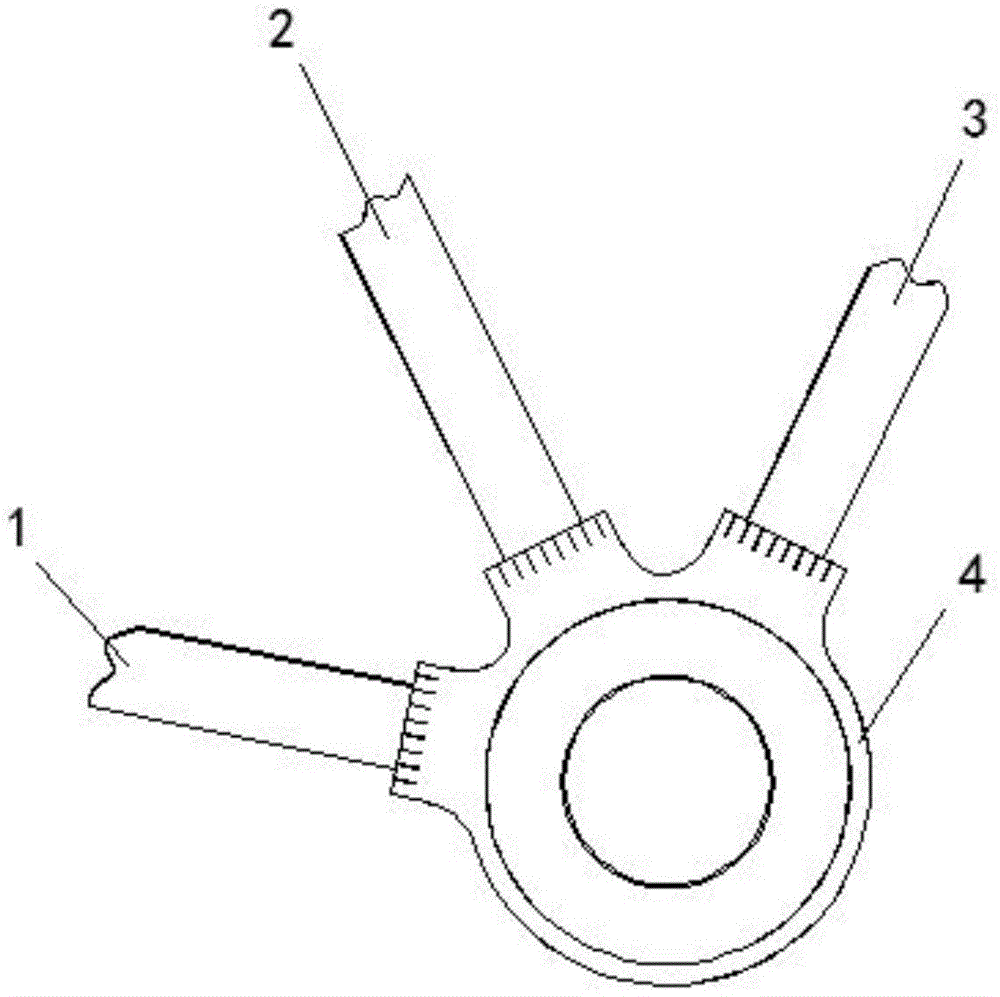
FIG. 1 is a schematic view of a drainage pipe for blocking dirt according to the present invention;
fig. 2 is a schematic sectional structure of the present invention;
FIG. 3 is a schematic view of the split structure from the drain pipe to the main body structure of the present invention;
FIG. 4 is a schematic cross-sectional view of the blowdown assembly of the present invention;
reference numerals: 1. entering a pipe; 2. a drain pipe; 3. a blow-off pipe; 4. a blowdown assembly; 41. a limiting rod; 42. a round box; 43. a spring; 44. a tube holder; 45. a sliding plug; 46. a processing chamber.
Detailed Description
In order to make the technical means, the creation features, the achievement purposes and the functions of the present invention easy to understand, the present invention will be further explained below with reference to the following embodiments and the accompanying drawings, but the following embodiments are only the preferred embodiments of the present invention, and not all embodiments are included. Based on the embodiments in the implementation, other embodiments obtained by those skilled in the art without any creative work belong to the protection scope of the present invention.
Specific embodiments of the present invention will be described below with reference to the accompanying drawings.
Example 1
As shown in fig. 1-4, a drainage pipe capable of blocking dirt comprises an inlet pipe 1, a drainage pipe 2, a sewage discharge pipe 3 and a sewage discharge assembly 4; the inlet pipe 1, the drain pipe 2 and the drain pipe 3 are arranged clockwise, are fixedly inserted in the sewage discharging assembly 4, the inlet pipe 1 is a water inlet at the joint with the sewage discharging assembly 4, the drain pipe 2 is a water outlet at the joint with the sewage discharging assembly 4, the drain pipe 3 is a sewage outlet at the joint with the sewage discharging assembly 4, and the filter block is stuffed in the end part of the drain pipe 2 facing one side of the sewage discharging assembly 4 and is used for filtering sewage.
The pollution discharge assembly 4 comprises a round box 42, a processing cavity 46 is arranged in the round box 42, a limiting rod 41 consistent with the curvature of the processing cavity 46 is arranged at the end part, back to the water inlet, of the processing cavity 46, a spring 43 is arranged in the processing cavity 46, the spring 43 is sleeved at the limiting rod 41, the spring 43 extends towards one side of the water inlet relative to the limiting rod 41, a sliding plug 45 is fixed at one end, facing the water inlet, of the spring 43, and the sliding plug 45 slides in the processing cavity 46.
The sewage discharging assembly 4 further comprises a pipe seat 44, the pipe seat 44 is arranged on the outer wall of the round box 42 in a clockwise mode and communicated with the processing cavity 46, and the inlet pipe 1, the drain pipe 2 and the sewage discharging pipe 3 are inserted into the corresponding pipe seat 44.
When the sliding plug 45 is positioned between the inlet pipe 1 and the drain pipe 2, the drain pipe 2 and the sewage discharge pipe 3 are blocked; when the sliding plug 45 is positioned between the drain pipe 2 and the sewage draining pipe 3, the sewage draining pipe 3 is blocked; when the sliding plug 45 is contacted with the limiting rod 41, the sewage discharge pipe 3 discharges sewage.
In this embodiment, during the sliding period from the sliding plug 45 to the treatment cavity 46, the sliding plug is supported by the spring 43, so that the sewage pipe 3 can be blocked within a limit, and the sewage entering the inlet pipe 2 can be filtered and discharged from the drain pipe 2.
When the accumulation amount of the dirt in the treatment cavity 46 is larger than the supporting limit of the spring 43, the sliding plug 45 moves close to the limiting rod 41 based on the water pressure effect, and during the close movement, after the sliding plug 45 touches the limiting rod 41, the blocking state of the sewage discharge pipe 3 is completely released, at the moment, the dirt can be smoothly discharged from the inside of the sewage discharge pipe 3, and the problem that the water filtering efficiency is greatly reduced due to the fact that the dirt is difficult to discharge in the treatment cavity 46 is solved.
In this embodiment, after the filth is discharged, the pressure in the pipeline drops, and the sliding plug 45 is kept away from the limiting rod 41 under the elastic force of the spring 43, so as to further block the sewage discharge pipe 3, thereby facilitating the filtering and discharging of the sewage from the water discharge pipe 2.
In the present disclosure, unless expressly stated or limited otherwise, the first feature "on" or "under" the second feature may comprise direct contact between the first and second features, or may comprise contact between the first and second features not directly. Also, the first feature being "on," "above" and "over" the second feature includes the first feature being directly on and obliquely above the second feature, or merely indicating that the first feature is at a higher level than the second feature. A first feature being "under," "below," and "beneath" a second feature includes the first feature being directly under and obliquely below the second feature, or simply meaning that the first feature is at a lesser elevation than the second feature.
The foregoing shows and describes the general principles, essential features, and advantages of the invention. It should be understood by those skilled in the art that the present invention is not limited by the above embodiments, and the description in the above embodiments and the description is only preferred examples of the present invention, and is not intended to limit the present invention, and that the present invention can have various changes and modifications without departing from the spirit and scope of the present invention, and these changes and modifications all fall into the scope of the claimed invention. The scope of the invention is defined by the appended claims and equivalents thereof.