CN215165984U - Hydraulic engineering river silt processing apparatus - Google Patents
Hydraulic engineering river silt processing apparatus Download PDFInfo
- Publication number
- CN215165984U CN215165984U CN202120873803.3U CN202120873803U CN215165984U CN 215165984 U CN215165984 U CN 215165984U CN 202120873803 U CN202120873803 U CN 202120873803U CN 215165984 U CN215165984 U CN 215165984U
- Authority
- CN
- China
- Prior art keywords
- chamber
- silt
- water
- hydraulic engineering
- preliminary treatment
- Prior art date
- Legal status (The legal status is an assumption and is not a legal conclusion. Google has not performed a legal analysis and makes no representation as to the accuracy of the status listed.)
- Active
Links
Images


Abstract
The utility model discloses a hydraulic engineering river silt processing apparatus, including handling the case, removing wheel, hybrid chamber, the chamber that catchments, preliminary treatment chamber, taking out dirty mechanism, hybrid mechanism, it installs in handling the incasement portion to remove the wheel, the preliminary treatment chamber is located handles incasement portion top, hybrid chamber and catchment chamber are located preliminary treatment chamber bottom both sides respectively, it is equipped with the filter screen to catchment between chamber and the preliminary treatment chamber, silt blanking mouth has been seted up on the hybrid chamber top. The utility model discloses a set up and take out dirty mechanism, can utilize suction pump work, thereby can utilize the sewage suction pipe to take silt out, can utilize the raceway to send the water of retrieving into the water storage tray when taking out dirty, and spout near sewage suction pipe port through high pressure nozzle, can strike near the silt of sewage suction pipe port, thereby be convenient for take silt out, avoid silt to pile up the phenomenon of being difficult for the extraction in the river course bottom, and can flow back the water of retrieving to the river course in, the water economy resource.
Description
Technical Field
The utility model relates to a hydraulic engineering correlation technique field specifically is a hydraulic engineering river silt processing apparatus.
Background
Water is a valuable resource essential to human production and life, water conservancy projects are projects constructed by controlling and allocating surface water and underground water in the nature to achieve the purposes of removing harm and benefiting, a large amount of sludge can be generated in the current water conservancy riverway, and the sludge is accumulated to easily cause riverway blockage and needs to be treated.
Current river course silt processing apparatus takes silt out in most times, but contains a large amount of pungent smell gases in the river bottom silt, directly discharges and extremely easily causes air pollution in the air, influences the health, and when extracting silt, silt in the river course leads to can't extracting because of the caking easily, influences work efficiency, needs improve.
SUMMERY OF THE UTILITY MODEL
An object of the utility model is to provide a hydraulic engineering river silt processing apparatus to solve the problem that proposes in the above-mentioned background art.
In order to achieve the above object, the utility model provides a following technical scheme: the utility model provides a hydraulic engineering river silt processing apparatus, is including handling the case, removing wheel, hybrid chamber, the chamber that catchments, preliminary treatment chamber, taking out dirty mechanism, hybrid mechanism, it installs in handling the case outside to remove the wheel, the preliminary treatment chamber is located handles incasement portion top, hybrid chamber and catchment chamber are located preliminary treatment chamber bottom both sides respectively, it is equipped with the filter screen to catchment between chamber and the preliminary treatment chamber, silt blanking mouth has been seted up on the hybrid chamber top, the preliminary treatment chamber passes through silt blanking mouth and hybrid chamber intercommunication, the drain has been seted up to the hybrid chamber bottom.
As further preferable in the present technical solution: the sewage pumping mechanism comprises a sewage suction pipe, a suction pump and a water storage disc, one end of the sewage suction pipe is communicated with the inside of the pretreatment cavity, the suction pump is installed at the top end of the treatment tank and connected with the sewage suction pipe, and the water storage disc is fixedly sleeved at one end of the sewage suction pipe.
As further preferable in the present technical solution: the water storage device is characterized in that the upper end of the water storage tray is connected with a water delivery pipe, one end of the water delivery pipe extends into the water collecting cavity and is connected with the water outlet end of the water pump, the lower surface of the water storage tray is provided with a plurality of high-pressure spray heads, and the high-pressure spray heads are uniformly distributed on the water storage tray in the circumferential direction.
As further preferable in the present technical solution: the pretreatment device is characterized in that a spiral rod is arranged in the pretreatment cavity and located at the upper end of the filter screen, a driving motor is arranged on one side wall of the treatment box, and the output end of the driving motor is fixedly connected with one end of the spiral rod.
As further preferable in the present technical solution: mixing mechanism includes stirring leaf, hollow puddler, sleeve, hollow puddler rotates and installs inside the mixing chamber, stirring leaf fixed mounting is on hollow puddler lateral wall, the sleeve rotates the cover and establishes on hollow puddler, the opening has been seted up on the part that hollow puddler is located sleeve inside.
As further preferable in the present technical solution: the treatment box is characterized in that a medicine storage box is arranged on one side wall of the treatment box, the bottom end of the medicine storage box is connected with a liquid conveying pipe, a liquid pump is arranged on the liquid conveying pipe, one end of the liquid conveying pipe is communicated with the interior of the sleeve, a plurality of liquid spraying heads are arranged on the side wall of the hollow stirring rod, and the plurality of liquid spraying heads are communicated with the interior of the hollow stirring rod.
As further preferable in the present technical solution: the top end of the hollow stirring rod extends to the inside of the pretreatment cavity and is fixedly connected with a driving bevel gear, one side of the driving bevel gear is meshed with a driven bevel gear, and the driven bevel gear is fixedly installed on the spiral rod.
The utility model provides a hydraulic engineering river silt processing apparatus possesses following beneficial effect:
(1) the utility model discloses a set up and take out dirty mechanism, can utilize suction pump work, make the intraductal negative pressure that produces of sewage suction, thereby can utilize the sewage suction pipe to take out silt, can utilize the raceway to send the water of retrieving into the water storage tray when taking out dirty, and spout near sewage suction pipe port through high pressure nozzle, can strike near the silt of sewage suction pipe port, thereby be convenient for take out silt, avoid silt to pile up the phenomenon of being difficult for the extraction in the river course bottom, and can flow back the water of retrieving to the river course in, the water economy resource.
(2) The utility model discloses a set up the mixing mechanism, can utilize the hob to rotate and drive bevel gear and rotate, thereby make drive bevel gear mesh driven bevel gear rotate, make hollow puddler rotate in step, can utilize drawing liquid pump work simultaneously, send into inside the hollow puddler with the medicament, utilize the hydrojet head on the puddler evenly to spray the medicament to the silt of mixing the intracavity, and utilize hollow puddler and stirring leaf to carry out intensive mixing reaction to medicament and silt, get rid of harmful substance and peculiar smell in the silt, then discharge through the drain, avoid it to directly discharge in the air and lead to air pollution, human health has been guaranteed to a certain extent.
Drawings
Fig. 1 is a schematic view of the overall structure of the present invention;
FIG. 2 is a schematic view of the internal structure of the present invention;
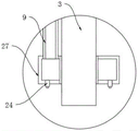
fig. 3 is a schematic structural view of a portion a in fig. 2 according to the present invention;
fig. 4 is a schematic structural diagram of a portion B in fig. 2 according to the present invention.
In the figure: 1. a treatment tank; 2. a moving wheel; 3. a sewage suction pipe; 4. a suction pump; 5. a sewage draining outlet; 6. a drug storage box; 7. a liquid pump; 8. a transfusion tube; 9. a water delivery pipe; 10. a mixing chamber; 11. a water collection cavity; 12. a pretreatment chamber; 13. a screw rod; 14. a filter screen; 15. a water pump; 16. a drive bevel gear; 17. a driven bevel gear; 18. stirring blades; 19. a liquid jet head; 20. a sludge blanking port; 21. an opening; 22. a sleeve; 23. a hollow stirring rod; 24. a high pressure spray head; 25. a dirt pumping mechanism; 26. a mixing mechanism; 27. a water storage tray; 28. the motor is driven.
Detailed Description
The technical solution in the embodiments of the present invention will be clearly and completely described below with reference to the accompanying drawings in the embodiments of the present invention.
As shown in fig. 1-4, the utility model provides a technical solution: the utility model provides a hydraulic engineering river silt processing apparatus, including handling case 1, remove wheel 2, the hybrid chamber 10, the chamber 11 that catchments, preliminary treatment chamber 12, take out dirty mechanism 25, the hybrid mechanism 26, it installs in handling case 1 outside to remove wheel 2, preliminary treatment chamber 12 is located and handles 1 inside tops of case, hybrid chamber 10 and water collection chamber 11 are located 12 bottom both sides of preliminary treatment chamber respectively, it is equipped with filter screen 14 to catchment between chamber 11 and the preliminary treatment chamber 12, silt blanking mouth 20 has been seted up on hybrid chamber 10 top, preliminary treatment chamber 12 passes through silt blanking mouth 20 and hybrid chamber 10 intercommunication, drain 5 has been seted up to hybrid chamber 10 bottom.
In this embodiment, specifically: the sewage pumping mechanism 25 comprises a sewage suction pipe 3, a suction pump 4 and a water storage disc 27, one end of the sewage suction pipe 3 is communicated with the inside of the pretreatment cavity 12, the suction pump 4 is installed at the top end of the treatment box 1 and is connected with the sewage suction pipe 3, the water storage disc 27 is fixedly sleeved at one end of the sewage suction pipe 3 and can work by utilizing the suction pump 4, so that negative pressure is generated in the sewage suction pipe 3, and sludge in a river channel can be pumped out by utilizing the sewage suction pipe 3.
In this embodiment, specifically: the water storage tray 27 upper end is connected with raceway 9, raceway 9 one end extends to the intracavity portion that catchments and is connected with water pump 15's play water end, water storage tray 27 lower surface mounting has a plurality of high pressure nozzle 24, a plurality of high pressure nozzle 24 are circumference evenly distributed on water storage tray 27, through be equipped with water storage tray 27 on sewage suction pipe 3, can utilize water pump 15 to take out the water in the intracavity portion that catchments 11 and through sending into water storage tray 27 in, can utilize a plurality of high pressure nozzle 24 on the water storage tray 27 with the water under high pressure blowout and strike near the silt of sewage suction pipe 3 port, thereby be convenient for take silt out, avoid silt to pile up the phenomenon of difficult extraction in the river course bottom, and can flow back the water of retrieving to the river course in, water economy resource.
In this embodiment, specifically: inside being equipped with the hob 13 in the preliminary treatment chamber 12, hob 13 is located filter screen 14 upper end, be equipped with driving motor 28 on the treatment tank 1 one side wall, driving motor 28's output and hob 13 one end fixed connection, when silt and water enter into preliminary treatment chamber 12 inside, can pass through filter screen 14 with the water in the silt and filter the back and collect in water collecting cavity 11, can utilize hob 13 to rotate for silt conveys to silt blanking mouth 20 and falls into in mixing chamber 10.
In this embodiment, specifically: mixing mechanism 26 includes stirring leaf 18, hollow puddler 23, sleeve 22, hollow puddler 23 rotates and installs inside mixing chamber 10, stirring leaf 18 fixed mounting is on hollow puddler 23 lateral wall, sleeve 22 rotates the cover and establishes on hollow puddler 23, hollow puddler 23 is located the part of sleeve 22 inside and has seted up opening 21, can utilize hollow puddler 23 to rotate and drive stirring leaf 18 and rotate, can stir the silt in the mixing chamber 10 when stirring leaf 18 pivoted and mix.
In this embodiment, specifically: handle and be equipped with medicine storage box 6 on 1 lateral wall of case, 6 bottom connection transfer line 8 in the medicine storage box, be equipped with drawing liquid pump 7 on the transfer line 8, 8 one end of transfer line and the inside intercommunication of sleeve 22, install a plurality of hydrojet heads 19 on the hollow puddler 23 lateral wall, a plurality of hydrojet heads 19 all communicate with hollow puddler 23 is inside, can utilize the liquid medicine in 7 extraction medicine storage box of drawing liquid pump then send into sleeve 22 through transfer line 8 in, and enter into hollow puddler 23 through opening 21 in, then spout the medicament blowout by a plurality of hydrojet heads 19, make medicament and silt intensive mixing reaction, get rid of harmful substance and peculiar smell in the silt, then discharge through drain 5, avoid it directly to discharge and lead to air pollution in the air, human health has been guaranteed to a certain extent.
In this embodiment, specifically: the top end of the hollow stirring rod 23 extends to the inside of the pretreatment cavity 12 and is fixedly connected with a driving bevel gear 16, one side of the driving bevel gear 16 is meshed with a driven bevel gear 17, the driven bevel gear 17 is fixedly installed on the screw rod 13, and the screw rod 13 can be utilized to rotate to drive the driving bevel gear 16 to rotate and be meshed with the driven bevel gear 17 to rotate, so that the hollow stirring rod 23 fixedly connected with the driven bevel gear 17 synchronously rotates to stir and mix.
It should be noted that, a hydraulic engineering river channel sludge treatment device, when working, can utilize the suction pump 4 to work, thus make the interior of the sewage suction pipe 3 produce the negative pressure, can utilize the sewage suction pipe 3 to extract the sludge in the river channel, the extracted sludge and water are sent into the pretreatment cavity 12, when the sludge and water enter into the pretreatment cavity 12, the water in the sludge can be collected in the water collection cavity 11 after being filtered by the filter screen 14, at the same time, the water in the water collection cavity 11 can be extracted by the water pump 15 and sent into the water storage tray 27 by the conduit pipe 9, the high pressure water can be sprayed out by the plurality of high pressure nozzles 24 on the water storage tray 27 and impact the sludge near the port of the sewage suction pipe 3, thus the sludge can be extracted conveniently, the phenomenon that the sludge is piled up at the bottom of the river channel and is not easy to be extracted can be avoided, and the recovered water can flow back to the river channel, the water resource is saved, the screw rod 13 can be utilized to rotate, make silt convey to silt blanking mouth 20 and fall into in the hybrid chamber 10, can utilize hob 13 to rotate and drive bevel gear 16 and rotate and mesh driven bevel gear 17 and rotate, thereby make and stir the mixing operation with driven bevel gear 17 fixed connection's hollow puddler 23 synchronous revolution, can utilize the liquid medicine in the drawing medicine storage box 6 of drawing liquid pump 7 then send into sleeve 22 through transfer line 8 in, and enter into hollow puddler 23 through opening 21 in, then spout the medicament by a plurality of hydrojet heads 19, make medicament and silt intensive mixing reaction, get rid of harmful substance and peculiar smell in the silt, then discharge through drain 5, avoid it directly to discharge in the air and lead to air pollution, human health has been guaranteed to a certain extent, guarantee that the treatment effect is good, and convenient to use.
Although embodiments of the present invention have been shown and described, it will be appreciated by those skilled in the art that changes, modifications, substitutions and alterations can be made in these embodiments without departing from the principles and spirit of the invention, the scope of which is defined in the appended claims and their equivalents.
Claims (7)
1. The utility model provides a hydraulic engineering river course silt processing apparatus, its characterized in that, is including handling case (1), removing wheel (2), hybrid chamber (10), chamber (11), preliminary treatment chamber (12), taking out dirty mechanism (25), hybrid mechanism (26), it installs in handling case (1) outside to remove wheel (2), preliminary treatment chamber (12) are located the inside top of handling case (1), hybrid chamber (10) and water collection chamber (11) are located preliminary treatment chamber (12) bottom both sides respectively, it is equipped with filter screen (14) to catchment between chamber (11) and preliminary treatment chamber (12), silt blanking mouth (20) have been seted up on hybrid chamber (10) top, preliminary treatment chamber (12) are through silt blanking mouth (20) and hybrid chamber (10) intercommunication, drain (5) have been seted up to hybrid chamber (10) bottom.
2. The hydraulic engineering river sludge treatment device according to claim 1, wherein: the sewage pumping mechanism (25) comprises a sewage suction pipe (3), a suction pump (4) and a water storage disc (27), one end of the sewage suction pipe (3) is communicated with the interior of the pretreatment cavity (12), the suction pump (4) is installed on the top of the treatment box (1) and is connected with the sewage suction pipe (3), and the water storage disc (27) is fixedly sleeved at one end of the sewage suction pipe (3).
3. The hydraulic engineering river sludge treatment device according to claim 2, wherein: the water storage device is characterized in that the upper end of the water storage tray (27) is connected with a water delivery pipe (9), one end of the water delivery pipe (9) extends into the water collection cavity (11) and is connected with the water outlet end of the water pump (15), a plurality of high-pressure spray heads (24) are arranged on the lower surface of the water storage tray (27), and the high-pressure spray heads (24) are circumferentially and uniformly distributed on the water storage tray (27).
4. The hydraulic engineering river sludge treatment device according to claim 1, wherein: the pretreatment chamber (12) is inside to be equipped with hob (13), hob (13) are located filter screen (14) upper end, be equipped with driving motor (28) on handling case (1) a lateral wall, the output and hob (13) one end fixed connection of driving motor (28).
5. The hydraulic engineering river sludge treatment device according to claim 1, wherein: mixing mechanism (26) are including stirring leaf (18), hollow puddler (23), sleeve (22), hollow puddler (23) are rotated and are installed inside mixing chamber (10), stirring leaf (18) fixed mounting is on hollow puddler (23) lateral wall, sleeve (22) are rotated the cover and are established on hollow puddler (23), opening (21) have been seted up on hollow puddler (23) are located the inside part of sleeve (22).
6. The hydraulic engineering river sludge treatment device according to claim 5, wherein: handle and be equipped with medicine storage box (6) on case (1) a lateral wall, transfer line (8) are connected to medicine storage box (6) bottom, be equipped with drawing liquid pump (7) on transfer line (8), transfer line (8) one end and sleeve (22) inside intercommunication, install a plurality of hydrojet heads (19) on hollow puddler (23) lateral wall, it is a plurality of hydrojet head (19) all communicate with hollow puddler (23) inside.
7. The hydraulic engineering river sludge treatment device according to claim 6, wherein: the top end of the hollow stirring rod (23) extends to the inside of the pretreatment cavity (12) and is fixedly connected with a driving bevel gear (16), one side of the driving bevel gear (16) is connected with a driven bevel gear (17) in a meshed mode, and the driven bevel gear (17) is fixedly installed on the spiral rod (13).
Priority Applications (1)
| Application Number | Priority Date | Filing Date | Title |
|---|---|---|---|
| CN202120873803.3U CN215165984U (en) | 2021-04-26 | 2021-04-26 | Hydraulic engineering river silt processing apparatus |
Applications Claiming Priority (1)
| Application Number | Priority Date | Filing Date | Title |
|---|---|---|---|
| CN202120873803.3U CN215165984U (en) | 2021-04-26 | 2021-04-26 | Hydraulic engineering river silt processing apparatus |
Publications (1)
| Publication Number | Publication Date |
|---|---|
| CN215165984U true CN215165984U (en) | 2021-12-14 |
Family
ID=79363970
Family Applications (1)
| Application Number | Title | Priority Date | Filing Date |
|---|---|---|---|
| CN202120873803.3U Active CN215165984U (en) | 2021-04-26 | 2021-04-26 | Hydraulic engineering river silt processing apparatus |
Country Status (1)
| Country | Link |
|---|---|
| CN (1) | CN215165984U (en) |
Cited By (1)
| Publication number | Priority date | Publication date | Assignee | Title |
|---|---|---|---|---|
| CN117401738A (en) * | 2023-10-19 | 2024-01-16 | 江苏中矩环保科技有限公司 | Environment-friendly water treatment dosing system and method |
-
2021
- 2021-04-26 CN CN202120873803.3U patent/CN215165984U/en active Active
Cited By (1)
| Publication number | Priority date | Publication date | Assignee | Title |
|---|---|---|---|---|
| CN117401738A (en) * | 2023-10-19 | 2024-01-16 | 江苏中矩环保科技有限公司 | Environment-friendly water treatment dosing system and method |
Similar Documents
| Publication | Publication Date | Title |
|---|---|---|
| CN210874719U (en) | Multiple treatment device for garbage classification | |
| CN215165984U (en) | Hydraulic engineering river silt processing apparatus | |
| CN204918021U (en) | Mechanism is got rid of to foam oil slick | |
| CN219662929U (en) | Anti-floating structure of extraction tank | |
| CN210543566U (en) | Residue separation and filtration device for fracturing flow-back fluid treatment | |
| CN204051163U (en) | A kind of sewage filter device | |
| CN213049485U (en) | It is biological with multi-functional jar that draws | |
| CN213467220U (en) | High-efficient filtration purification case that sprays | |
| CN210683335U (en) | Kitchen waste water fermentation removes dross device | |
| CN211646204U (en) | Rolling slag remover | |
| CN213160056U (en) | Waste incineration tail gas treatment device for environmental protection | |
| CN213771751U (en) | Integrated sewage treatment equipment based on improved AO technology and membrane technology | |
| CN211056841U (en) | Remove emergent rubbish penetrant treatment facility | |
| CN209024370U (en) | A kind of Ecological water environment processing system | |
| CN218339394U (en) | Environment-friendly flue gas treatment spray tower | |
| CN212457981U (en) | Fine powder recovery device for kiln tail dust collector | |
| CN220513818U (en) | Spray tower for chemical tail gas treatment | |
| CN217887250U (en) | A prevent blockking up waste water filtration equipment for plant | |
| CN212214695U (en) | Sediment cleaning device for sewage treatment | |
| CN217377560U (en) | Leachate purification treatment device | |
| CN216726495U (en) | Dust conveyor for dust removal | |
| CN204602748U (en) | A kind of fuel tank cleaner | |
| CN213141765U (en) | Sludge discharge device for sewage treatment | |
| CN215391406U (en) | Steel solid waste processing apparatus convenient to remove dust | |
| CN219072333U (en) | Leaching liquid extraction separation device |
Legal Events
| Date | Code | Title | Description |
|---|---|---|---|
| GR01 | Patent grant | ||
| GR01 | Patent grant |