CN215071195U - Photovoltaic power distribution cabinet for photovoltaic power station - Google Patents
Photovoltaic power distribution cabinet for photovoltaic power station Download PDFInfo
- Publication number
- CN215071195U CN215071195U CN202022435255.4U CN202022435255U CN215071195U CN 215071195 U CN215071195 U CN 215071195U CN 202022435255 U CN202022435255 U CN 202022435255U CN 215071195 U CN215071195 U CN 215071195U
- Authority
- CN
- China
- Prior art keywords
- photovoltaic power
- cavity
- distribution cabinet
- power distribution
- chamber
- Prior art date
- Legal status (The legal status is an assumption and is not a legal conclusion. Google has not performed a legal analysis and makes no representation as to the accuracy of the status listed.)
- Active
Links
Images


Abstract
The utility model relates to a photovoltaic power distribution cabinet used in a photovoltaic power station, which comprises a photovoltaic power generation board, a power distribution cabinet main body, an air heater, a lightning arrester, a heat insulation board, a balancing weight and a cabinet door, the power distribution cabinet main body is of a cuboid structure and comprises an upper cavity chamber, a middle cavity chamber and a lower cavity chamber, the photovoltaic power generation board is supported at the top end of the upper chamber, the bottom surface of the upper chamber is provided with a mounting hole, an air heater is arranged at the mounting hole, the bottom end of the lower chamber is provided with a balancing weight, a dustproof net is arranged between the middle chamber and the lower chamber, the middle chamber and the lower chamber are of a communicated structure, the peripheral side surface of the lower cavity is uniformly provided with vent holes, the inner sides of the four walls of the middle cavity are provided with heat insulation boards, the area of the heat insulation plates arranged on the four walls of the middle chamber is equal to that of the wall where the heat insulation plates are arranged, the side face of the upper chamber is provided with a lightning arrester, and the middle chamber is provided with a cabinet door. The utility model discloses the effectual problem of having solved photovoltaic switch board heat protection, heat dissipation, dehumidification.
Description
Technical Field
The utility model relates to a photovoltaic power distribution cabinet, in particular to photovoltaic power generation station uses photovoltaic power distribution cabinet.
Background
The photovoltaic power generation station is for guaranteeing sufficient solar energy, usually all can select in the great region of sunshine volume, the time that the switch board received sunshine to shine is longer, the temperature of watchcase is higher, influence each other with the heat that its inside electrical component produced for the inside temperature of switch board sharply rises, the heat dissipation problem becomes especially important, traditional natural draft mode radiating efficiency is low, and it is great again to the energy consumption with the help of heat abstractor, because the photovoltaic switch board sets up outdoors, so except that the heat dissipation dampproofing problem also is the priority.
Therefore, in view of the current situation, it is urgently needed to develop a photovoltaic power distribution cabinet for a photovoltaic power station so as to meet the needs of actual use.
SUMMERY OF THE UTILITY MODEL
To the not enough that exists on the prior art, the utility model provides a photovoltaic power generation station uses photovoltaic switch board, the utility model discloses the principle is simple, and heat protection, heat dissipation, dehumidification effect are obvious. In order to achieve the above purpose, the present invention is realized by the following technical solution:
a photovoltaic power distribution cabinet for a photovoltaic power station comprises a photovoltaic power generation board, a power distribution cabinet main body, a hot air blower, a humidity sensor, a control switch, a lightning arrester, a heat insulation board, a balancing weight and a cabinet door, wherein the power distribution cabinet main body is of a cuboid structure, the power distribution cabinet main body comprises an upper cavity, a middle cavity and a lower cavity, the top of the upper cavity is of a structure communicated with the outside, four equal-length supporting columns are upwards extended from four corners of the top surface of the upper cavity, the top ends of the supporting columns support the photovoltaic power generation board, four side surfaces of the upper cavity upwards extend to be connected with the photovoltaic power generation board through a dust screen, the bottom surface of the upper cavity is provided with mounting holes, the hot air blower is arranged at the mounting holes, the axis direction of the hot air blower is vertical to the ground, the hot air blower is electrically connected with a weak circuit in an electric room, four equal-length supporting columns downwards extend from four corners of the bottom surface of the lower cavity, and positioning blocks are arranged on the supporting column surfaces, the locating piece is connected with the balancing weight through the bolt, cavity and cavity down are the UNICOM structure in the middle of being equipped with the dust screen between middle cavity and the lower cavity, side equipartition ventilation hole around the cavity down, the heat insulating board has been installed to middle cavity four walls inboard, the heat insulating board area that middle cavity four walls were installed equals with place wall area, lightning arrester includes that one of them pillar in four pillars by last cavity top surface transversely extends a columnar structure and lightning rod, the columnar structure extends to beyond the vertical decurrent cover face of photovoltaic power generation board, the lightning rod is installed in the columnar structure one end of keeping away from the switch board, middle cavity is equipped with cabinet door and middle cavity articulated, elastic sand grip is all established to one side four sides that middle cavity was equipped with the cabinet door.
Preferably, the air heater is electrically connected with the humidity sensor and the control switch.
Preferably, at least 2 positioning holes are uniformly distributed in the positioning block, the axis direction of each positioning hole is perpendicular to the ground, and positioning holes are formed in the upper end face of the balancing weight and the positions, corresponding to the positioning holes, of the positioning block.
Preferably, the lightning rod is electrically connected with four pillars on the bottom surface of the lower chamber.
Preferably, the axial direction of the elastic convex strip is parallel to the direction of the edge.
Preferably, the inner side of the cabinet door is provided with a heat insulation plate, and the area of the heat insulation plate arranged on the inner side of the cabinet door is equal to the area of the door frame corresponding to the cabinet door.
Drawings
The present invention will be described in detail with reference to the accompanying drawings and specific embodiments.
FIG. 1 is a schematic side view of the present invention;
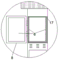
FIG. 2 is a schematic front view of the present invention;
fig. 3 is an external schematic view of the middle chamber of the present invention.
Detailed Description
In order to make the technical means, creation features, achievement purposes and functions of the present invention easy to understand, the present invention is further described below with reference to the following embodiments.
The utility model provides a photovoltaic switch board that photovoltaic power generation station used which characterized in that: the power distribution cabinet comprises a photovoltaic power generation plate 1, a power distribution cabinet main body 2, an air heater 3, a humidity sensor 4, a control switch 5, a lightning arrester, a heat insulation plate 6, a balancing weight 7 and a cabinet door 8, wherein the power distribution cabinet main body 2 is of a cuboid structure, the power distribution cabinet main body comprises an upper cavity 201, a middle cavity 202 and a lower cavity 203, the top of the upper cavity 201 is of a structure communicated with the outside, four equal-length pillars 9 are upwards extended from four corners of the top surface of the upper cavity, the top end of each pillar 9 supports the photovoltaic power generation plate 1, four side surfaces of the upper cavity upwards extend to be connected with the photovoltaic power generation plate through a dust screen 10, the bottom surface of the upper cavity is provided with a mounting hole, the air heater 3 is installed at the mounting hole, the axis direction of the air heater 3 is vertical to the ground, the air heater 3 is electrically connected with a weak circuit in an electric room, the four corners of the bottom surface of the lower cavity 203 downwards extend to four equal-length pillars 11, and the bottom end surfaces of the pillars 11 are provided with positioning blocks 12, the positioning block 12 is connected with the counterweight block 7 through a bolt, a dustproof net 13 is arranged between the middle chamber 202 and the lower chamber 203, the middle chamber and the lower chamber are in a communicated structure, the peripheral side surface of the lower chamber is uniformly provided with vent holes 14, the inner sides of the four walls of the middle chamber are provided with heat insulation 6 plates, the area of the heat insulation board 6 arranged on the four walls of the middle chamber is equal to the area of the wall, the lightning arrester comprises a columnar structure 15 and a lightning rod 16 which transversely extend from one of four pillars 9 on the top surface of the upper chamber 201, the columnar structure 15 extends out of the vertical downward covering surface of the photovoltaic power generation panel 1, the lightning rod 16 is arranged at one end of the columnar structure 15 far away from the power distribution cabinet, middle cavity 202 is equipped with cabinet door 8 and cabinet door 8 is articulated with middle cavity 202, elastic convex strip 17 is all established to one side four sides that middle cavity 202 was equipped with cabinet door 8.
In the above embodiment, the humidity sensor 4 of the air heater 3 is electrically connected to the control switch 5.
In the above embodiment, at least 2 positioning holes are uniformly distributed on the positioning block 12, the axis direction of the positioning holes is perpendicular to the ground, and the positioning holes are arranged at the positions of the upper end surface of the counterweight block 7 corresponding to the positioning holes on the positioning block.
In the above example, the lightning rod 16 is electrically connected to the four pillars 11 on the bottom surface of the lower chamber 203.
In the above example, the axial direction of the elastic ribs 17 is parallel to the direction of the side.
In the above embodiment, the heat insulation board 6 is installed inside the cabinet door 8, and the area of the heat insulation board 6 installed inside the cabinet door 8 is equal to the area of the door frame corresponding to the cabinet door.
In the concrete implementation of the method, the method comprises the following steps:
because the utility model is placed in the place where the sunlight is sufficient, the heat absorbed by the outer surface of the utility model is effectively isolated by the heat insulation board 6 arranged in the interior, the side surface of the lower chamber 203 and the top surface of the upper chamber 201 of the utility model are both ventilation structures, which can efficiently dissipate heat, because the utility model is arranged outdoors and is in a communication structure with the outside, the moisture can be larger sometimes, the humidity sensor 4 detects the humidity in the utility model in real time, when the humidity is larger, the communication control switch is the hot air blower to dry when the humidity is larger, the hot air blower stops working after the humidity drops to a certain value, the elastic convex strip 17 between the cabinet door 8 and the door frame of the utility model effectively prevents the dust from entering when the transverse wind is blown, the upper chamber 201 mainly prevents the hot air blower 3 from raining, the dust screen at the top of the four walls of the upper chamber 203 prevents the entering of the external objects, the lightning arrester effectively prevents the circuit from being damaged by lightning stroke, lower half section of four spinal branch posts 11 of cavity 203 bottom surface is together buried underground with balancing weight 7 down, has not only proved the utility model discloses a firm and can also be through lightning rod 16 with the thunder and lightning guide underground when meetting the thunderbolt.
The utility model discloses the principle is simple, and heat protection, heat dissipation, dehumidification effect are obvious.
Those skilled in the art should understand that the present invention is not limited by the above embodiments. The foregoing embodiments and description have been made only for the purpose of illustrating the principles of the invention. The present invention can be further modified and improved without departing from the spirit and scope of the present invention. Such changes and modifications are intended to be within the scope of the claimed invention. The scope of the invention is defined by the appended claims and equivalents thereof.
Claims (6)
1. The utility model provides a photovoltaic switch board that photovoltaic power generation station used which characterized in that: the power distribution cabinet comprises a photovoltaic power generation board, a power distribution cabinet main body, an air heater, a humidity sensor, a control switch, a lightning arrester, a heat insulation board, a balancing weight and a cabinet door, wherein the power distribution cabinet main body is of a cuboid structure, the power distribution cabinet main body comprises an upper cavity, a middle cavity and a lower cavity, the top of the upper cavity is of a structure communicated with the outside, four equal-length pillars are upwards extended from four corners of the top surface of the upper cavity, the top ends of the pillars are supported by the photovoltaic power generation board, four side surfaces of the upper cavity are upwards extended to be connected with the photovoltaic power generation board through a dust screen, the bottom surface of the upper cavity is provided with mounting holes, the air heater is arranged at the mounting holes, the axis direction of the air heater is perpendicular to the ground, the air heater is electrically connected with a weak circuit in an electric room, four equal-length pillars are downwards extended from four corners of the bottom surface of the lower cavity, and positioning blocks are arranged on the bottom surfaces of the pillars, the locating piece is connected with the balancing weight through the bolt, cavity and cavity down are the UNICOM structure in the middle of being equipped with the dust screen between middle cavity and the lower cavity, side equipartition ventilation hole around the cavity down, the heat insulating board has been installed to middle cavity four walls inboard, the heat insulating board area that middle cavity four walls were installed equals with place wall area, lightning arrester includes that one of them pillar in four pillars by last cavity top surface transversely extends a columnar structure and lightning rod, the columnar structure extends to beyond the vertical decurrent cover face of photovoltaic power generation board, the lightning rod is installed in the columnar structure one end of keeping away from the switch board, middle cavity is equipped with cabinet door and middle cavity articulated, elastic sand grip is all established to one side four sides that middle cavity was equipped with the cabinet door.
2. The photovoltaic power distribution cabinet for the photovoltaic power station as recited in claim 1, wherein the air heater is electrically connected with the humidity sensor and the control switch.
3. The photovoltaic power distribution cabinet for the photovoltaic power station as claimed in claim 1, wherein at least 2 positioning holes are uniformly distributed on the positioning block, the axial direction of the positioning holes is perpendicular to the ground, and the positioning holes are arranged on the upper end surface of the counterweight block and in positions corresponding to the positioning holes on the positioning block.
4. The photovoltaic power distribution cabinet for the photovoltaic power plant according to claim 1, wherein the lightning rod is electrically connected with four pillars on the bottom surface of the lower chamber.
5. The photovoltaic power distribution cabinet for the photovoltaic power station as claimed in claim 1, wherein the axis direction of the elastic ribs is parallel to the direction of the edges.
6. The photovoltaic power distribution cabinet for the photovoltaic power station as recited in claim 1, wherein a thermal insulation board is installed inside the cabinet door, and the area of the thermal insulation board installed inside the cabinet door is equal to the area of the door frame corresponding to the cabinet door.
Priority Applications (1)
| Application Number | Priority Date | Filing Date | Title |
|---|---|---|---|
| CN202022435255.4U CN215071195U (en) | 2020-10-28 | 2020-10-28 | Photovoltaic power distribution cabinet for photovoltaic power station |
Applications Claiming Priority (1)
| Application Number | Priority Date | Filing Date | Title |
|---|---|---|---|
| CN202022435255.4U CN215071195U (en) | 2020-10-28 | 2020-10-28 | Photovoltaic power distribution cabinet for photovoltaic power station |
Publications (1)
| Publication Number | Publication Date |
|---|---|
| CN215071195U true CN215071195U (en) | 2021-12-07 |
Family
ID=79160397
Family Applications (1)
| Application Number | Title | Priority Date | Filing Date |
|---|---|---|---|
| CN202022435255.4U Active CN215071195U (en) | 2020-10-28 | 2020-10-28 | Photovoltaic power distribution cabinet for photovoltaic power station |
Country Status (1)
| Country | Link |
|---|---|
| CN (1) | CN215071195U (en) |
-
2020
- 2020-10-28 CN CN202022435255.4U patent/CN215071195U/en active Active
Similar Documents
| Publication | Publication Date | Title |
|---|---|---|
| CN209249989U (en) | A kind of distribution box for low-voltage complete switch equipment | |
| CN110891386A (en) | Outdoor integrated cabinet for 5G base station | |
| CN211605832U (en) | Outdoor rainproof and snow-proof distribution box | |
| CN104393512A (en) | Novel power equipment box | |
| CN203243639U (en) | Improved structure of outdoor electronic equipment cabinet | |
| CN210093750U (en) | Dampproofing dust removal regulator cubicle | |
| CN207200037U (en) | One kind has antistatic and heat sinking function power equipment case | |
| CN215071195U (en) | Photovoltaic power distribution cabinet for photovoltaic power station | |
| CN205960439U (en) | Moistureproof dehumidification electric power cabinet | |
| CN108590256B (en) | Distribution room with cooling and dehumidifying functions | |
| CN208241151U (en) | Electrical equipment energy saver | |
| CN213401995U (en) | Outdoor power distribution cabinet | |
| CN211456428U (en) | Intelligent high-voltage board of dampproofing function dispels heat | |
| CN213367224U (en) | Power distribution cabinet body with good protection effect | |
| CN209929989U (en) | Grid-connected booster station | |
| CN212627435U (en) | High-rotation-speed brushless DC motor | |
| CN210111310U (en) | High-voltage ring main unit | |
| CN210326588U (en) | Outdoor distribution box with antistatic insulating shell | |
| CN209963603U (en) | Block terminal with heat dissipation function | |
| CN209805201U (en) | High-low pressure complete equipment cabinet structure | |
| CN209805116U (en) | Waterproof incoming line cabinet | |
| CN215497615U (en) | Power transmission and distribution equipment with lightning protection function | |
| CN207743588U (en) | A kind of outdoor power construction easy to maintenance rain-proof anticollision distribution box | |
| CN107733331B (en) | A kind of photovoltaic electrification component with a variety of use states | |
| CN207053011U (en) | A kind of transformer station damp-proof rack |
Legal Events
| Date | Code | Title | Description |
|---|---|---|---|
| GR01 | Patent grant | ||
| GR01 | Patent grant | ||
| CP02 | Change in the address of a patent holder |
Address after: 453000 No. D3, floor 3, unit D, building 5, No. 11, Changchun Road, high tech Industrial Development Zone, Zhengzhou City, Henan Province Patentee after: Henan dianhousekeeper power supply service Co.,Ltd. Address before: 453000 No. 111, zone a, 1f, No. 166, Xindong Avenue, Hongqi District, Xinxiang City, Henan Province Patentee before: Henan dianhousekeeper power supply service Co.,Ltd. |
|
| CP02 | Change in the address of a patent holder |