CN215060140U - Non-excavation modified polyethylene internal energy protective sleeve of plugging structure - Google Patents
Non-excavation modified polyethylene internal energy protective sleeve of plugging structure Download PDFInfo
- Publication number
- CN215060140U CN215060140U CN202121279680.7U CN202121279680U CN215060140U CN 215060140 U CN215060140 U CN 215060140U CN 202121279680 U CN202121279680 U CN 202121279680U CN 215060140 U CN215060140 U CN 215060140U
- Authority
- CN
- China
- Prior art keywords
- pipeline body
- modified polyethylene
- internal energy
- plug
- groove
- Prior art date
- Legal status (The legal status is an assumption and is not a legal conclusion. Google has not performed a legal analysis and makes no representation as to the accuracy of the status listed.)
- Active
Links
Images


Landscapes
- Laying Of Electric Cables Or Lines Outside (AREA)
Abstract
The utility model discloses a non-excavation modified polyethylene internal energy protecting pipe of block structure, including the pipeline body, its characterized in that: the pipeline body is provided with a plug, the plug is provided with a clamping jaw, and the pipeline body is provided with a rotary groove and a clamping groove which are matched with the clamping jaw; the utility model discloses install the end cap on the pipeline body, can play the effect of shutoff to the pipeline body at the in-process of transportation, can effectually avoid rainwater and moisture to the erosion of pipeline inner wall, reach the purpose of protection pipeline inner wall.
Description
[ technical field ] A method for producing a semiconductor device
The utility model relates to the technical field of pipelines, specifically indicate a non-excavation modified polyethylene internal energy protecting pipe of block structure.
[ background of the invention ]
The polyethylene pipe is divided into excavation and non-excavation, the non-excavation refers to a new construction technology for laying, replacing and repairing various underground pipelines by utilizing various rock-soil drilling equipment and technical means under the condition of excavating a tiny part of the earth surface (generally referring to small-area excavation of an inlet and an outlet) in the modes of guiding, directional drilling and the like, the traffic cannot be obstructed, green lands and vegetations cannot be damaged, the normal life and working order of shops, hospitals, schools and residents cannot be influenced, the interference of the traditional excavation construction on the life of the residents is solved, and the damage and the adverse effect on the traffic, the environment and the foundation of surrounding buildings are avoided, so that the high social and economic effects are achieved. In the conventional pipeline transportation process, pipelines are usually stacked on a truck for transportation, but the pipelines are influenced by rainwater and moisture in the transportation process, rainwater can be deposited on the inner walls of the pipelines, and the inner walls of the pipelines are corroded. Therefore, the trenchless modified polyethylene internal energy protective sleeve of the plugging structure is provided.
[ Utility model ] content
The utility model aims at solving the in-process of the pipe transportation of system, piling up the pipeline usually and transporting on the freight train, but receive the influence of rainwater and moisture at the in-process of transportation, can appear the deposit of rainwater at the pipe inner wall, cause the problem to the erosion of pipe inner wall and propose a block structure's non-excavation modified polyethylene internal energy protecting pipe.
In order to achieve the above purpose, the utility model provides a following technical scheme: the utility model provides a non-excavation modified polyethylene internal energy protecting pipe of block structure, includes pipeline body, its characterized in that: the pipeline is characterized in that a plug is installed on the pipeline body, a clamping jaw is arranged on the plug, and a rotary groove and a clamping groove matched with the clamping jaw are formed in the pipeline body.
Further preferred is: the two sides of the clamping jaw are of inclined structures.
Further preferred is: the pipe fitting is characterized in that a sealing ring mounting groove is formed in the plug, a sealing ring is mounted in the sealing ring mounting groove, a limiting groove matched with the sealing ring is formed in the pipe body, and the plug is sealed with the pipe body through the sealing ring.
Further preferred is: the plug is also provided with a plurality of grooves.
The utility model has the advantages that:
the utility model discloses install the end cap on the pipeline body, can play the effect of shutoff to the pipeline body at the in-process of transportation, can effectually avoid rainwater and moisture to the erosion of pipeline inner wall, reach the purpose of protection pipeline inner wall.
[ description of the drawings ]
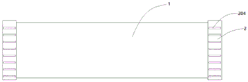
FIG. 1 is a schematic structural diagram of the present invention;
FIG. 2 is a schematic view of a part of the structure of the present invention;
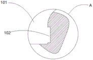
FIG. 3 is an enlarged view at A of FIG. 2;
FIG. 4 is a schematic view of a pipe body construction;
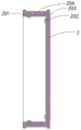
fig. 5 is a schematic structural view of the plug.
Fig. 6 is a schematic cross-sectional view of a plug.
Illustration of the drawings: 1. a pipe body; 101. a rotating tank; 102. a card slot; 103. a limiting groove; 2. a plug; 201. a claw; 2011. a tilt structure; 202. a sealing ring mounting groove; 203. a seal ring; 204. and (4) a groove.
Detailed Description
The trenchless modified polyethylene internal energy sheath of the plugging structure of the present invention will be further described with reference to fig. 1 to 5.
Referring to the attached drawings 1-6, the trenchless modified polyethylene internal energy sheath pipe of the plugging structure of the embodiment comprises a pipe body 1, and is characterized in that: the pipeline comprises a pipeline body 1 and is characterized in that a plug 2 is installed on the pipeline body 1, a clamping jaw 201 is arranged on the plug 2, and a rotary groove 101 and a clamping groove 102 which are matched with the clamping jaw 201 are formed in the pipeline body 1; through the setting of the rotating groove 101, the effect of guiding can be played to the installation of the clamping jaw 201, and meanwhile, the clamping groove 102 and the clamping jaw 201 are matched and buckled to be connected, so that the plug 2 can be fixed on the pipeline body 1
Referring to fig. 5, the two sides of the claw 201 are provided with inclined structures 2011; through the arrangement of the inclined structures 2011 on two sides, the clamping groove 102 can be conveniently screwed into the clamping groove 102 from the rotary groove 101 and screwed out of the clamping groove 102 from the clamping groove 102 while the clamping groove 102 and the clamping jaw 201 are not influenced to be matched and buckled, and the situation that the clamping is hard to move is avoided.
Referring to fig. 4 to 6, a sealing ring installation groove 202 is formed in the plug 2, a sealing ring 203 is fixedly installed in the sealing ring installation groove 202, a limiting groove 103 matched with the sealing ring 203 is formed in the pipeline body 1, and the plug 2 is sealed with the pipeline body 1 through the sealing ring 203.
Referring to fig. 1, a plurality of grooves 204 are further formed on the plug 2; through the setting of recess 204, can play the effect of increase friction power at the in-process of rotatory end cap 2 to be convenient for rotate end cap 2, avoid appearing the condition of end cap 2 slippage.
The utility model discloses a use as follows, at first through rotatory groove 101, screw in the jack catch 201 on end cap 2 in draw-in groove 102, through the cooperation buckle connection of draw-in groove 102 and jack catch 201, fix end cap 2 on pipeline body 1, and through the setting of sealing washer 203, can play the sealed effect of pipeline body 1 and end cap 2, avoid in the transportation, rainwater and moisture get into the pipeline in, corrode the pipeline inner wall; when end cap 2 needs to be detached, end cap 2 rotates reversely, and due to the fact that the clamping jaw 201 can be conveniently screwed out from the clamping groove 102 through the arrangement of the inclined structure 2011 on the clamping jaw 201, the situation that the clamping jaw can not be screwed out is avoided, and meanwhile friction force of end cap 2 can be increased due to the groove 204 arranged on end cap 2, so that the purpose of conveniently rotating end cap 2 is achieved.
The above-mentioned embodiment is right the utility model discloses an explanation, it is not right the utility model discloses a limited, any right the scheme after the simple transform of the utility model all belongs to the protection scope of the utility model.
Claims (4)
1. The utility model provides a capping structure's modified polyethylene internal energy sheath of non-excavation, includes pipeline body (1), its characterized in that: install end cap (2) on pipeline body (1), be provided with jack catch (201) on end cap (2), be provided with on pipeline body (1) with jack catch (201) looks adaptation's rotatory groove (101) and draw-in groove (102).
2. The trenchless modified polyethylene internal energy sheath pipe of the plugging structure of claim 1, wherein: the two sides of the clamping jaw (201) are inclined structures (2011).
3. The trenchless modified polyethylene internal energy sheath pipe of the plugging structure of claim 1, wherein: the pipeline sealing structure is characterized in that a sealing ring mounting groove (202) is formed in the plug (2), a sealing ring (203) is mounted in the sealing ring mounting groove (202), a limiting groove (103) matched with the sealing ring (203) is formed in the pipeline body (1), and the plug (2) is sealed with the pipeline body (1) through the sealing ring (203).
4. The trenchless modified polyethylene internal energy sheath pipe of the plugging structure of claim 3, wherein: the plug (2) is also provided with a plurality of grooves (204).
Priority Applications (1)
| Application Number | Priority Date | Filing Date | Title |
|---|---|---|---|
| CN202121279680.7U CN215060140U (en) | 2021-06-09 | 2021-06-09 | Non-excavation modified polyethylene internal energy protective sleeve of plugging structure |
Applications Claiming Priority (1)
| Application Number | Priority Date | Filing Date | Title |
|---|---|---|---|
| CN202121279680.7U CN215060140U (en) | 2021-06-09 | 2021-06-09 | Non-excavation modified polyethylene internal energy protective sleeve of plugging structure |
Publications (1)
| Publication Number | Publication Date |
|---|---|
| CN215060140U true CN215060140U (en) | 2021-12-07 |
Family
ID=79204856
Family Applications (1)
| Application Number | Title | Priority Date | Filing Date |
|---|---|---|---|
| CN202121279680.7U Active CN215060140U (en) | 2021-06-09 | 2021-06-09 | Non-excavation modified polyethylene internal energy protective sleeve of plugging structure |
Country Status (1)
| Country | Link |
|---|---|
| CN (1) | CN215060140U (en) |
-
2021
- 2021-06-09 CN CN202121279680.7U patent/CN215060140U/en active Active
Similar Documents
| Publication | Publication Date | Title |
|---|---|---|
| CN102561977B (en) | High-pressure high-flow water burst hole drilling safety system, mounting process thereof and service process | |
| CN101463924A (en) | Heavy caliber pipe-jacking butt joint technique | |
| CN203585040U (en) | Foundation bolt protective cover | |
| CN201149984Y (en) | Sealing plugging structure for cable hole | |
| CN215060140U (en) | Non-excavation modified polyethylene internal energy protective sleeve of plugging structure | |
| CN201606566U (en) | Top pipe injection device | |
| CN202360889U (en) | Device for connecting rectangular pipe joints of pipe-jacking | |
| CN209975621U (en) | Open caisson formula water hammer protective equipment | |
| CN203175580U (en) | Portal water stopping device for power cable tunnel pipe jacking construction out of tunnel | |
| CN103994278B (en) | A kind of push pipe circulating type grouting device | |
| CN209923963U (en) | Anti-icing awl grouting system of major diameter single pile basis | |
| CN214887121U (en) | Pipe jacking receiving and water stopping device for water-rich sandy soil layer | |
| CN217480092U (en) | Water delivery building for medium and small reservoir | |
| CN217683517U (en) | Tool for opening and closing valve in inspection well | |
| CN214301043U (en) | High-pressure directional injection device for railway engineering | |
| CN111878126B (en) | Combined water stop system for hole outlet of pipe jacking well | |
| CN203927061U (en) | A kind of push pipe surrounding type grouting device | |
| CN219606226U (en) | Temporary pipeline support for pipe jacking construction | |
| CN220488462U (en) | Spheroidal graphite cast iron jacking pipe | |
| CN215733398U (en) | Buried pipeline plugging device | |
| CN213088926U (en) | Horizontal directional drilling pipe drawing head | |
| CN102494188A (en) | Pre-stressing device for rectangular pipe jacking pipe joints and construction method thereof | |
| CN203521114U (en) | Special isolation transformer box mounting structure for airport | |
| CN209195276U (en) | It is a kind of to prevent winter long concern well pipeline bursting by freezing device | |
| CN209200631U (en) | Buried cable protection pipe blank pipe sealing-plug |
Legal Events
| Date | Code | Title | Description |
|---|---|---|---|
| GR01 | Patent grant | ||
| GR01 | Patent grant |