CN215048090U - Track adjusting device of bridge crane - Google Patents
Track adjusting device of bridge crane Download PDFInfo
- Publication number
- CN215048090U CN215048090U CN202122665671.8U CN202122665671U CN215048090U CN 215048090 U CN215048090 U CN 215048090U CN 202122665671 U CN202122665671 U CN 202122665671U CN 215048090 U CN215048090 U CN 215048090U
- Authority
- CN
- China
- Prior art keywords
- bridge crane
- positioning
- adjusting device
- track
- bolt
- Prior art date
- Legal status (The legal status is an assumption and is not a legal conclusion. Google has not performed a legal analysis and makes no representation as to the accuracy of the status listed.)
- Active
Links
Images


Abstract
The utility model discloses a bridge crane track adjusting device, including positioning mechanism and guiding mechanism, guiding mechanism is including the alignment jig, electric telescopic handle one is all installed through the bolt in the both sides of alignment jig, electric telescopic handle one's output is connected with the adjusting plate, positioning mechanism includes the alignment jig, the equal threaded connection in both sides of alignment jig has the threaded rod, the one end of threaded rod is provided with the locating plate, moving mechanism is installed through the bolt in positioning mechanism's inside, moving mechanism is including the fixed plate, electric telescopic handle two is installed through the bolt in the top of fixed plate, electric telescopic handle two's output is connected with the crane, the set casing is installed through the bolt in the inside of crane. The utility model discloses can promote the bridge crane track and remove, improve the efficiency to the adjustment of bridge crane track, adopt two adjusting plates to improve and remove the orbital convenience of adjustment, stability when improving guiding mechanism and using, the adjusting device of being convenient for removes on bridge crane's track.
Description
Technical Field
The utility model relates to a bridge crane technical field especially relates to a bridge crane track adjusting device.
Background
The bridge crane is a hoisting device which is transversely arranged above workshops, warehouses and stockyards to hoist materials. Since its two ends are seated on a tall concrete column or a metal bracket, it is shaped like a bridge. The bridge frame of the bridge crane runs longitudinally along the rails laid on the elevated frames at two sides, so that the space below the bridge frame can be fully utilized to hoist materials without being hindered by ground equipment. It is the hoisting machinery that application range is broadest, quantity is the most, when the bridge crane track was laid, need will wait to lay the track and the fixed track adjustment on same straight line, makes and waits to lay the track and align with the fixed track, consequently needs to use track adjusting device.
The bridge crane track adjusting device in the prior art has the following problems: the current track of laying that adopts manpower or one side extrusion instrument to treat adjusts the position, and the bridge crane track that can not better promotion needs the adjustment moves, leads to the efficiency to bridge crane track adjustment relatively lower, and it is not convenient relatively to remove the adjustment track, and the stability when adjustment mechanism uses is relatively poor, and the adjusting device of being not convenient for removes on bridge crane's track.
Therefore, it is desirable to design a rail adjusting device for a bridge crane to solve the above problems.
SUMMERY OF THE UTILITY MODEL
The utility model aims at solving the bridge crane track that can not be better relatively that exists and promote the needs adjustment and remove among the prior art, lead to the efficiency to bridge crane track adjustment relatively lower, remove the adjustment track and be not convenient relatively, the relatively poor shortcoming of stability when adjustment mechanism uses, and a bridge crane track adjusting device who provides.
In order to achieve the purpose, the utility model adopts the following technical scheme that the track adjusting device of the bridge crane comprises a positioning mechanism and an adjusting mechanism, wherein the adjusting mechanism comprises an adjusting frame, both sides of the adjusting frame are respectively provided with a first electric telescopic rod through a bolt, the output end of the first electric telescopic rod is connected with an adjusting plate, the positioning mechanism comprises a positioning frame, both sides of the positioning frame are respectively connected with a threaded rod through threads, one end of the threaded rod is provided with a positioning plate, the inside of the positioning mechanism is provided with a moving mechanism through a bolt, the moving mechanism comprises a fixed plate, the top of the fixed plate is provided with a second electric telescopic rod through a bolt, the output end of the second electric telescopic rod is connected with a lifting frame, the inside of the lifting frame is provided with a fixed shell through a bolt, the inside of the fixed shell is provided with a forward and reverse rotating motor through a bolt, the output end of the positive and negative rotation motor is connected with a movable wheel.
The key concept of the technical scheme is as follows: can promote the bridge crane track and remove, improve the efficiency to the adjustment of bridge crane track, adopt two adjusting plates to improve and remove orbital convenience of adjustment.
Furthermore, the back welding of locating rack has the extension rod, open the front of adjustment frame has the slide opening, and the extension rod slides and pegs graft in the inside of slide opening.
Furthermore, a threaded hole is formed in the top of the adjusting frame, and a fastening bolt is connected to the inner thread of the threaded hole.
Furthermore, the other end welding of threaded rod has the hand wheel, the outside threaded connection of threaded rod has set nut.
Furthermore, one side welding of locating plate has guide bar one, the both sides of locating rack all open guide hole one, and guide bar one slides and pegs graft in the inside of guide hole one.
Furthermore, a second guide rod is welded on one side of the adjusting plate, two guide holes are formed in two sides of the adjusting frame, and the second guide rod is inserted into the second guide hole in a sliding mode.
Furthermore, the top welding of crane has guide bar three, open the top of fixed plate has guide hole three, and guide bar three slides and pegs graft in the inside of guide hole three.
The utility model has the advantages that:
1. through the guiding mechanism who sets up, the electric telescopic handle on the guiding mechanism takes the adjusting plate to remove, and the track will be waited to lay in the promotion when adjusting plate removes, will wait to lay the track and remove and align with the trapped orbit, adopts two electric telescopic handle one about both sides to treat to lay the track and promote the adjustment, improve the efficiency to the adjustment of bridge crane track.
2. Through the positioning mechanism who sets up, the threaded rod on the positioning mechanism rotates on the locating rack, and the one end of threaded rod rotates in one side of locating plate, and the threaded rod rotation can drive the locating plate and remove, can fix a position positioning mechanism on the track that has adjusted under the centre gripping of two locating plates, and positioning mechanism makes adjusting device fix, improves the stability when guiding mechanism uses simultaneously.
3. Through the moving mechanism who sets up, the crane goes up and down can be driven to electric telescopic handle two in the moving mechanism, and the positioning mechanism of being convenient for can satisfy different orbital uses, and positive and negative motor drives and removes the wheel rotation, and the adjusting device of being convenient for removes on bridge crane's track.
4. Through the sliding hole, extension rod, fastening bolt and the positioning nut that set up, the extension rod slides and pegs graft in the inside of sliding hole, can adjust the interval between positioning mechanism and the guiding mechanism, and the fastening bolt screw thread is in the inside of screw hole, and fastening bolt enables the extension rod to fix in the inside of sliding hole, and positioning nut can fix the threaded rod in the both sides of locating rack, improves the stability of locating plate when using.
Drawings
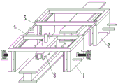
Fig. 1 is a schematic view of the overall structure of a track adjusting device of a bridge crane according to the present invention;
fig. 2 is a schematic view of a positioning mechanism of a track adjusting device of a bridge crane according to the present invention;
fig. 3 is a schematic view of an adjusting mechanism of a track adjusting device of a bridge crane according to the present invention;
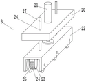
fig. 4 is a schematic view of a moving mechanism of a track adjusting device of a bridge crane according to the present invention.
In the figure: the device comprises a positioning mechanism 1, an adjusting mechanism 2, a moving mechanism 3, an extension rod 4, a sliding hole 5, a positioning frame 6, a positioning plate 7, a threaded rod 8, a hand wheel 9, a positioning nut 10, a first guide hole 11, a first guide rod 12, an adjusting frame 13, a threaded hole 14, a fastening bolt 15, an adjusting plate 16, a first electric telescopic rod 17, a second guide hole 18, a second guide rod 19, a fixing plate 20, a second electric telescopic rod 21, a lifting frame 22, a fixing shell 23, a forward and reverse rotation motor 24, a moving wheel 25, a third guide hole 26 and a third guide rod 27.
Detailed Description
The technical solutions in the embodiments of the present invention will be described clearly and completely with reference to the accompanying drawings in the embodiments of the present invention, and it is obvious that the described embodiments are only some embodiments of the present invention, not all embodiments. Based on the embodiments in the present invention, all other embodiments obtained by a person skilled in the art without creative work belong to the protection scope of the present invention.
Referring to fig. 1 to 4, a bridge crane track adjusting device includes a positioning mechanism 1 and an adjusting mechanism 2, the adjusting mechanism 2 includes an adjusting frame 13, two sides of the adjusting frame 13 are both provided with a first electric telescopic rod 17 via bolts, the first electric telescopic rod 17 has an adjusting plate 16 to move, an output end of the first electric telescopic rod 17 is connected with the adjusting plate 16, the adjusting plate 16 can move to push the bridge crane track to move, so as to improve the efficiency of adjusting the bridge crane track, the two adjusting plates 16 are adopted to improve the convenience of moving the adjusting track, the positioning mechanism 1 includes a positioning frame 6, two sides of the positioning frame 6 are both in threaded connection with a threaded rod 8, the threaded rod 8 rotates on the positioning frame 6, one end of the threaded rod 8 rotates on one side of the positioning plate 7, the threaded rod 8 rotates to drive the positioning plate 7 to move, one end of the threaded rod 8 is provided with the positioning plate 7, can fix a position positioning mechanism 1 on the track that has adjusted under the centre gripping of two locating plates 7, stability when improving guiding mechanism and using, moving mechanism 3 is installed through the bolt in positioning mechanism 1's inside, moving mechanism 3 is including fixed plate 20, two 21 electric telescopic handle are installed through the bolt in the top of fixed plate 20, two 21 electric telescopic handle can drive crane 22 lift, be convenient for positioning mechanism 1 can satisfy different orbital uses, electric telescopic handle two 21's output is connected with crane 22, the set casing 23 is installed through the bolt in crane 22's inside, positive and negative motor 24 is installed through the bolt in the inside of set casing 23, positive and negative motor 24 drives and removes wheel 25 and rotates, it removes on bridge crane's track to be convenient for adjusting device, positive and negative motor 24's output is connected with removes wheel 25.
The back of the positioning frame 6 is welded with an extension rod 4, the extension rod 4 is inserted in the sliding hole 5 in a sliding mode, the distance between the positioning mechanism 1 and the adjusting mechanism 2 can be adjusted, the sliding hole 5 is formed in the front of the adjusting frame 13, and the extension rod 4 is inserted in the sliding hole 5 in a sliding mode; a threaded hole 14 is formed in the top of the adjusting frame 13, a fastening bolt 15 is connected to the inner thread of the threaded hole 14 in a threaded manner, the fastening bolt 15 is arranged inside the threaded hole 14 in a threaded manner, and the fastening bolt 15 can enable the extension rod 4 to be fixed inside the sliding hole 5; the other end of the threaded rod 8 is welded with a hand wheel 9, the outer thread of the threaded rod 8 is connected with a positioning nut 10, and the positioning nut 10 can fix the threaded rod 8 on two sides of the positioning frame 6, so that the stability of the positioning plate 7 in use is improved; one side of the positioning plate 7 is welded with a first guide rod 12, two sides of the positioning frame 6 are respectively provided with a first guide hole 11, the first guide rods 12 are inserted in the first guide holes 11 in a sliding mode, the first guide rods 12 can guide the positioning plate 7, and the stability of the positioning plate 7 during movement is improved; a second guide rod 19 is welded on one side of the adjusting plate 16, two guide holes 18 are formed in the two sides of the adjusting frame 13, the second guide rod 19 is inserted into the second guide holes 18 in a sliding mode, the second guide rod 19 can guide the adjusting plate 16, and stability of the adjusting plate 16 in moving is improved; the top welding of crane 22 has guide bar three 27, and open the top of fixed plate 20 has guide hole three 26, and guide bar three 27 slides and pegs graft in the inside of guide hole three 26, and guide bar three 27 can play the guide effect to crane 22, stability when improving crane 22 and removing.
The utility model discloses a theory of operation does: when the adjusting mechanism is used, when a track is laid, the adjusting device is placed on a fixed track of a bridge crane, the electric telescopic rod II 21 is started, the electric telescopic rod II 21 can drive the lifting frame 22 to lift, when the lifting frame 22 descends, the moving wheel 25 is in contact with the fixed track, the forward and reverse rotating motor 24 is started, the forward and reverse rotating motor 24 drives the moving wheel 25 to rotate, the adjusting device can move on the track of the bridge crane conveniently, the threaded rod 8 is rotated on the positioning frame 6, one end of the threaded rod 8 rotates on one side of the positioning plate 7, the threaded rod 8 rotates to drive the positioning plate 7 to move, the positioning mechanism 1 can be positioned on the fixed track under the clamping of the two positioning plates 7, the adjusting device is fixed, the stability of the adjusting mechanism in use is improved, the electric telescopic rod I17 is started due to the fact that the adjusting mechanism 2 is positioned on the track to be adjusted, the electric telescopic rod I17 is provided with the adjusting plate 16 to move, the adjusting plates 16 move to push the bridge crane track to move, the efficiency of adjusting the bridge crane track is improved, the two adjusting plates 16 are adopted to improve the convenience of moving the adjusting track, the track to be adjusted and the fixed track are on the same straight line, and the track to be adjusted and the fixed track are aligned. The utility model discloses an adjustment mechanism 2 that sets up, 17 electric telescopic handle on the adjustment mechanism 2 take adjustment plate 16 to remove, and the track of laying is waited to promote when adjustment plate 16 removes to remove, will wait to lay the track removal and align with the trapped orbit, adopts two electric telescopic handle about 17 both sides to treat to lay the track and promote the adjustment, improves the efficiency to bridge crane track adjustment.
The above, only be the concrete implementation of the preferred embodiment of the present invention, but the protection scope of the present invention is not limited thereto, and any person skilled in the art is in the technical scope of the present invention, according to the technical solution of the present invention and the utility model, the concept of which is equivalent to replace or change, should be covered within the protection scope of the present invention.
Claims (7)
1. The utility model provides a bridge crane track adjusting device, includes positioning mechanism (1) and guiding mechanism (2), its characterized in that, guiding mechanism (2) is including alignment jig (13), electric telescopic handle (17) is all installed through the bolt in the both sides of alignment jig (13), the output of electric telescopic handle (17) is connected with adjusting plate (16), positioning mechanism (1) is including positioning jig (6), the equal threaded connection in both sides of positioning jig (6) has threaded rod (8), the one end of threaded rod (8) is provided with locating plate (7), moving mechanism (3) is installed through the bolt in positioning mechanism (1), moving mechanism (3) is including fixed plate (20), electric telescopic handle two (21) is installed through the bolt in the top of fixed plate (20), the output of electric telescopic handle two (21) is connected with crane (22), the utility model discloses a crane, including crane, positive and negative rotation motor (24), set casing (23) are installed through the bolt in the inside of crane (22), positive and negative rotation motor (24) are installed through the bolt in the inside of set casing (23), the output of positive and negative rotation motor (24) is connected with removes wheel (25).
2. The rail adjusting device for the bridge crane according to claim 1, wherein the back of the positioning frame (6) is welded with an extension rod (4), the front of the adjusting frame (13) is provided with a sliding hole (5), and the extension rod (4) is slidably inserted into the sliding hole (5).
3. A bridge crane track adjusting device according to claim 1, characterized in that the top of the adjusting frame (13) is provided with a threaded hole (14), and a fastening bolt (15) is connected to the inner thread of the threaded hole (14).
4. A rail adjusting device of a bridge crane according to claim 1, characterized in that a hand wheel (9) is welded at the other end of the threaded rod (8), and a positioning nut (10) is connected to the external thread of the threaded rod (8).
5. The rail adjusting device for the bridge crane according to claim 1, wherein a first guide rod (12) is welded to one side of the positioning plate (7), a first guide hole (11) is formed in each of two sides of the positioning frame (6), and the first guide rod (12) is slidably inserted into the first guide hole (11).
6. The rail adjusting device of the bridge crane according to claim 1, wherein a second guide rod (19) is welded to one side of the adjusting plate (16), two guide holes (18) are formed in both sides of the adjusting frame (13), and the second guide rod (19) is slidably inserted into the second guide hole (18).
7. The rail adjusting device of the bridge crane according to claim 1, wherein a third guide rod (27) is welded on the top of the lifting frame (22), a third guide hole (26) is formed on the top of the fixing plate (20), and the third guide rod (27) is slidably inserted into the third guide hole (26).
Priority Applications (1)
| Application Number | Priority Date | Filing Date | Title |
|---|---|---|---|
| CN202122665671.8U CN215048090U (en) | 2021-11-03 | 2021-11-03 | Track adjusting device of bridge crane |
Applications Claiming Priority (1)
| Application Number | Priority Date | Filing Date | Title |
|---|---|---|---|
| CN202122665671.8U CN215048090U (en) | 2021-11-03 | 2021-11-03 | Track adjusting device of bridge crane |
Publications (1)
| Publication Number | Publication Date |
|---|---|
| CN215048090U true CN215048090U (en) | 2021-12-07 |
Family
ID=79218694
Family Applications (1)
| Application Number | Title | Priority Date | Filing Date |
|---|---|---|---|
| CN202122665671.8U Active CN215048090U (en) | 2021-11-03 | 2021-11-03 | Track adjusting device of bridge crane |
Country Status (1)
| Country | Link |
|---|---|
| CN (1) | CN215048090U (en) |
-
2021
- 2021-11-03 CN CN202122665671.8U patent/CN215048090U/en active Active
Similar Documents
| Publication | Publication Date | Title |
|---|---|---|
| CN215048090U (en) | Track adjusting device of bridge crane | |
| CN214007103U (en) | Overhauling device for well control pressure test safety protection equipment | |
| CN209554644U (en) | Boom hoisting is used in a kind for the treatment of of domestic animal | |
| CN216097176U (en) | Welding device for steel structure | |
| CN213923894U (en) | Lifting device for control engineering is convenient for fix different objects | |
| CN211688148U (en) | Hoisting accessory is used in motor maintenance | |
| CN215115300U (en) | Underground water sampling device | |
| CN213422139U (en) | Steel bar diameter detection device for building engineering detection | |
| CN211946115U (en) | Flexible floating FRP pipe hoisting accessory | |
| CN211004277U (en) | A rail mounted lifting device for construction of high-rise building curtain | |
| CN219751821U (en) | Goods fixing device | |
| CN220882029U (en) | Positioning fixture is used in part processing of convenient dismantlement | |
| CN213783221U (en) | Solar energy frame driving anchor clamps | |
| CN217253009U (en) | Worm gear box drilling clamp | |
| CN218946758U (en) | Hoop multi-point welding device | |
| CN216632786U (en) | High-stability steel pipe cutting equipment | |
| CN216584007U (en) | Four-column type lifter | |
| CN210817579U (en) | Fixing device for mechanical drilling | |
| CN216971223U (en) | Automatic tube penetrating machine for tube type heat exchanger | |
| CN214923468U (en) | Centerless grinding machine tool workpiece fixing device | |
| CN220093594U (en) | Power battery end cover plate welding and fixing device | |
| CN217708503U (en) | Portable large module positioning and boxing assembly manipulator | |
| CN213497365U (en) | Steel construction multi-angle adjustable welding mechanism | |
| CN220498228U (en) | Frock clamp is used in auto-parts welding | |
| CN220161875U (en) | Movable arm fixing device |
Legal Events
| Date | Code | Title | Description |
|---|---|---|---|
| GR01 | Patent grant | ||
| GR01 | Patent grant |