CN215046155U - Feeding mechanism for spherical tray forming die - Google Patents
Feeding mechanism for spherical tray forming die Download PDFInfo
- Publication number
- CN215046155U CN215046155U CN202120091179.1U CN202120091179U CN215046155U CN 215046155 U CN215046155 U CN 215046155U CN 202120091179 U CN202120091179 U CN 202120091179U CN 215046155 U CN215046155 U CN 215046155U
- Authority
- CN
- China
- Prior art keywords
- support
- oil
- controller
- driven
- driving
- Prior art date
- Legal status (The legal status is an assumption and is not a legal conclusion. Google has not performed a legal analysis and makes no representation as to the accuracy of the status listed.)
- Active
Links
Images


Landscapes
- Moulds For Moulding Plastics Or The Like (AREA)
Abstract
The utility model relates to the technical field of mechanical equipment, in particular to a feeding mechanism for a spherical tray forming die, which can automatically convey a formed spherical tray by arranging the feeding mechanism, thereby improving the automation degree, saving a large amount of labor and time, improving the working efficiency and improving the practicability; the automatic transmission device comprises a driving support, a motor, a reduction gearbox, a driving rotating shaft, a driving rotating roller, a driven support, a driven rotating shaft, a driven rotating roller, a conveying belt, a bottom plate, an oil tank, an oil cylinder rod, a constraint support, a connecting shaft, a connecting seat, a slide, a controller supporting rod, a controller, a baffle connecting frame and a baffle, wherein the motor is installed on the top end of the reduction gearbox, the output end of the motor is connected with the input end of the reduction gearbox, the output end of the reduction gearbox penetrates through the front end of the driving support to be connected with the front end of the driving rotating shaft, the driving rotating roller is installed on the driving rotating shaft, and the baffle is installed on the top ends of the driving support and the driven support through the baffle connecting frame.
Description
Technical Field
The utility model relates to a mechanical equipment's technical field especially relates to a spherical tray feeding mechanism for forming die.
Background
As is known, a spherical pallet is a medium that transforms static goods into dynamic goods, a cargo platform, but also a movable platform. The spherical tray is formed by injection molding on a spherical tray forming die, the spherical tray which is completed by injection molding needs to be transported to the next procedure, the existing transportation method is manual transportation, a large amount of labor and time are consumed, the working efficiency is low, and the practicability is poor.
SUMMERY OF THE UTILITY MODEL
In order to solve the technical problem, the utility model provides a can carry out the automatic transport to the spherical tray after the shaping, improve degree of automation, also saved a large amount of manual works and time, improve its work efficiency, also improve the feeding mechanism for spherical tray forming die of its practicality.
The utility model relates to a feeding mechanism for a spherical tray forming die, which comprises a driving support, a motor, a reduction gearbox, a driving rotating shaft, a driving rotating roller, a driven support, a driven rotating shaft, a driven rotating roller, a conveyor belt, a bottom plate, an oil tank, an oil cylinder rod, a restraint support, a connecting shaft, a connecting seat, a slide, a controller support rod, a controller, a baffle connecting frame and a baffle, wherein the motor is arranged at the top end of the reduction gearbox, the output end of the motor is connected with the input end of the reduction gearbox, the reduction gearbox is arranged at the front end of the driving support, the driving rotating shaft is rotatably arranged on the driving support, the output end of the reduction gearbox passes through the front end of the driving support and is connected with the front end of the driving rotating shaft, the driving rotating roller is arranged on the driving rotating shaft, the driven rotating shaft is rotatably arranged on the driven rotating shaft, the driven rotating roller and the driving rotating roller are synchronously driven through the conveyor belt, the bottom plate is arranged at the lower part of the rear end of the driven support, the oil tank is installed on the bottom plate top, the inside oil storage chamber that is provided with of oil tank, be provided with machine oil in the oil storage chamber, the hydro-cylinder is installed on the oil tank top, the oil tank supplies the hydro-cylinder fuel feeding, hydro-cylinder pole bottom is connected with the hydro-cylinder output, restraint support mounting is on the bottom plate top, restraint support top passes through connecting axle rotatable coupling with the slide bottom, connecting seat rotatable coupling is passed through with the slide bottom in hydro-cylinder pole top, controller branch is installed on the bottom plate top, the controller is installed on controller branch, the controller is connected with motor and hydro-cylinder electricity, the baffle passes through the baffle link and installs on initiative support and driven support top.
The utility model discloses a spherical tray feeding mechanism for forming die still includes the alarm lamp, and the alarm lamp is installed at the controller right-hand member, and the alarm lamp is connected with the controller electricity.
The utility model discloses a feeding mechanism for spherical tray forming die still includes emergency stop button, and emergency stop button installs in the controller rear end, and emergency stop button is connected with the controller electricity.
The utility model discloses a feeding mechanism for spherical tray forming die, oil tank left end rear portion is provided with the liquid level observation window.
The utility model discloses a feeding mechanism for spherical tray forming die still includes into oil cap, and oil tank top intercommunication is provided with the oil inlet, advances oil cap lid dress and locates at the oil inlet.
The utility model discloses a spherical tray feeding mechanism for forming die still includes the crashproof pad, and the crashproof pad is installed in the baffle rear end.
The utility model discloses a spherical tray feeding mechanism for forming die, initiative support, driven support and bottom plate are all fixed subaerial through the bolt.
Compared with the prior art, the beneficial effects of the utility model are that: open the hydro-cylinder through the controller, make the interior machine oil of oil tank supply with the hydro-cylinder, then the hydro-cylinder pole passes through the connecting seat and drives the slide motion, after slide and last one process butt joint, close the hydro-cylinder, then injection moulding's spherical tray is then leading-in to the conveyer belt on through the slide, open the motor through the controller simultaneously, make the reducing gear box open the initiative pivot and rotate, the epaxial initiative of initiative commentaries on classics roller then drives the conveyer belt transmission, the conveyer belt is then carried to spherical tray above that to next one process in, through setting up this equipment, can carry out the automatic transport to the spherical tray after the shaping, the degree of automation is improved, a large amount of manual work and time have also been saved, improve its work efficiency, the practicality has also been improved.
Drawings
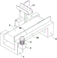
FIG. 1 is an isometric view of the present invention;
FIG. 2 is a schematic left side view of the structure of FIG. 1;
FIG. 3 is a front cross-sectional structural view of FIG. 1;
in the drawings, the reference numbers: 1. an active support; 2. a motor; 3. a reduction gearbox; 4. a driving rotating shaft; 5. actively rotating the roller; 6. a driven bracket; 7. a driven rotating shaft; 8. a driven roller; 9. a conveyor belt; 10. a base plate; 11. an oil tank; 12. an oil cylinder; 13. a cylinder rod; 14. a restraint bracket; 15. a connecting shaft; 16. a connecting seat; 17. a slide; 18. a controller strut; 19. a controller; 20. an alarm lamp; 21. an emergency stop button; 22. a liquid level observation window; 23. an oil inlet cover; 24. an anti-collision pad; 25. a baffle plate connecting frame; 26. and a baffle plate.
Detailed Description
The following detailed description of the embodiments of the present invention is provided with reference to the accompanying drawings and examples. The following examples are intended to illustrate the invention, but are not intended to limit the scope of the invention.
As shown in fig. 1 to 3, the feeding mechanism for a spherical tray forming mold of the present invention comprises a driving support 1, a motor 2, a reduction box 3, a driving rotating shaft 4, a driving rotating roller 5, a driven support 6, a driven rotating shaft 7, a driven rotating roller 8, a conveyor belt 9, a bottom plate 10, an oil tank 11, an oil cylinder 12, an oil cylinder rod 13, a restraining support 14, a connecting shaft 15, a connecting seat 16, a slide 17, a controller support rod 18, a controller 19, a baffle connecting frame 25 and a baffle 26, wherein the motor 2 is installed at the top end of the reduction box 3, the output end of the motor 2 is connected with the input end of the reduction box 3, the reduction box 3 is installed at the front end of the driving support 1, the driving rotating shaft 4 is rotatably installed on the driving support 1, the output end of the reduction box 3 passes through the front end of the driving support 1 to be connected with the front end of the driving rotating shaft 4, the driving rotating roller 5 is installed on the driving rotating shaft 4, the driven rotating shaft 7 is rotatably installed on the driven support 6, the driven rotating roller 8 is installed on a driven rotating shaft 7, the driven rotating roller 8 and the driving rotating roller 5 are in synchronous transmission through a conveying belt 9, the bottom plate 10 is installed at the lower portion of the rear end of the driven support 6, the oil tank 11 is installed at the top end of the bottom plate 10, an oil storage cavity is formed in the oil tank 11, engine oil is arranged in the oil storage cavity, the oil tank 12 supplies oil to the oil tank 12, the bottom end of an oil cylinder rod 13 is connected with the output end of the oil cylinder 12, the restraint support 14 is installed at the top end of the bottom plate 10, the top end of the restraint support 14 is rotatably connected with the bottom end of the slide 17 through a connecting shaft 15, the top end of the oil cylinder rod 13 is rotatably connected with the bottom end of the slide 17 through a connecting seat 16, the controller support rod 18 is installed at the top end of the bottom plate 10, the controller 19 is installed on the controller support rod 18, the controller 19 is electrically connected with the motor 2 and the oil cylinder 12, and the baffle 26 is installed at the top ends of the driving support 1 and the driven support 6 through a baffle connecting frame 25; open hydro-cylinder 12 through controller 19, make the interior machine oil of oil tank 11 supply with hydro-cylinder 12, then hydro-cylinder pole 13 drives slide 17 motion through connecting seat 16, after slide 17 docks with last process, close hydro-cylinder 12, then injection moulding's spherical tray is then leading-in to conveyer belt 9 through slide 17 on, open motor 2 through controller 19 simultaneously, make reducing gear box 3 open initiative pivot 4 and rotate, initiative on the initiative pivot 4 is changeed roller 5 and is then driven conveyer belt 9 transmission, conveyer belt 9 is then carried to the spherical tray above that to next process in, through setting up this equipment, can carry out the automatic conveyor to the spherical tray after the shaping, improve degree of automation, also save a large amount of manual work and time, improve its work efficiency, also improved its practicality.
The utility model discloses a feeding mechanism for a spherical tray forming die, which also comprises an alarm lamp 20, wherein the alarm lamp 20 is arranged at the right end of a controller 19, and the alarm lamp 20 is electrically connected with the controller 19; through setting up alarm lamp 20, when equipment breaks down, the staff of being convenient for in time discovers.
The utility model discloses a feeding mechanism for spherical tray forming die, which also comprises an emergency stop button 21, wherein the emergency stop button 21 is arranged at the rear end of the controller 19, and the emergency stop button 21 is electrically connected with the controller 19; by providing the emergency stop button 21, the apparatus can be stopped by pressing the emergency stop button 21 when an emergency situation occurs.
The utility model relates to a feeding mechanism for a spherical tray forming die, a liquid level observation window 22 is arranged at the rear part of the left end of an oil tank 11; the liquid level observation window 22 is arranged, so that the capacity of the engine oil in the oil storage cavity can be known conveniently.
The utility model discloses a feeding mechanism for a spherical tray forming die, which also comprises an oil inlet cover 23, wherein the top end of an oil tank 11 is communicated with and provided with an oil inlet, and the oil inlet cover 23 is covered at the oil inlet; by arranging the oil inlet cover 23, the dust can be prevented from polluting engine oil in the oil storage cavity through the oil inlet.
The utility model discloses a feeding mechanism for a spherical tray forming die, which also comprises an anti-collision pad 24, wherein the anti-collision pad 24 is arranged at the rear end of a baffle 26; through setting up crashproof pad 24, can play the effect of crashproof to the spherical tray after the shaping.
In the feeding mechanism for the spherical tray forming die, the driving support 1, the driven support 6 and the bottom plate 10 are all fixed on the ground through bolts; the overall stability of the device can be improved.
The utility model discloses a feeding mechanism for spherical tray forming die, it is at the during operation, at first open hydro-cylinder 12 through controller 19, make the interior machine oil supply hydro-cylinder 12 of oil tank 11, then hydro-cylinder pole 13 drives slide 17 motion through connecting seat 16, after slide 17 docks with last one process, close hydro-cylinder 12, then injection moulding's spherical tray is then through slide 17 leading-in to conveyer belt 9 on, open motor 2 through controller 19 simultaneously, make reducing gear box 3 open 4 rotations of initiative pivot, the epaxial initiative change roller 5 of initiative pivot 4 then drives the transmission of conveyer belt 9, conveyer belt 9 then to the spherical tray on it carry to down in the one process can.
The feeding mechanism for the spherical tray forming die has the advantages that the installation mode, the connection mode or the setting mode are common mechanical modes, and the feeding mechanism can be implemented as long as the beneficial effects can be achieved; the utility model discloses a spherical tray is feeding mechanism's for forming die motor 2, hydro-cylinder 12, controller 19, alarm lamp 20 and scram button 21 for purchase on the market, this industry technical staff only need according to its subsidiary instructions install and operate can.
The foregoing is only a preferred embodiment of the present invention, and it should be noted that, for those skilled in the art, a plurality of modifications and variations can be made without departing from the technical principle of the present invention, and these modifications and variations should also be regarded as the protection scope of the present invention.
Claims (7)
1. A feeding mechanism for a spherical tray forming die is characterized by comprising a driving support (1), a motor (2), a reduction gearbox (3), a driving rotating shaft (4), a driving rotating roller (5), a driven support (6), a driven rotating shaft (7), a driven rotating roller (8), a conveyor belt (9), a bottom plate (10), an oil tank (11), an oil cylinder (12), an oil cylinder rod (13), a constraint support (14), a connecting shaft (15), a connecting seat (16), a slide (17), a controller support rod (18), a controller (19), a baffle connecting frame (25) and a baffle (26), wherein the motor (2) is arranged at the top end of the reduction gearbox (3), the output end of the motor (2) is connected with the input end of the reduction gearbox (3), the reduction gearbox (3) is arranged at the front end of the driving support (1), the driving rotating shaft (4) is rotatably arranged on the driving support (1), the output end of the reduction gearbox (3) penetrates through the front end of the driving support (1) to be connected with the front end of the driving rotating shaft (4), the driving rotating roller (5) is installed on the driving rotating shaft (4), the driven rotating shaft (7) is rotatably installed on the driven support (6), the driven rotating roller (8) is installed on the driven rotating shaft (7), the driven rotating roller (8) and the driving rotating roller (5) are synchronously driven through a conveyor belt (9), the bottom plate (10) is installed at the lower part of the rear end of the driven support (6), the oil tank (11) is installed at the top end of the bottom plate (10), an oil storage cavity is arranged inside the oil tank (11), engine oil is arranged in the oil storage cavity, the oil tank (12) is installed at the top end of the oil tank (11), the oil tank (11) supplies oil to the oil cylinder (12), the bottom end of the oil cylinder rod (13) is connected with the output end of the oil cylinder (12), the restraint support (14) is installed at the top end of the bottom plate (10), the top end of the restraint support (14) is rotatably connected with the bottom end of the slide (17) through a connecting shaft (15), the top end of an oil cylinder rod (13) is rotatably connected with the bottom end of a slide (17) through a connecting seat (16), a controller supporting rod (18) is installed at the top end of a bottom plate (10), a controller (19) is installed on the controller supporting rod (18), the controller (19) is electrically connected with a motor (2) and an oil cylinder (12), and a baffle plate (26) is installed at the top ends of a driving support (1) and a driven support (6) through a baffle plate connecting frame (25).
2. The feeding mechanism for the spherical tray forming die according to claim 1, further comprising a warning lamp (20), wherein the warning lamp (20) is installed at the right end of the controller (19), and the warning lamp (20) is electrically connected with the controller (19).
3. The feeding mechanism for the spherical tray forming die as claimed in claim 2, further comprising an emergency stop button (21), wherein the emergency stop button (21) is mounted at the rear end of the controller (19), and the emergency stop button (21) is electrically connected with the controller (19).
4. The feeding mechanism for the spherical tray forming die as claimed in claim 3, wherein the rear part of the left end of the oil tank (11) is provided with a liquid level observation window (22).
5. The feeding mechanism for the spherical tray forming die according to claim 4, further comprising an oil inlet cover (23), wherein an oil inlet is formed at the top end of the oil tank (11) in a communicating manner, and the oil inlet cover (23) is covered at the oil inlet.
6. The feeding mechanism for the spherical tray forming die as claimed in claim 5, further comprising a crash pad (24), wherein the crash pad (24) is mounted at the rear end of the baffle (26).
7. The feeding mechanism for the spherical tray forming die as claimed in claim 6, wherein the driving bracket (1), the driven bracket (6) and the bottom plate (10) are all fixed on the ground by bolts.
Priority Applications (1)
| Application Number | Priority Date | Filing Date | Title |
|---|---|---|---|
| CN202120091179.1U CN215046155U (en) | 2021-01-14 | 2021-01-14 | Feeding mechanism for spherical tray forming die |
Applications Claiming Priority (1)
| Application Number | Priority Date | Filing Date | Title |
|---|---|---|---|
| CN202120091179.1U CN215046155U (en) | 2021-01-14 | 2021-01-14 | Feeding mechanism for spherical tray forming die |
Publications (1)
| Publication Number | Publication Date |
|---|---|
| CN215046155U true CN215046155U (en) | 2021-12-07 |
Family
ID=79250441
Family Applications (1)
| Application Number | Title | Priority Date | Filing Date |
|---|---|---|---|
| CN202120091179.1U Active CN215046155U (en) | 2021-01-14 | 2021-01-14 | Feeding mechanism for spherical tray forming die |
Country Status (1)
| Country | Link |
|---|---|
| CN (1) | CN215046155U (en) |
Cited By (1)
| Publication number | Priority date | Publication date | Assignee | Title |
|---|---|---|---|---|
| CN114538033A (en) * | 2022-04-21 | 2022-05-27 | 河北科技大学 | Be applied to integrated dispensing device's syringe loading attachment |
-
2021
- 2021-01-14 CN CN202120091179.1U patent/CN215046155U/en active Active
Cited By (1)
| Publication number | Priority date | Publication date | Assignee | Title |
|---|---|---|---|---|
| CN114538033A (en) * | 2022-04-21 | 2022-05-27 | 河北科技大学 | Be applied to integrated dispensing device's syringe loading attachment |
Similar Documents
| Publication | Publication Date | Title |
|---|---|---|
| CN201132690Y (en) | Double-layer expansion conveyor | |
| CN215046155U (en) | Feeding mechanism for spherical tray forming die | |
| CN211338032U (en) | Novel automatic loading system | |
| CN212149489U (en) | Intelligent electronic equipment's packing carton accessory automatic assembly mechanism | |
| CN212386381U (en) | Fur duck car with conveyer | |
| CN111731787B (en) | Automobile assembling equipment | |
| CN215098546U (en) | Tea wax packagine machine | |
| CN113044535A (en) | Oil cooler assembly partial shipment tray line | |
| CN213533548U (en) | Automatic feeding device of injection molding machine | |
| CN221497796U (en) | Hopper lifting structure of transport vehicle | |
| CN218296623U (en) | Material conveying mechanism for automobile part production | |
| CN216611847U (en) | Automatic box filling machine | |
| CN212374290U (en) | Variable-azimuth conveyor for warehouse management | |
| CN221369166U (en) | Automatic caching platform | |
| CN214358437U (en) | Plastic part guiding mechanism | |
| CN216425740U (en) | Belt formula jacking equipment for article are carried and fall | |
| CN219097984U (en) | Programmable AGV device of plugging into based on PLC and wireless network bridge | |
| CN219884214U (en) | Logistics packing machine for fragile products | |
| CN215325763U (en) | Commodity circulation is with handling device convenient to change height | |
| CN221795878U (en) | Conveying device for roll paper packaging box production | |
| CN214651506U (en) | Pure aluminium's rectangle container conveyor of unloading | |
| CN210635703U (en) | Sub-packaging device of graphene power improver for automobile | |
| CN221564963U (en) | Screw reclaimer for stock bin | |
| CN220884195U (en) | Intelligent transfer machine | |
| CN208263299U (en) | A kind of mold automatic blanking device that stability is high |
Legal Events
| Date | Code | Title | Description |
|---|---|---|---|
| GR01 | Patent grant | ||
| GR01 | Patent grant |