CN215040285U - Automobile B-pillar edge covering clamping fixture - Google Patents
Automobile B-pillar edge covering clamping fixture Download PDFInfo
- Publication number
- CN215040285U CN215040285U CN202122637890.5U CN202122637890U CN215040285U CN 215040285 U CN215040285 U CN 215040285U CN 202122637890 U CN202122637890 U CN 202122637890U CN 215040285 U CN215040285 U CN 215040285U
- Authority
- CN
- China
- Prior art keywords
- block
- install
- mould
- bottom plate
- cylinder
- Prior art date
- Legal status (The legal status is an assumption and is not a legal conclusion. Google has not performed a legal analysis and makes no representation as to the accuracy of the status listed.)
- Active
Links
Images

Landscapes
- Shaping Metal By Deep-Drawing, Or The Like (AREA)
Abstract
The utility model discloses a car B post mould of borduring, include: the device comprises a mould base plate, a profiling block, a fixed block, a rotary cylinder, a sliding table cylinder, a profiling pressing block, a stop block and a plurality of air blowing copper pipes, wherein the profiling block, the fixed block, the rotary cylinder and the sliding table cylinder are arranged on the mould base plate; the utility model discloses can realize accurate stable positioning to the product, guarantee that product processingquality is stable, reduce workman intensity of labour, improve production efficiency.
Description
Technical Field
The utility model relates to an automotive interior spare automated processing field especially relates to a car B post mould of borduring.
Background
With the continuous improvement of the quality of life, automobiles are more and more widely used, and the quality requirements of people on automobile interior parts are higher and higher. In the manufacturing and processing procedure of the automotive interior part, the edge covering is an indispensable ring, and in the edge covering process, an important production step is to turn over the cloth edge outside the injection-molded framework and attach the cloth edge to the inner side of the framework, and then weld the turned cloth on the framework by using an ultrasonic welding head. The traditional flanging welding process is generally realized by adopting a manual operation method, but the manual operation method has the defects of labor waste, large product quality error, unstable product quality and the like.
SUMMERY OF THE UTILITY MODEL
In order to solve the defects of the prior art, the utility model aims to provide a car B post mould of borduring.
In order to achieve the above purpose, the utility model is realized by the following technical scheme:
an automobile B-pillar edge covering clamping fixture comprises: the mould bottom plate, install in profile modeling piece, fixed block, revolving cylinder and slip table cylinder on the mould bottom plate, install in the profile modeling briquetting of revolving cylinder front end, install in the piece that blocks of slip table cylinder front end, and install in a plurality of copper pipe of blowing on profile modeling piece and the piece that blocks, still install the gas circuit on the mould bottom plate and insert soon.
The fixed block is installed on pneumatic single finger presss from both sides, pneumatic single finger presss from both sides through the support mounting on the mould bottom plate, perhaps install in on the slip table cylinder.
Compared with the prior art, the beneficial effects of the utility model are that: the edge covering mould can realize accurate and stable positioning on products, ensures stable product processing quality, reduces labor intensity of workers and improves production efficiency.
Drawings
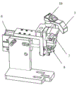
Fig. 1 is a schematic structural view of the present invention;
fig. 2 is a schematic view of a partial structure of the present invention.
In the figure: 1-a mould base plate; 2-a shaped block; 3, fixing blocks; 4-a rotating cylinder; 5-profiling briquetting; 6-a slipway cylinder; 7-a barrier; 8-air blowing copper pipe; 9-gas path quick insertion; 10-pneumatic single finger gripper.
Detailed Description
In order to make the objects, technical solutions and advantages of the present invention clearer and more obvious, the present invention is further described in detail below with reference to the accompanying drawings and embodiments.
As shown in fig. 1 to fig. 2, the utility model provides a car B post mould of borduring, include: the mould bottom plate 1, install in profile modeling block 2, fixed block 3, revolving cylinder 4 and slip table cylinder 6 on the mould bottom plate, install in the profile modeling briquetting 5 of revolving cylinder 4 front end, install in the piece 7 that blocks of slip table cylinder 6 front end, and install in a plurality of copper pipe 8 of blowing on profile modeling block 2 and the piece 7 that blocks, still install the gas circuit on the mould bottom plate 1 and insert 9 soon.
The fixed block 3 is arranged on a pneumatic single-finger clamp 10, and the pneumatic single-finger clamp 10 is arranged on the mould bottom plate 1 through a support or arranged on the sliding table cylinder 6.
The utility model discloses a concrete working process does:
manually or mechanically placing the B-column product on a mould, pre-positioning the B-column product through the profiling block 2, starting the equipment, rotating the air cylinder 4 to act, and driving the profiling block 5 to compress the B-column product so as to enable the B-column product to be attached to the mould; then the sliding table cylinder 6 acts to drive the blocking block 7 to move forwards to position the B column product; the pneumatic single-finger clamp 10 acts to drive the fixing block 3 to attach the inner warped part of the B-column product to the mould; then the air blowing copper pipe 8 is ventilated to blow the B-column product cloth to form a certain angle with the clamping fixture, so that the power source robot can drive the welding structure to weld the edge.
The above description is only exemplary of the present invention and should not be taken as limiting the scope of the present invention, as any modifications, equivalents, improvements and the like made within the spirit and principles of the present invention are intended to be included within the scope of the present invention.
Claims (2)
1. The utility model provides a car B post mould of borduring which characterized in that includes: mould bottom plate (1), install in profile modeling piece (2), fixed block (3), revolving cylinder (4) and slip table cylinder (6) on the mould bottom plate, install in profile modeling briquetting (5) of revolving cylinder (4) front end, install in block piece (7) of slip table cylinder (6) front end, and install in a plurality of copper pipe (8) of blowing on profile modeling piece (2) and block piece (7), still install the gas circuit on mould bottom plate (1) and insert (9) soon.
2. The automobile B-pillar binding clamping fixture according to claim 1, wherein the fixing block (3) is mounted on a pneumatic single-finger clamp (10), and the pneumatic single-finger clamp (10) is mounted on a clamping fixture bottom plate (1) through a support or mounted on the sliding table cylinder (6).
Priority Applications (1)
| Application Number | Priority Date | Filing Date | Title |
|---|---|---|---|
| CN202122637890.5U CN215040285U (en) | 2021-11-01 | 2021-11-01 | Automobile B-pillar edge covering clamping fixture |
Applications Claiming Priority (1)
| Application Number | Priority Date | Filing Date | Title |
|---|---|---|---|
| CN202122637890.5U CN215040285U (en) | 2021-11-01 | 2021-11-01 | Automobile B-pillar edge covering clamping fixture |
Publications (1)
| Publication Number | Publication Date |
|---|---|
| CN215040285U true CN215040285U (en) | 2021-12-07 |
Family
ID=79218304
Family Applications (1)
| Application Number | Title | Priority Date | Filing Date |
|---|---|---|---|
| CN202122637890.5U Active CN215040285U (en) | 2021-11-01 | 2021-11-01 | Automobile B-pillar edge covering clamping fixture |
Country Status (1)
| Country | Link |
|---|---|
| CN (1) | CN215040285U (en) |
-
2021
- 2021-11-01 CN CN202122637890.5U patent/CN215040285U/en active Active
Similar Documents
| Publication | Publication Date | Title |
|---|---|---|
| CN204934987U (en) | A kind of automobile roof assembly welding clamp | |
| CN206277069U (en) | Detent mechanism for positioning automobile metal plate work | |
| CN215040285U (en) | Automobile B-pillar edge covering clamping fixture | |
| CN210818183U (en) | Flexible frock of bicycle frame automatic weld | |
| CN209407890U (en) | A kind of nonstandard special plane that flange and spot-welding technology are integrated in one | |
| CN107498292B (en) | Positioning and assembling device for outer water cutting end cover of front door of automobile | |
| CN206277088U (en) | The automobile metal plate work air-cylinder type positioner of upset can be realized | |
| CN105904475A (en) | Workpiece positioning gripper of intelligent robot rolling and edge covering system | |
| CN214770042U (en) | Welding device for sheet metal parts | |
| CN211414175U (en) | Automatic welding workbench for metal oil filling pipe of automobile | |
| CN103949880A (en) | Automatic vehicle cover assembling robot and working method thereof | |
| CN203804546U (en) | Robot for assembling vehicle cover automatically | |
| CN205044849U (en) | Back lid and ventilator assembly fixture of car car light | |
| CN216578658U (en) | Pneumatic clamp for clamping and positioning large-size plate glass product | |
| CN210966596U (en) | Punching mechanism for air pipe flange production line | |
| CN212602309U (en) | Suitcase carpet production is with die-cut mould convenient to clearance waste material | |
| CN214641341U (en) | Welding positioning mould of robot | |
| CN219238535U (en) | Switch bracket shaping and clamping mechanism | |
| CN112775612B (en) | Welding positioning tool and welding system | |
| CN112296510B (en) | Positioning welding clamp for outer plate of back door | |
| CN218775526U (en) | Tee bend card presses all-in-one | |
| CN214236869U (en) | Novel welding fixture | |
| CN204818524U (en) | Weld positioning fixture in advance | |
| CN216541540U (en) | Double-gun six-shaft automatic welding equipment | |
| CN210788949U (en) | Flanging tool in 3C electronic field |
Legal Events
| Date | Code | Title | Description |
|---|---|---|---|
| GR01 | Patent grant | ||
| GR01 | Patent grant |