CN214976899U - Omnibearing pipe laying mechanism - Google Patents
Omnibearing pipe laying mechanism Download PDFInfo
- Publication number
- CN214976899U CN214976899U CN202121239591.XU CN202121239591U CN214976899U CN 214976899 U CN214976899 U CN 214976899U CN 202121239591 U CN202121239591 U CN 202121239591U CN 214976899 U CN214976899 U CN 214976899U
- Authority
- CN
- China
- Prior art keywords
- laying
- pipe
- wheel
- guide rail
- drive
- Prior art date
- Legal status (The legal status is an assumption and is not a legal conclusion. Google has not performed a legal analysis and makes no representation as to the accuracy of the status listed.)
- Active
Links
Images


Abstract
The utility model relates to an all-round pipe laying mechanism, including transverse guide, the longitudinal rail of setting on transverse guide, drive longitudinal rail along transverse rail removal's transverse driving piece, set up the pipe laying subassembly and the drive pipe laying subassembly on longitudinal rail along longitudinal rail removal's longitudinal driving piece. This all-round pipe laying mechanism can buckle tubular product and lay in the recess of panel automatically, can change the direction of laying wantonly according to the actual structure of recess to adapt to the panel of different models or size, when laying on one side, can also make tubular product and panel relatively fixed, avoid tubular product to deviate from in the recess of panel, thereby guaranteed product quality.
Description
Technical Field
The utility model relates to a radiation plate processing technology field especially relates to an all-round pipe laying mechanism for radiation system.
Background
The radiation plate has become popular due to its features of energy saving, comfort, no occupation of room area, etc. The radiation plate needs to use a U-shaped or S-shaped radiation pipe. In the prior art, a common pipe is generally bent by a pipe bending device, and then the bent pipe after being formed is assembled into an aluminum substrate. The processing efficiency is poor, if the bent pipe is not in place, the bent pipe is difficult to be arranged in the aluminum substrate, so that products are scrapped, and the processing cost is increased.
SUMMERY OF THE UTILITY MODEL
The utility model aims at providing a can be automatically at all-round piping mechanism of panel surface piping.
The utility model discloses a realize through following technical scheme: an omnibearing pipe laying mechanism comprises a transverse guide rail, a longitudinal guide rail arranged on the transverse guide rail, a transverse driving piece for driving the longitudinal guide rail to move along the transverse guide rail, a pipe laying assembly arranged on the longitudinal guide rail and a longitudinal driving piece for driving the pipe laying assembly to move along the longitudinal guide rail, wherein the pipe laying assembly comprises a moving seat, a pipe guiding module, a lifting seat, a lifting guiding rail, a lifting seat driving piece, a turntable driving piece and a pipe laying module, the moving seat is arranged on the longitudinal guide rail, the pipe guiding module is arranged on the moving seat, the pipe guiding module comprises a positioning wheel, a clamping wheel, a positioning wheel driving piece and a clamping wheel driving piece, the positioning wheel driving piece can drive the positioning wheel to rotate, the clamping wheel is correspondingly arranged on one side of the positioning wheel, a clamping guiding channel is formed between the clamping wheel and the positioning wheel, and the clamping wheel driving piece can drive the clamping wheel to move so as to clamp or loosen a pipe in the clamping guiding channel, the pipe laying module comprises a mounting plate, a laying positioning wheel, a laying pressing wheel and a pressing wheel driving part, wherein the laying positioning wheel, the laying pressing wheel and the laying positioning wheel are arranged on the mounting plate correspondingly, a positioning channel is formed between the laying pressing wheel and the laying positioning wheel, and the pressing wheel driving part can drive the laying pressing wheel to move so as to clamp or loosen a pipe fitting in the positioning channel.
In order to guide the pipe fitting, the top end of the pipe fitting guide module is provided with a pipe inlet, and the bottom end of the pipe fitting guide module is provided with a pipe fitting channel.
In order to facilitate driving the tube laying module to move transversely, a first rack is arranged on the transverse guide rail, a first rotating shaft is arranged on one side of the longitudinal guide rail, first gears are arranged at two ends of the first rotating shaft and meshed with the first rack, the transverse driving piece is connected with the first rotating shaft, and the transverse driving piece can drive the first rotating shaft to rotate so as to drive the longitudinal guide rail to move transversely along the transverse guide rail.
In order to facilitate the driving of the pipe laying module to longitudinally move, a second rack is arranged on the longitudinal guide rail, a second rotating shaft is arranged on one side of the moving seat, second gears are arranged at two ends of the second rotating shaft and meshed with the second rack, the longitudinal driving piece is connected with the second rotating shaft, and the longitudinal driving piece can drive the second rotating shaft to rotate so as to drive the moving seat to longitudinally move along the longitudinal guide rail.
In order to facilitate the lifting of the driving lifting seat, a lifting guide rail is arranged on the lifting seat and slides along a lifting guide rail, a third rack is arranged on the lifting guide rail, a third rotating shaft is arranged on the moving seat, a third gear is arranged on the third rotating shaft and meshed with the third rack, a driving piece of the lifting seat is connected with the third rotating shaft, and the driving piece of the lifting seat can drive the third rotating shaft to rotate so as to drive the lifting seat to lift along the lifting guide rail.
In order to facilitate the rotation of the driving turntable, a fluted disc is arranged on the turntable, and the turntable driving piece drives the fluted disc to rotate through a fourth rotating shaft.
In order to avoid the compression and deformation of the plate by the compress pressing wheel and the compress positioning wheel, a spring is arranged between the mounting plate and the turntable, and the mounting plate is elastically connected with the turntable through the spring.
Because tubular product lay and not fixed in panel, if deviate from in the recess of follow panel very easily in taking place vibrations, consequently, the utility model discloses still be equipped with on the mounting panel and be used for the subassembly of dotting of pipe fitting and panel fastening, the subassembly of dotting is including dotting cylinder and push rod, the push rod corresponds the setting in laying pipe locating wheel one side, it can drive the push rod and stretch out and draw back to dotte the cylinder.
The utility model has the advantages that: this all-round pipe laying mechanism can buckle tubular product and lay in the recess of panel automatically, can change the direction of laying wantonly according to the actual structure of recess to adapt to the panel of different models or size, when laying on one side, can also make tubular product and panel relatively fixed, avoid tubular product to deviate from in the recess of panel, thereby guaranteed product quality.
Drawings
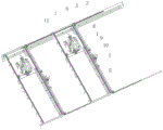
FIG. 1 is a schematic perspective view of an omnidirectional tube laying mechanism of the present invention;
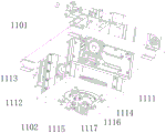
FIG. 2 is a schematic perspective view of the tube laying assembly of the present invention;
FIG. 3 is a schematic perspective view of the other direction of the tube laying assembly of the present invention;
figure 4 is a side view of the tube application assembly of the present invention.
Detailed Description
The following detailed description of the preferred embodiments of the present invention will be provided in conjunction with the accompanying drawings, so that the advantages and features of the present invention can be more easily understood by those skilled in the art, and the protection scope of the present invention can be clearly and clearly defined. In the present invention, directional terms such as "up", "down", "front", "back", "left", "right", "top", "bottom", etc. refer to directions of the attached drawings only. Accordingly, the directional terms used are used for describing and understanding the present invention, and are not used for limiting the present invention.
The omnibearing pipe laying mechanism shown in fig. 1 is used for receiving a pipe, bending the pipe and laying the pipe on the surface of a plate, and comprises a transverse guide rail 2, a longitudinal guide rail 7 arranged on the transverse guide rail 2, a transverse driving piece for driving the longitudinal guide rail 7 to move along the transverse guide rail 2, a pipe laying assembly 11 arranged on the longitudinal guide rail 7 and a longitudinal driving piece for driving the pipe laying assembly 11 to move along the longitudinal guide rail 7. Be provided with first rack 3 on transverse guide 2, 7 one side of longitudinal rail is provided with first pivot 5, and 5 both ends of first pivot are provided with first gear 6 respectively, and first gear 6 meshes with first rack 3 mutually, transverse driving spare is motor 4, and motor 4 is connected with first pivot 5, and motor 4 can drive first pivot 5 rotatory, and first gear 6 on the first pivot 5 rolls along first rack 3 to drive whole longitudinal rail 7 along 2 lateral shifting of transverse guide. The utility model discloses a pipe laying machine, including longitudinal rail 7, lay pipe assembly 11, motor 1, longitudinal driving piece, first gear 9, second rack 8, longitudinal rail 7 is last to be provided with second rack 8, one side of pipe laying subassembly 11 is provided with second pivot 10, and second pivot 10 both ends are provided with second gear 9, and second gear 9 meshes with second rack 8 mutually, the longitudinal driving piece is motor 1, and motor 1 is connected with second pivot 10, and motor 1 can drive second pivot 10 rotatory, and second gear 9 on the second pivot 10 rolls along second rack 8 to drive whole pipe laying subassembly 11 along longitudinal rail 7 longitudinal movement.
The tube application assembly shown in fig. 2-4 comprises a moving seat 1101, a tube guiding module, a tube passage 1119, an elevating seat 1102, an elevating guide rail 1108, an elevating seat driving member, a turntable 1114, a turntable driving member and a tube application module, wherein the moving seat 1101 is arranged on a longitudinal guide rail, the bottom surface of the moving seat 1101 is provided with four sliding blocks sliding along the longitudinal guide rail, the tube guiding module is arranged at the top end of the moving seat, the tube guiding module comprises an inlet pipe port 1118, a positioning wheel 1104, a clamping wheel 1103, a positioning wheel driving member and a clamping wheel driving member, the positioning wheel driving member is a motor 1107 capable of driving the positioning wheel 1104 to rotate, the clamping wheel 1103 is correspondingly arranged at the right side of the positioning wheel 1104, a clamping guide passage is formed between the clamping wheel 1103 and the positioning wheel 1104, the inlet pipe 1118 is correspondingly arranged above the clamping guide passage, the clamping wheel driving member is located in a cylinder 1105, and the cylinder 1105 can drive the clamping wheel 1103 to move along the guide frame 1106, thereby clamping or loosening the pipe in the clamping guide channel, the motor 1107 drives the positioning wheel 1104 to rotate to realize traction, the pipe channel 1119 is correspondingly arranged below the clamping guide channel, the lifting guide tracks 1108 are two groups and are fixed on the bottom surface of the movable seat 1101, the lifting seat 1102 is correspondingly provided with two groups of lifting guide rails 1109, the lifting guide rails 1109 are in sliding connection with the lifting guide tracks 1108, the lifting guide rails 1109 are provided with third racks 1113, the movable seat 1101 is provided with a third rotating shaft, the third rotating shaft is provided with a third gear 1112, the third gear 1112 is meshed with the third rack 1113, the lifting seat driving part is a motor 1111 and is connected with the third rotating shaft, the motor 1111 can drive the third rotating shaft to rotate, the third gear 1112 on the third rotating shaft is rotated to drive the lifting seat 1102 to lift along the lifting guide tracks 1108, the rotary disc 1114 is arranged on the lifting seat 1102, the turntable driving member drives the turntable 1114 to rotate through the gear plate 1110. The tube application module is arranged at the bottom end of the rotary disc 1114, the tube application module comprises an installation plate 1115, a tube application positioning wheel 1120, a tube application pinch roller 1121 and a pinch roller driving piece, the tube application positioning wheel 1120, the tube application pinch roller 1121 and the pinch roller driving piece are arranged on the installation plate 1115, a plurality of springs 1122 and guide columns are arranged between the installation plate 1115 and the rotary disc 1114, the installation plate 1115 is elastically connected with the tube application positioning wheel 1114 through the springs 1122, the springs 1122 can play a role in buffering, the tube application pinch roller 1121 is correspondingly arranged on one side of the tube application positioning wheel 1120, a positioning channel is formed between the tube application pinch roller 1121 and the tube application positioning wheel 1120, the pinch roller driving piece is an air cylinder 1124, the air cylinder 1124 is connected with the tube application positioning wheel 1120 through a connecting rod 1123, and the air cylinder 1124 can drive the tube application pinch roller 1121 to move so as to clamp or loosen tubes in the positioning channel. In addition, two groups of dotting assemblies used for fastening the pipe fitting and the plate are further arranged at the bottom end of the mounting plate 1115, each dotting assembly comprises a dotting cylinder 1116 and a push rod 1117, the push rods 1117 are correspondingly arranged on one side of the pipe laying positioning wheel 1120, and the dotting cylinders 1116 can drive the push rods 1117 to stretch and retract.
During processing, as shown in fig. 1-4, a pipe is guided through a pipe inlet 1118 and enters between the clamping wheel 1103 and the positioning wheel 1104, the air cylinder 1105 drives the clamping wheel 1103 to move leftwards, so that the two wheels clamp the pipe, the motor 1107 drives the positioning wheel 1104 to rotate, the pipe can be pulled and fed into the lower part, the pipe enters between the pipe laying positioning wheel 1120 and the pipe laying pressing wheel 1121 through the pipe passage 1119, and the air cylinder 1124 drives the pipe laying pressing wheel 1121 to swing to press the pipe tightly, so that pipe laying can be started; motor 1111 passes through third gear 1112 and the cooperation of third rack 1113, drive whole lift seat 1102 and descend to fixed position, pipe laying positioning wheel 1120, pipe laying pinch roller 1121 laminates with the panel surface of below mutually, tubular product gets into in the recess of panel this moment, motor 1 and motor 4 pass through the gear, rack cooperation drive pipe laying subassembly is horizontal, longitudinal movement, can lay the pipe gradually, and when tubular product laid to recess corner, motor drive carousel 1114 rotates 180 degrees gradually, can bend tubular product into the circular arc gradually and lay the pipe, when laying the pipe, two cylinders 1116 drive two push rods 1117 simultaneously and constantly punch to the recess both sides of panel, make the recess edge inwards expand, get up "the parcel" tubular product, can realize tubular product and panel relatively fixed, avoid tubular product and panel pine to take off.
It should be noted that, in the present invention, the power member, the driving member, etc. may be an oil cylinder, an air cylinder, a motor, an electric cylinder, etc. to realize the motion through a connecting rod, a connecting shaft, etc., and are not limited to the structure in the specification and the drawings.
The utility model discloses the part that does not relate to all is the same with prior art or can adopt prior art to realize.
In addition, in the description of the embodiments of the present invention, unless otherwise explicitly specified or limited, the terms "mounted," "connected," "disposed," "provided," and the like are to be construed broadly and may be, for example, fixedly connected, detachably connected, or integrally connected; can be mechanically or electrically connected; they may be connected directly or indirectly through intervening media, or they may be interconnected between two elements. The specific meaning of the above terms in the present invention can be understood in specific cases to those skilled in the art.
The above-mentioned embodiments only represent some embodiments of the present invention, and the description thereof is specific and detailed, but not to be construed as limiting the scope of the present invention. It should be noted that, for those skilled in the art, without departing from the spirit of the present invention, several variations and modifications can be made, which are within the scope of the present invention.
Claims (8)
1. An all-round pipe laying mechanism which characterized in that: the pipe laying assembly comprises a moving seat, a pipe guiding module, a lifting seat, a lifting guide rail, a lifting seat driving part, a turntable driving part and a pipe laying module, wherein the moving seat is arranged on the longitudinal guide rail, the pipe guiding module is arranged on the moving seat, the pipe guiding module comprises a positioning wheel, a clamping wheel, a positioning wheel driving part and a clamping wheel driving part, the positioning wheel driving part can drive the positioning wheel to rotate, the clamping wheel is correspondingly arranged on one side of the positioning wheel, a clamping guide channel is formed between the clamping wheel and the positioning wheel, and the clamping wheel driving part can drive the clamping wheel to move so as to clamp or loosen a pipe in the clamping guide channel, the pipe laying module comprises a mounting plate, a laying positioning wheel, a laying pressing wheel and a pressing wheel driving part, wherein the laying positioning wheel, the laying pressing wheel and the laying positioning wheel are arranged on the mounting plate correspondingly, a positioning channel is formed between the laying pressing wheel and the laying positioning wheel, and the pressing wheel driving part can drive the laying pressing wheel to move so as to clamp or loosen a pipe fitting in the positioning channel.
2. The omni-directional tube application mechanism according to claim 1, wherein: the top end of the pipe fitting guide module is provided with a pipe inlet, and the bottom end of the pipe fitting guide module is provided with a pipe fitting channel.
3. The omni-directional tube application mechanism according to claim 1, wherein: the transverse guide rail is provided with a first rack, one side of the longitudinal guide rail is provided with a first rotating shaft, two ends of the first rotating shaft are provided with first gears, the first gears are meshed with the first rack, the transverse driving piece is connected with the first rotating shaft, and the transverse driving piece can drive the first rotating shaft to rotate so as to drive the longitudinal guide rail to move transversely along the transverse guide rail.
4. The omni-directional tube application mechanism according to claim 3, wherein: the vertical guide rail is provided with a second rack, one side of the moving seat is provided with a second rotating shaft, two ends of the second rotating shaft are provided with second gears, the second gears are meshed with the second racks, the vertical driving piece is connected with the second rotating shaft, and the vertical driving piece can drive the second rotating shaft to rotate so as to drive the moving seat to move vertically along the vertical guide rail.
5. The omni-directional tube application mechanism according to claim 1, wherein: the lifting seat is provided with a lifting guide rail, the lifting guide rail slides along the lifting guide rail, a third rack is arranged on the lifting guide rail, a third rotating shaft is arranged on the moving seat, a third gear is arranged on the third rotating shaft and meshed with the third rack, the lifting seat driving piece is connected with the third rotating shaft, and the lifting seat driving piece can drive the third rotating shaft to rotate so as to drive the lifting seat to lift along the lifting guide rail.
6. The omni-directional tube application mechanism according to claim 1, wherein: be provided with the fluted disc on the carousel, the carousel driving piece passes through fourth pivot drive fluted disc and rotates.
7. The omni-directional tube application mechanism according to claim 1, wherein: and a spring is arranged between the mounting plate and the turntable, and the mounting plate is elastically connected with the turntable through the spring.
8. The omni-directional tube application mechanism according to claim 1, wherein: the pipe laying and positioning device is characterized in that a dotting assembly used for fastening the pipe fitting and the plate is further arranged on the mounting plate, the dotting assembly comprises a dotting cylinder and a push rod, the push rod is correspondingly arranged on one side of the pipe laying and positioning wheel, and the dotting cylinder can drive the push rod to stretch.
Priority Applications (1)
| Application Number | Priority Date | Filing Date | Title |
|---|---|---|---|
| CN202121239591.XU CN214976899U (en) | 2021-06-03 | 2021-06-03 | Omnibearing pipe laying mechanism |
Applications Claiming Priority (1)
| Application Number | Priority Date | Filing Date | Title |
|---|---|---|---|
| CN202121239591.XU CN214976899U (en) | 2021-06-03 | 2021-06-03 | Omnibearing pipe laying mechanism |
Publications (1)
| Publication Number | Publication Date |
|---|---|
| CN214976899U true CN214976899U (en) | 2021-12-03 |
Family
ID=79085320
Family Applications (1)
| Application Number | Title | Priority Date | Filing Date |
|---|---|---|---|
| CN202121239591.XU Active CN214976899U (en) | 2021-06-03 | 2021-06-03 | Omnibearing pipe laying mechanism |
Country Status (1)
| Country | Link |
|---|---|
| CN (1) | CN214976899U (en) |
-
2021
- 2021-06-03 CN CN202121239591.XU patent/CN214976899U/en active Active
Similar Documents
| Publication | Publication Date | Title |
|---|---|---|
| CN113275423A (en) | Omnibearing pipe laying mechanism | |
| CN101559442B (en) | Sheet-stretching machine | |
| CN115026164A (en) | Arc bending equipment for forming A column of vehicle body | |
| CN113443430A (en) | Feeding device for plate processing | |
| CN214976899U (en) | Omnibearing pipe laying mechanism | |
| CN202239387U (en) | Multi-specification simple spring-winding machine | |
| CN201997583U (en) | Bender | |
| CN113334094B (en) | Full-automatic pipe laying device for radiation system | |
| CN211915058U (en) | Battery module plastic pre-compaction device | |
| CN214922083U (en) | Plate surface pipe laying mechanism | |
| CN113714349B (en) | Horizontal type four-corner frame bending machine and production method thereof | |
| CN213495761U (en) | Bending device for sheet metal forming processing and convenient to adjust bending angle | |
| CN102172687B (en) | Lifting mechanism of bender | |
| CN111823604A (en) | Hot melt compounding machine | |
| CN114309173A (en) | Bending device for high-quality special steel processing and bending method thereof | |
| CN111215543B (en) | Plate bending machine | |
| CN216095756U (en) | Bending mechanism of horizontal four-corner frame bending machine | |
| CN212555095U (en) | Hot melt compounding machine | |
| CN215061396U (en) | Wire pressing device for producing LED full-color light bar | |
| CN212497991U (en) | Grooving machine for producing color steel sandwich heat-insulation air duct | |
| CN219823116U (en) | Cloth feeding device | |
| CN219254720U (en) | Screw taking and placing mechanism and automatic screw locking machine with same | |
| CN203359501U (en) | Auxiliary discharging machine | |
| CN210816838U (en) | Shell bending device for processing storage battery | |
| CN219520283U (en) | Novel die stamping feeding device |
Legal Events
| Date | Code | Title | Description |
|---|---|---|---|
| GR01 | Patent grant | ||
| GR01 | Patent grant |