CN214952051U - High-precision dynamometer for spring detection - Google Patents
High-precision dynamometer for spring detection Download PDFInfo
- Publication number
- CN214952051U CN214952051U CN202120575168.0U CN202120575168U CN214952051U CN 214952051 U CN214952051 U CN 214952051U CN 202120575168 U CN202120575168 U CN 202120575168U CN 214952051 U CN214952051 U CN 214952051U
- Authority
- CN
- China
- Prior art keywords
- sliding
- spring
- magnet
- guide
- rod
- Prior art date
- Legal status (The legal status is an assumption and is not a legal conclusion. Google has not performed a legal analysis and makes no representation as to the accuracy of the status listed.)
- Active
Links
Images


Abstract
The utility model discloses a spring detects uses high accuracy dynamometer, including base, threaded rod, bracing piece, scale and pressure sensor, the spout has been seted up to the inside of base, the inner wall bottom dress of guide way has inlayed first magnet, and the inboard of guide way is provided with the telescopic link to the side of telescopic link is provided with the guide block, the last surface bolted fixation of base has the guide post, and the outside mark of guide post has the scale, the cylinder is installed to the top bolt of roof, and the below bolt fastening of cylinder has the fly leaf, the lower surface mounting of fly leaf has pressure sensor, and pressure sensor's lower extreme bonds there is the push pedal. This high accuracy dynamometer for spring detects can conveniently carry out spacing support to not unidimensional spring, avoids taking place crooked among the spring compression process to improve and detect the precision, be provided with a plurality of stations simultaneously, detection efficiency is higher, the contrastive analysis of being convenient for.
Description
Technical Field
The utility model relates to a spring production technical field specifically is a spring detects uses high accuracy dynamometer.
Background
The spring is the most common mechanical part, and can convert the external applied force into elastic potential energy and internal energy, so the spring is widely applied to the field of damping devices, the spring is generally made of elastic materials such as spring steel, and in the spring production and processing process, a dynamometer needs to be used for detecting the elastic performance of the spring, but the existing dynamometer for spring detection still has some defects, such as:
1. the circumference diameters of springs with different production specifications are different, but the conventional dynamometer for detecting the springs is fixed in structure, so that the springs with different sizes are inconvenient to limit and fix, the applicability of the device is low, and certain use defects exist;
2. most of the existing dynamometers for spring detection adopt a single-station mode for detection, so that the device can only measure the force of a single spring at a time, the detection efficiency of the device is reduced, meanwhile, the comparative test of the elastic properties of springs made of different materials is inconvenient, and the practicability of the device is reduced;
we have therefore proposed a high precision force gauge for spring testing in order to solve the problems set out above.
SUMMERY OF THE UTILITY MODEL
An object of the utility model is to provide a spring detects uses high accuracy dynamometer to solve the inconvenient problem that detects, detection efficiency hangs down of carrying out spacing test and inconvenient contrast to the not unidimensional spring of carrying on of present market dynamometry appearance for spring detection that above-mentioned background art provided.
In order to achieve the above object, the utility model provides a following technical scheme: a high-precision dynamometer for spring detection comprises a base, a threaded rod, a supporting rod, a graduated scale and a pressure sensor, wherein a sliding groove is formed in the base, a bearing at the inner side of the sliding groove is connected with the threaded rod, a servo motor is arranged at the middle position in the base, a sliding block is arranged at the inner side of the sliding groove, the upper end of the sliding block is fixedly connected with the supporting rod, a guide groove is formed in the supporting rod, a first magnet is embedded at the bottom of the inner wall of the guide groove, a telescopic rod is arranged at the inner side of the guide groove, a guide block is arranged on the side surface of the telescopic rod, a guide column is fixed on the upper surface of the base through a bolt, the graduated scale is marked on the outer side of the guide column, a top plate is fixed on the upper end of the guide column through a bolt, an air cylinder is installed on the top of the top plate through a bolt, a movable plate is fixed on the lower side of the air cylinder through a bolt, and a sliding sleeve is arranged on the outer side of the movable plate, the lower surface of fly leaf installs pressure sensor, and pressure sensor's lower extreme bonding has the push pedal.
Preferably, the sliding grooves are distributed at equal angles relative to the base, and bevel gear assemblies are connected between threaded rods on the inner sides of the sliding grooves and the output end of the servo motor.
Preferably, the sliding block and the sliding groove form a clamping sliding structure, the sliding block is in threaded connection with the threaded rod, and the thread turning directions of the two ends of the threaded rod are opposite.
Preferably, the telescopic link passes through the guide block and constitutes block sliding structure with the guide way, and the telescopic link flushes each other with one side between them of bracing piece to the bracing piece corresponds each other with the position of push pedal.
Preferably, the lower extreme dress of telescopic link has inlayed second magnet, and the magnetic pole between second magnet and the first magnet is opposite to the telescopic link passes through the magnetic force effect between second magnet and the first magnet and constitutes elastic telescopic structure with the bracing piece.
Preferably, the sliding sleeve and the guide post form a sliding sleeve structure, and the outside of the sliding sleeve is provided with a graduated needle, and the graduated needle is attached to the graduated scale.
Compared with the prior art, the beneficial effects of the utility model are that: the high-precision dynamometer is used for spring detection;
1. the device is provided with the threaded rod, the supporting rod and the telescopic rod, the position of the supporting rod can be conveniently adjusted by rotating the threaded rod, so that the supporting rod can support springs with different sizes, meanwhile, the supporting rod and the telescopic rod which can elastically stretch can be used for supporting the springs all the time in the detection process of the device, the situation that the springs are inclined in the compression process of the springs to influence the detection effect is avoided, the device can support the springs with different sizes through the structure, the situation that the springs are inclined in the compression process of the springs is avoided, and the application range and the detection effect of the dynamometer are effectively improved;
2. be provided with sliding sleeve and push pedal, through removing the fly leaf, can be so that a plurality of push pedals extrude simultaneously and wait to detect the spring, improved the detection efficiency of device, the fly leaf removes the in-process simultaneously and can drive the sliding sleeve and slide along the guide post for the scale needle can accurately measure the volume of compression that detects the detection spring, and the device of being convenient for contrasts the detection to the spring, has effectively improved the detection efficiency and the practicality of device through this structure.
Drawings
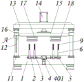
FIG. 1 is a schematic view of the main sectional structure of the present invention;
FIG. 2 is a side sectional view of the strut of the present invention;
FIG. 3 is a schematic view of the telescopic rod of the present invention;
fig. 4 is a schematic view of the movable plate of the present invention in a bottom view;
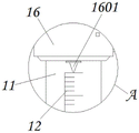
fig. 5 is an enlarged schematic view of a portion a in fig. 1 according to the present invention.
In the figure: 1. a base; 2. a chute; 3. a threaded rod; 4. a servo motor; 401. a bevel gear assembly; 5. a slider; 6. a support bar; 7. a guide groove; 8. a first magnet; 9. a telescopic rod; 901. a second magnet; 10. a guide block; 11. a guide post; 12. a graduated scale; 13. a top plate; 14. a cylinder; 15. a movable plate; 16. a sliding sleeve; 1601. a scale needle; 17. a pressure sensor; 18. a push plate.
Detailed Description
The technical solutions in the embodiments of the present invention will be described clearly and completely with reference to the accompanying drawings in the embodiments of the present invention, and it is obvious that the described embodiments are only some embodiments of the present invention, not all embodiments. Based on the embodiments in the present invention, all other embodiments obtained by a person skilled in the art without creative work belong to the protection scope of the present invention.
Referring to fig. 1-5, the present invention provides a technical solution: a high-precision dynamometer for spring detection comprises a base 1, a sliding groove 2, a threaded rod 3, a servo motor 4, a bevel gear component 401, a sliding block 5, a supporting rod 6, a guide groove 7, a first magnet 8, a telescopic rod 9, a second magnet 901, a guide block 10, a guide post 11, a graduated scale 12, a top plate 13, an air cylinder 14, a movable plate 15, a sliding sleeve 16, a graduated needle 1601, a pressure sensor 17 and a push plate 18, wherein the sliding groove 2 is formed in the base 1, the inner side of the sliding groove 2 is connected with the threaded rod 3 through a bearing, the servo motor 4 is arranged at the middle position in the base 1, the sliding block 5 is arranged on the inner side of the sliding groove 2, the supporting rod 6 is fixedly connected to the upper end of the sliding block 5, the guide groove 7 is formed in the supporting rod 6, the first magnet 8 is embedded at the bottom of the inner wall of the guide groove 7, the telescopic rod 9 is arranged on the inner side of the guide groove 7, and the guide block 10 is arranged on the side surface of the telescopic rod 9, a guide column 11 is fixed on the upper surface of the base 1 through a bolt, a graduated scale 12 is marked on the outer side of the guide column 11, a top plate 13 is fixed on the upper end of the guide column 11 through a bolt, an air cylinder 14 is installed on the top of the top plate 13 through a bolt, a movable plate 15 is fixed on the lower side of the air cylinder 14 through a bolt, a sliding sleeve 16 is arranged on the outer side of the movable plate 15, a pressure sensor 17 is installed on the lower surface of the movable plate 15, and a push plate 18 is bonded on the lower end of the pressure sensor 17;
the sliding chute 2 is distributed in an equal angle mode relative to the base 1, a bevel gear assembly 401 is connected between the threaded rod 3 on the inner side of the sliding chute 2 and the output end of the servo motor 4, and the servo motor 4 is started, so that the servo motor 4 can drive the plurality of threaded rods 3 to synchronously rotate through the bevel gear assembly 401, and the device is convenient to operate;
the sliding block 5 and the sliding groove 2 form a clamping sliding structure, the sliding block 5 is in threaded connection with the threaded rod 3, the thread turning directions of two ends of the threaded rod 3 are opposite, and the position of the sliding block 5 in the sliding groove 2 can be conveniently adjusted by rotating the threaded rod 3, so that the supporting rod 6 can be attached to a spring with different sizes;
the telescopic rod 9 and the guide groove 7 form a clamping sliding structure through the guide block 10, one surfaces of the telescopic rod 9 and the support rod 6 are flush with each other, the positions of the support rod 6 and the push plate 18 correspond to each other, and the support rod 6 and the telescopic rod 9 can support springs with different sizes by adjusting the position of the support rod 6, so that the inaccurate detection effect caused by deflection of the springs during compression is avoided;
the lower end of the telescopic rod 9 is embedded with a second magnet 901, the magnetic poles of the second magnet 901 are opposite to those of the first magnet 8, the telescopic rod 9 and the supporting rod 6 form an elastic telescopic structure under the magnetic action of the second magnet 901 and the first magnet 8, the telescopic rod 9 and the detection spring can be synchronously stretched through the elastic telescopic structure, the supporting rod 6 and the telescopic rod 9 can support the detection spring in real time, and meanwhile, the influence on normal downward moving extrusion of the push plate 18 can be avoided;
sliding sleeve 16 constitutes the slip muff-coupling structure with guide post 11, and the outside of sliding sleeve 16 is provided with scale needle 1601 to scale needle 1601 laminates in scale 12, through along guide post 11 slip sliding sleeve 16, can play the guide effect to fly leaf 15, and the scale needle 1601 in the sliding sleeve 16 outside can accurately measure the deformation volume of waiting to detect the spring simultaneously, and the device of being convenient for carries out contrastive analysis.
The working principle is as follows: when the high-precision dynamometer for spring detection is used, firstly, as shown in fig. 1-4, a plurality of springs to be detected are sleeved outside supporting rods 6 at different positions, then a servo motor 4 is started, the servo motor 4 drives a plurality of threaded rods 3 to synchronously rotate through a bevel gear component 401, the threaded rods 3 can drive a slider 5 to slide and adjust along a sliding groove 2, so that the supporting rods 6 and telescopic rods 9 can adjust the positions of the supporting rods 6 and telescopic rods 9, the supporting rods 6 and telescopic rods 9 can effectively support the springs to be detected at different sizes, the detection result is prevented from being influenced by deflection in the spring compression detection process, then a control cylinder 14 pushes a movable plate 15 to move downwards, a sliding sleeve 16 slides along a guide column 11, when a push plate 18 contacts the telescopic rods 9 and the springs to be detected, the movable plate 15 continues to move downwards, and at the moment, the push plate 18 can extrude, Compressing the spring to be detected, and simultaneously, elastically sliding the telescopic rod 9 along the guide groove 7 under the magnetic force action of the first magnet 8 and the second magnet 901, so that the supporting rod 6 and the telescopic rod 9 can always keep supporting the spring to be detected, and at the moment, the pressure sensor 17 can be subjected to the elastic force action of the spring to be detected and the mutual repulsion magnetic force action of the first magnet 8 and the second magnet 901, so that the elastic force of the spring can be accurately detected (since the compression amount of the spring to be detected is equal to the displacement distance of the telescopic rod 9, the magnetic force between the first magnet 8 and the second magnet 901 can be accurately detected, the elastic force of the spring can be accurately detected through the pressure sensor 17, and data calculation can be completed by a computer);
as shown in fig. 1 and 5, when the movable plate 15 is moved and adjusted, the sliding sleeve 16 can drive the scale needle 1601 to slide on the outer side of the movable plate 15, and at this time, the scale needle 1601 can accurately measure the deformation of the spring to be detected, so as to facilitate the detection of the distance of data, improve the convenience of the device, and complete a series of operations.
Those not described in detail in this specification are within the skill of the art.
Although the present invention has been described in detail with reference to the foregoing embodiments, it will be apparent to those skilled in the art that modifications may be made to the embodiments or portions thereof without departing from the spirit and scope of the invention.
Claims (6)
1. The utility model provides a spring detects uses high accuracy dynamometer, includes base (1), threaded rod (3), bracing piece (6), scale (12) and pressure sensor (17), its characterized in that: the improved structure of the automobile seat is characterized in that a sliding groove (2) is formed in the base (1), a threaded rod (3) is connected to an inner side bearing of the sliding groove (2), a servo motor (4) is arranged at the middle position in the base (1), a sliding block (5) is arranged on the inner side of the sliding groove (2), a supporting rod (6) is fixedly connected to the upper end of the sliding block (5), a guide groove (7) is formed in the supporting rod (6), a first magnet (8) is embedded at the bottom of the inner wall of the guide groove (7), a telescopic rod (9) is arranged on the inner side of the guide groove (7), a guide block (10) is arranged on the side face of the telescopic rod (9), a guide column (11) is fixed on the upper surface of the base (1) through a bolt, a scale (12) is marked on the outer side of the guide column (11), a top plate (13) is fixed on the upper end of the guide column (11), and a cylinder (14) is installed on the top bolt of the top plate (13), and a movable plate (15) is fixed on the lower portion of the air cylinder (14) through a bolt, a sliding sleeve (16) is arranged on the outer side of the movable plate (15), a pressure sensor (17) is installed on the lower surface of the movable plate (15), and a push plate (18) is bonded to the lower end of the pressure sensor (17).
2. The high-precision force measuring instrument for spring detection according to claim 1, wherein: the sliding chute (2) is distributed at equal angles relative to the base (1), and a bevel gear component (401) is connected between the threaded rod (3) on the inner side of the sliding chute (2) and the output end of the servo motor (4).
3. The high-precision force measuring instrument for spring detection according to claim 1, wherein: the sliding block (5) and the sliding groove (2) form a clamping sliding structure, the sliding block (5) is in threaded connection with the threaded rod (3), and the thread turning directions of the two ends of the threaded rod (3) are opposite.
4. The high-precision force measuring instrument for spring detection according to claim 1, wherein: the telescopic rod (9) and the guide groove (7) form a clamping sliding structure through the guide block (10), one surfaces of the telescopic rod (9) and the support rod (6) are flush with each other, and the positions of the support rod (6) and the push plate (18) correspond to each other.
5. The high-precision force measuring instrument for spring detection according to claim 1, wherein: the lower end of the telescopic rod (9) is embedded with a second magnet (901), the magnetic poles of the second magnet (901) and the first magnet (8) are opposite, and the telescopic rod (9) and the support rod (6) form an elastic telescopic structure under the action of the magnetic force of the second magnet (901) and the first magnet (8).
6. The high-precision force measuring instrument for spring detection according to claim 1, wherein: sliding sleeve (16) and guide post (11) constitute the slip cup joint structure, and the outside of sliding sleeve (16) is provided with scale needle (1601) to scale needle (1601) laminating in scale (12).
Priority Applications (1)
| Application Number | Priority Date | Filing Date | Title |
|---|---|---|---|
| CN202120575168.0U CN214952051U (en) | 2021-03-22 | 2021-03-22 | High-precision dynamometer for spring detection |
Applications Claiming Priority (1)
| Application Number | Priority Date | Filing Date | Title |
|---|---|---|---|
| CN202120575168.0U CN214952051U (en) | 2021-03-22 | 2021-03-22 | High-precision dynamometer for spring detection |
Publications (1)
| Publication Number | Publication Date |
|---|---|
| CN214952051U true CN214952051U (en) | 2021-11-30 |
Family
ID=79041619
Family Applications (1)
| Application Number | Title | Priority Date | Filing Date |
|---|---|---|---|
| CN202120575168.0U Active CN214952051U (en) | 2021-03-22 | 2021-03-22 | High-precision dynamometer for spring detection |
Country Status (1)
| Country | Link |
|---|---|
| CN (1) | CN214952051U (en) |
-
2021
- 2021-03-22 CN CN202120575168.0U patent/CN214952051U/en active Active
Similar Documents
| Publication | Publication Date | Title |
|---|---|---|
| CN108827193B (en) | Detection device for accurately detecting flatness of template | |
| CN211503961U (en) | Concrete material apparent crack monitoring and detecting device | |
| CN213021356U (en) | Novel contact height detection machine | |
| CN105043335B (en) | A kind of nozzle ring aisle spare measuring instrument | |
| CN214952051U (en) | High-precision dynamometer for spring detection | |
| CN210834520U (en) | Sclerometer calibrating device | |
| CN108759752A (en) | A kind of calibrating installation for displacement sensor | |
| CN209706694U (en) | A kind of patch positioning device of strain gauge transducer | |
| CN102494600B (en) | Multidimension measuring apparatus of high speed processing handle | |
| CN218916303U (en) | Metal surface detects roughness appearance | |
| CN205520741U (en) | A support for measure lathe main shaft diameter runout | |
| CN210834453U (en) | Rubber plastic elongation tester | |
| CN210374892U (en) | Building material size detection device | |
| CN109100231B (en) | Elasticity detection equipment for vitrified micro bubble heat preservation concrete after high temperature action | |
| CN208476188U (en) | A kind of measuring instrument for vehicle brake inner spring component | |
| CN208313260U (en) | Displacement transducer calibration device | |
| CN220322334U (en) | Height verification tool | |
| CN206177258U (en) | Flat straightness measuring device's rail brackets | |
| CN220454617U (en) | Sensor processing detection table | |
| CN220418779U (en) | Anti-falling performance detection device | |
| CN205958362U (en) | Novel compression testing machine | |
| CN216386322U (en) | Shock absorber performance detection device | |
| CN220170211U (en) | Device for detecting piston ring inclined plane | |
| CN212844688U (en) | Indentation deformation tool | |
| CN217483415U (en) | Shaft hub assembly angle measuring instrument |
Legal Events
| Date | Code | Title | Description |
|---|---|---|---|
| GR01 | Patent grant | ||
| GR01 | Patent grant |