CN214926885U - Multi-layer drip irrigation pipe co-extrusion composite machine head - Google Patents
Multi-layer drip irrigation pipe co-extrusion composite machine head Download PDFInfo
- Publication number
- CN214926885U CN214926885U CN202023104335.8U CN202023104335U CN214926885U CN 214926885 U CN214926885 U CN 214926885U CN 202023104335 U CN202023104335 U CN 202023104335U CN 214926885 U CN214926885 U CN 214926885U
- Authority
- CN
- China
- Prior art keywords
- sub
- extrusion
- outer sleeve
- groove
- channel
- Prior art date
- Legal status (The legal status is an assumption and is not a legal conclusion. Google has not performed a legal analysis and makes no representation as to the accuracy of the status listed.)
- Active
Links
Images


Abstract
The utility model provides a pipe co-extrusion composite aircraft nose is driped irrigation to multilayer, include: the extrusion molding machine comprises a machine shell, a mold core, an opening mold, an inner sleeve and an outer sleeve, wherein a first feed inlet and a second feed inlet are formed in the machine shell, an installation channel is formed in the machine shell, the opening mold is provided with an extrusion opening, the opening mold is arranged at the front end part of the machine shell, the outer sleeve is arranged in the installation channel, the inner sleeve is arranged in the outer sleeve, and the mold core is arranged in the inner sleeve and inserted into the extrusion opening; an extrusion space is formed between the mold core and the extrusion port, a first extrusion channel is formed between the outer sleeve and the inner wall of the mounting channel, a second extrusion channel is formed between the inner sleeve and the outer sleeve, the first extrusion channel is sleeved outside the second extrusion channel, the front end part of the first extrusion channel and the front end part of the second extrusion channel are respectively communicated with the extrusion space, the first feed port is communicated with the first extrusion channel, and the second feed port is communicated with the second extrusion channel. The processing quality of the drip irrigation pipe is improved through the multilayer drip irrigation pipe co-extrusion composite extrusion equipment.
Description
Technical Field
The utility model relates to the technical field of machinery, especially, relate to a pipe is driped irrigation to multilayer crowded composite aircraft nose altogether.
Background
Water-saving irrigation is a main measure adopted by countries in the world for developing modern agriculture, drip irrigation is an advanced high-standard irrigation technology in water-saving irrigation, and drip irrigation pipes have the advantages of water saving, yield increasing, high efficiency, environmental protection and the like and are widely applied to fields, greenhouses, ecological gardens and urban landscaping. The drip irrigation pipe body is usually processed by adopting an extrusion mode, and is extruded by an extruder head to form the drip irrigation pipe. However, because the whole pipe wall of the drip irrigation pipe is thick, the internal pressure of the machine head is high in the extrusion process, and the mold core in the machine head is easy to deviate, so that the wall thickness of the drip irrigation pipe is not uniform, and the processing quality of the drip irrigation pipe is low. How to design a technique that improves drip irrigation pipe processingquality is the utility model discloses the technical problem that will solve.
Disclosure of Invention
The utility model provides a pipe crowded compound aircraft nose altogether is driped irrigation to multilayer realizes driping irrigation the pipe through the multilayer and crowded compound aircraft nose altogether and improves the processingquality who drips irrigation the pipe.
The utility model provides a pipe co-extrusion composite aircraft nose is driped irrigation to multilayer, include: the die comprises a machine shell, a die core, a die opening, an inner sleeve and an outer sleeve, wherein a first feed inlet and a second feed inlet are formed in the machine shell, an installation channel is formed in the machine shell, the die opening is provided with an extrusion opening, the die opening is arranged at the front end part of the machine shell, the outer sleeve is arranged in the installation channel, the inner sleeve is arranged in the outer sleeve, and the die core is arranged in the inner sleeve and inserted into the extrusion opening; the die core with extrude and form between the mouth and extrude the space, the overcoat with form first extrusion passageway between the inner wall of installation passageway, the endotheca with form the second between the overcoat and extrude the passageway, first extrusion passageway cover is in the outside that the passageway was extruded to the second, the first front end portion of extruding the passageway with the second is extruded the front end portion of passageway and is communicate respectively extrude the space, first feed inlet with first extrusion passageway intercommunication, the second feed inlet with the passageway intercommunication is extruded to the second.
Further, the outer sleeve comprises a first sub outer sleeve and a second sub outer sleeve, the second sub outer sleeve is arranged in the first sub outer sleeve, the first extrusion channel is formed between the first sub outer sleeve and the inner wall of the installation channel, the second extrusion channel is formed between the inner sleeve and the second sub outer sleeve, and a third extrusion channel is formed between the first sub outer sleeve and the second sub outer sleeve; the casing is provided with a third feed port, the front end part of the third extrusion channel is communicated with the extrusion space, and the third feed port is communicated with the third extrusion channel.
Further, the front end part of the mounting channel is provided with a conical opening.
Further, along the material flow direction, the thickness of the first extrusion channel, the thickness of the second extrusion channel and the thickness of the third extrusion channel are gradually increased.
Furthermore, the outer wall of the first sub-outer sleeve is provided with a first spiral groove, the outer wall of the inner sleeve is provided with a second spiral groove, and the outer wall of the second sub-outer sleeve is provided with a third spiral groove.
Further, along the material flow direction, the depth of first spiral groove, second spiral groove and third spiral groove diminishes gradually.
Furthermore, the outer wall of the first sub-outer sleeve positioned at the rear end is tightly attached to the inner wall of the installation channel, and the installation channel covers part of the groove body of the first spiral groove positioned at the rear end; the outer wall of the second sub-outer sleeve positioned at the rear end is tightly attached to the inner wall of the first sub-outer sleeve, and the first sub-outer sleeve covers part of the groove body of the third spiral groove positioned at the rear end; the outer wall of the rear end of the inner sleeve is tightly attached to the inner wall of the second sub-outer sleeve, and the second sub-outer sleeve covers the part, located at the rear end, of the second spiral groove.
Further, the outer wall of the first sub-outer sleeve is provided with a first diversion groove, the first diversion groove extends along the circumferential direction of the first sub-outer sleeve, two end parts of the first diversion groove are respectively provided with a first sub-flow groove, the first sub-flow groove extends along the circumferential direction of the first sub-outer sleeve, and two end parts of each first sub-flow groove are respectively connected with the first spiral groove;
the outer wall of the inner sleeve is provided with a second diversion groove, the second diversion groove extends along the circumferential direction of the inner sleeve, two end parts of the second diversion groove are respectively provided with a second sub-groove, the second sub-groove extends along the circumferential direction of the inner sleeve, and two end parts of each second sub-groove are respectively connected with the second spiral groove;
the outer wall of the second sub-outer sleeve is provided with a third sub-flow groove, the third sub-flow groove is followed the circumferencial direction of the second sub-outer sleeve extends, the both ends of the third sub-flow groove are provided with the third sub-flow groove respectively, the third sub-flow groove is followed the circumferencial direction of the second sub-outer sleeve extends, every the both ends of the third sub-flow groove are connected with the third spiral groove respectively.
Further, first feed inlet intercommunication first reposition of redundant personnel groove, be provided with first through-hole and second through-hole on the first sub-overcoat, the third feed inlet passes through first through-hole with third reposition of redundant personnel groove intercommunication, be provided with the third through-hole on the second sub-overcoat, the second through-hole with third through-hole intercommunication, the second feed inlet loops through the second through-hole with the third through-hole with second reposition of redundant personnel groove intercommunication.
Further, the two first sub-chutes are arranged in a back-to-back manner, the two second sub-chutes are arranged in a back-to-back manner, and the two third sub-chutes are arranged in a back-to-back manner.
Furthermore, the first extrusion channel inclines towards the direction of the mold core to output materials, and the second extrusion channel inclines away from the direction of the mold core to output materials.
The utility model provides a pipe co-extrusion composite head is driped irrigation to multilayer has endotheca and overcoat through at the mold core overcoat, and then forms many in the casing and extrude the passageway, and the material of export enters into from the extruder in flowing into the passageway that extrudes that corresponds respectively in the shell, because the material is carried via many extrusion channels, the effectual reduction of material pressure that the extruder extruded, its pressure that receives to the mold core of extruding the material can further reduction to the condition that the mold core emergence warp appears in the reduction, and then ensure that the position between the extrusion mouth of mold core and bush keeps reliable and stable state, finally can extrude the even pipe of driping irrigation of formation wall thickness, with the processingquality who improves the pipe of driping irrigation.
Drawings
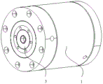
FIG. 1 is a schematic structural view of a first embodiment of a multi-layer drip irrigation pipe co-extrusion compound machine head of the present invention;
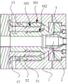
FIG. 2 is a cross-sectional view of a first embodiment of the multi-layer drip irrigation pipe co-extrusion compound head of the present invention;
FIG. 3 is a schematic structural view of a second embodiment of the multi-layer drip irrigation pipe co-extrusion compound machine head of the present invention;
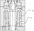
FIG. 4 is a sectional view taken along line A-A of FIG. 3;
FIG. 5 is a sectional view taken along line B-B of FIG. 3;
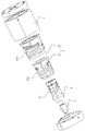
FIG. 6 is an exploded view of the co-extrusion composite head for the multi-layer drip irrigation pipe of FIG. 3;
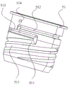
FIG. 7 is one of the schematic structural views of the first sub-outer jacket of FIG. 3;
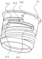
fig. 8 is a second schematic structural diagram of the first sub-outer-sleeve in fig. 3.
Detailed Description
As shown in fig. 1-2, the multilayer drip irrigation pipe co-extrusion composite head of the embodiment comprises: the device comprises a machine shell 1, a mold core 2, a mouth mold 3, an inner sleeve 4 and an outer sleeve 5, wherein the machine shell 1 is provided with a first feed inlet 11 and a second feed inlet 12, an installation channel is formed inside the machine shell 1, the mouth mold 3 is provided with an extrusion opening 31, the mouth mold 3 is arranged at the front end part of the machine shell 1, the outer sleeve 5 is arranged in the installation channel, the inner sleeve 4 is arranged in the outer sleeve 5, and the mold core 2 is arranged in the inner sleeve 4 and inserted into the extrusion opening 31; an extrusion space 100 is formed between the mold core 2 and the extrusion opening 31, a first extrusion channel 101 is formed between the outer sleeve 5 and the inner wall of the installation channel, a second extrusion channel 102 is formed between the inner sleeve 4 and the outer sleeve 5, the first extrusion channel 101 is sleeved outside the second extrusion channel 102, the front end part of the first extrusion channel 101 and the front end part of the second extrusion channel 102 are respectively communicated with the extrusion space 100, the first feed opening 11 is communicated with the first extrusion channel 101, and the second feed opening 12 is communicated with the second extrusion channel 102.
Specifically, in the actual use process of the multilayer drip irrigation pipe co-extrusion compound machine head, the first feeding hole 11 and the second feeding hole 12 are connected with the discharging hole of the extruder, and the material output by the extruder enters the machine shell 1 through the first feeding hole 11 and the second feeding hole 12. The material conveyed by the first feed opening 11 enters the first extrusion channel 101 to form the outermost tube wall, and correspondingly, the material conveyed by the second feed opening 12 enters the second extrusion channel to form the innermost tube wall. The materials extruded and output from the two extrusion channels are jointed together in the extrusion space 100 and finally output from the extrusion port 31 to form the final drip irrigation pipe.
And because the material that is exported from the extruder enters into different channels of extruding through different feed inlets respectively for the material volume in every channel of extruding is less, and then can effectual reduction material pressure. The whole pressure of material is less, and then when exporting from extrusion opening 31 via mold core 2, the corresponding reduction of pressure that mold core 2 received, and then reduces mold core 2 and takes place to be crooked to improve extrusion moulding's drip irrigation pipe's pipe wall uniformity.
As shown in fig. 3 to 8, preferably, in order to further reduce the material pressure, the outer sleeve 5 includes a first sub outer sleeve 51 and a second sub outer sleeve 52, the second sub outer sleeve 52 is disposed in the first sub outer sleeve 51, a first extrusion channel 101 is formed between the first sub outer sleeve 51 and the inner wall of the installation channel, a second extrusion channel 102 is formed between the inner sleeve 4 and the second sub outer sleeve 52, and a third extrusion channel 103 is formed between the first sub outer sleeve 51 and the second sub outer sleeve 52; the housing 1 is provided with a third feed port 13, the front end of the third extrusion channel 103 is communicated with the extrusion space 100, and the third feed port 13 is communicated with the third extrusion channel 103.
Specifically, the jacket 5 has a double jacket structure, in which a first extrusion passage 101 is formed between the first sub-jacket 51 and the casing 1, a second extrusion passage 102 is formed between the second sub-jacket 52 and the inner barrel, and the jacket 5 itself forms a third extrusion passage 103 through the first sub-jacket 51 and the second sub-jacket 52. The pressure of the material extruded by the extruder is further reduced by increasing the number of the extrusion channels, so that the pressure of the material flowing in each extrusion channel in the machine shell 1 is further reduced, and the use reliability of the mold core 2 is ensured.
Wherein, in order to effectively bond three layers of materials output from the extrusion channel together, the front end part of the installation channel is provided with a conical opening 10. Specifically, the first sub-outer sleeve 51 is matched with the tapered opening 10, so that the first extrusion channel 101 outputs materials obliquely towards the mold core 2, and further, the materials output by the first extrusion channel 101 at the outermost layer can be tightly attached to the materials at the inner layer. In addition, the second extrusion channel 102 outputs materials obliquely and reversely to the direction of the mold core 2, so that the materials on the inner side and the outer side are effectively bonded with the material in the middle.
Further, in order to uniformly disperse the material in the extrusion channels to ensure uniform distribution of the material, the thickness of the first extrusion channel 101, the thickness of the second extrusion channel 102 and the thickness of the third extrusion channel 103 are gradually increased along the material flow direction. Specifically, taking the first extrusion channel 101 as an example, the material enters the first extrusion channel 101 through the first feeding hole 11, and the thickness of the feeding end of the first extrusion channel 101 is relatively thick, so that the material is uniformly dispersed along the outer circumference of the first sub-outer sleeve 51, and the material is further uniformly distributed in the circumference direction.
Further, in order to ensure smooth flow of the material and uniform distribution of the material, the outer wall of the first sub outer sleeve 51 is provided with a first spiral groove 511, the outer wall of the inner sleeve 4 is provided with a second spiral groove 41, and the outer wall of the second sub outer sleeve 52 is provided with a third spiral groove 521.
Specifically, taking the first extrusion channel 101 as an example, the material enters the first extrusion channel 101 through the first feeding hole 11, and on the one hand, the material can be dispersed along the circumferential direction, and meanwhile, the dispersed material is gradually conveyed outwards through the first spiral groove 511, so as to ensure that the material can smoothly flow in the first extrusion channel 101. Wherein, along the material flow direction, the depths of the first spiral groove 511, the second spiral groove 41 and the third spiral groove 521 are gradually reduced. Specifically, the material flows in-process under the direction of spiral groove, along with extruding the thickness of passageway and increase gradually for the material spills over from spiral groove gradually and fills extrusion passageway in transportation process, finally realizes exporting complete cartridge type material from extrusion passageway. And the gradual change type structure of the spiral groove enables the extrusion channel to be gradually enlarged, and the pressure of fluid in the space is reduced, so that the reduction of the internal pressure of the machine head is facilitated.
The outer wall of the first sub-outer sleeve 51 at the rear end is tightly attached to the inner wall of the installation channel, and the installation channel covers the partial groove body of the first spiral groove 511 at the rear end; the outer wall of the second sub-outer-sleeve 52 at the rear end is tightly attached to the inner wall of the first sub-outer-sleeve 51, and the first sub-outer-sleeve 51 covers the part of the groove body of the third spiral groove 521 at the rear end; the outer wall of the rear end of the inner sleeve 4 is tightly attached to the inner wall of the second outer sub-sleeve 52, and the second outer sub-sleeve 52 covers the part of the groove body of the second spiral groove 41 at the rear end. Shelter from through the part cell body to spiral groove rear end to make the material enter into and extrude the passageway after, flow in spiral groove that can be quick, and carry along spiral groove forward.
Still further, in order to more effectively improve material distribution uniformity and ensure that the material can smooth and easy flow distribution. First sub-grooves 512 are formed in the outer wall of the first sub-outer-sleeve 51, the first sub-grooves 512 extend along the circumferential direction of the first sub-outer-sleeve 51, first sub-grooves 513 are formed at two ends of the first sub-grooves 512, the first sub-grooves 513 extend along the circumferential direction of the first sub-outer-sleeve 51, and first spiral grooves 511 are connected to two ends of each first sub-groove 513.
Specifically, the material enters the casing 1 through the first inlet 11 and flows into the first diversion groove 512, the rear end portion of the first diversion groove 512 located at the first sub-outer sleeve 51 is covered by the inner wall of the casing 1, and the material flows in the first diversion groove 512 and finally flows to the two end portions. The material will correspondingly flow into the first sub-launders 513 arranged at the corresponding ends of the first launders 512, while the material flows in the first sub-launders 513 towards the two ends, respectively, and finally into the corresponding first spiral grooves 511. Therefore, four first spiral grooves 511 distributed in a spiral winding manner can be arranged on the outer wall of the first sub-outer sleeve 51, on one hand, the requirement of rapid material flow can be met through the plurality of first spiral grooves 511, on the other hand, the materials can be more uniformly distributed along the circumferential direction of the first sub-outer sleeve 51 through the guiding of the plurality of first spiral grooves 511, and the quality of the finally extruded drip irrigation pipe is improved.
Similarly, for the inner sleeve 4, the outer wall of the inner sleeve is provided with a second diversion groove (not labeled) extending along the circumferential direction of the inner sleeve 4, two end portions of the second diversion groove are respectively provided with a second sub-flow groove (not labeled) extending along the circumferential direction of the inner sleeve 4, and two end portions of each second sub-flow groove are respectively connected with a second spiral groove 41. For the functions of the second diversion trench and the second sub-trench disposed on the inner sleeve 4 and the flowing manner of the material therein, reference may be made to the description of the flowing manner of the material in the first outer sub-sleeve 51, which is not limited or described herein.
Similarly, the outer wall of the second outer sub-sleeve 52 is provided with third sub-flow grooves (not marked), the third sub-flow grooves extend along the circumferential direction of the second outer sub-sleeve 52, both ends of the third sub-flow grooves are respectively provided with third sub-flow grooves (not marked), the third sub-flow grooves extend along the circumferential direction of the second outer sub-sleeve 52, and both ends of each third sub-flow groove are respectively connected with a third spiral groove 521. For the functions of the third sub-flow groove and the third sub-flow groove configured on the second sub-outer sleeve 52 and the material flow manner therein, reference may be made to the description of the material flow manner in the first sub-outer sleeve 51, and no limitation or description is made herein.
For the first feed inlets 11, the first diversion grooves 512 are communicated between the first feed inlets 11, so as to facilitate the material entering the corresponding diversion grooves through the three feed inlets. For the third feeding port 13, a first through hole 514 needs to be formed on the first sub-outer sleeve 51, and the third feeding port 13 is communicated with the third diversion groove through the first through hole 514. For the second feed inlet 12, a second through hole 515 needs to be arranged on the first sub-outer casing 51, a third through hole (not labeled) is arranged on the second sub-outer casing 52, the second through hole 515 is communicated with the third through hole, and the second feed inlet 12 is communicated with the second diversion groove through the second through hole 515 and the third through hole in sequence.
Preferably, two first sub-launders 513 are arranged facing away, two second sub-launders are arranged facing away, and two third sub-launders are arranged facing away. Specifically, taking the first extrusion channel 101 as an example, the material enters the first diversion trench 512 through the first feeding hole 11 enough, the material will flow in two ways in the opposite direction, and the material is divided into two even ways at the back position of the first sub-outer-sleeve 51, that is, the material is divided into 4 ways of feeding evenly in the circumferential direction, so as to improve the material distribution uniformity to the maximum.
The utility model provides a pipe co-extrusion composite head is driped irrigation to multilayer has endotheca and overcoat through at the mold core overcoat, and then forms many in the casing and extrude the passageway, and the material of export enters into from the extruder in flowing into the passageway that extrudes that corresponds respectively in the shell, because the material is carried via many extrusion channels, the effectual reduction of material pressure that the extruder extruded, simultaneously, its pressure that receives to the mold core extrudes the material can further reduction to the condition that the mold core takes place to warp appears in the reduction, and then ensure that the position between the extrusion opening of mold core and bush keeps reliable and stable state, finally can extrude the even pipe of driping irrigation of formation wall thickness, with the processingquality who improves the pipe of driping irrigation.
Finally, it should be noted that: the above embodiments are only used to illustrate the technical solution of the present invention, and not to limit it; although the present invention has been described in detail with reference to the foregoing embodiments, it should be understood by those skilled in the art that: the technical solutions described in the foregoing embodiments may still be modified, or some technical features may be equivalently replaced; such modifications and substitutions do not depart from the spirit and scope of the present invention in its corresponding aspects.
Claims (10)
1. The utility model provides a compound aircraft nose is crowded altogether to multilayer drip irrigation pipe which characterized in that includes: the die comprises a machine shell, a die core, a die opening, an inner sleeve and an outer sleeve, wherein a first feed inlet and a second feed inlet are formed in the machine shell, an installation channel is formed in the machine shell, the die opening is provided with an extrusion opening, the die opening is arranged at the front end part of the machine shell, the outer sleeve is arranged in the installation channel, the inner sleeve is arranged in the outer sleeve, and the die core is arranged in the inner sleeve and inserted into the extrusion opening; the die core with extrude and form between the mouth and extrude the space, the overcoat with form first extrusion passageway between the inner wall of installation passageway, the endotheca with form the second between the overcoat and extrude the passageway, first extrusion passageway cover is in the outside that the passageway was extruded to the second, the first front end portion of extruding the passageway with the second is extruded the front end portion of passageway and is communicate respectively extrude the space, first feed inlet with first extrusion passageway intercommunication, the second feed inlet with the passageway intercommunication is extruded to the second.
2. The co-extrusion multiple head for a multi-layer drip irrigation pipe according to claim 1, wherein the outer sleeve comprises a first sub-outer sleeve and a second sub-outer sleeve, the second sub-outer sleeve is disposed in the first sub-outer sleeve, the first extrusion channel is formed between the first sub-outer sleeve and the inner wall of the installation channel, the second extrusion channel is formed between the inner sleeve and the second sub-outer sleeve, and a third extrusion channel is formed between the first sub-outer sleeve and the second sub-outer sleeve; the casing is provided with a third feed port, the front end part of the third extrusion channel is communicated with the extrusion space, and the third feed port is communicated with the third extrusion channel.
3. The co-extrusion multiple head for multi-layer drip irrigation pipe according to claim 2, wherein the front end of the installation channel is provided with a tapered opening.
4. The co-extrusion die for multi-layer drip irrigation pipe as claimed in claim 3, wherein the thickness of the first extrusion channel, the thickness of the second extrusion channel and the thickness of the third extrusion channel are gradually increased along the material flow direction.
5. The co-extrusion multi-layer drip irrigation pipe compounding head according to claim 2, wherein the outer wall of the first sub-outer sleeve is provided with a first spiral groove, the outer wall of the inner sleeve is provided with a second spiral groove, and the outer wall of the second sub-outer sleeve is provided with a third spiral groove.
6. The co-extrusion multiple head for a multilayer drip irrigation pipe according to claim 5, wherein the first spiral groove, the second spiral groove and the third spiral groove have gradually decreasing depths in the material flow direction.
7. The co-extrusion multi-layer drip irrigation pipe compounding head according to claim 6, wherein the outer wall of the first sub-outer sleeve at the rear end is tightly attached to the inner wall of the installation channel, and the installation channel covers a part of the groove body of the first spiral groove at the rear end; the outer wall of the second sub-outer sleeve positioned at the rear end is tightly attached to the inner wall of the first sub-outer sleeve, and the first sub-outer sleeve covers part of the groove body of the third spiral groove positioned at the rear end; the outer wall of the rear end of the inner sleeve is tightly attached to the inner wall of the second sub-outer sleeve, and the second sub-outer sleeve covers the part, located at the rear end, of the second spiral groove.
8. The co-extrusion multi-layer drip irrigation pipe compounding head according to claim 5, wherein the outer wall of the first sub-outer sleeve is provided with a first flow distribution groove extending along the circumferential direction of the first sub-outer sleeve, two end portions of the first flow distribution groove are respectively provided with a first sub-flow groove extending along the circumferential direction of the first sub-outer sleeve, and two end portions of each first sub-flow groove are respectively connected with the first spiral groove;
the outer wall of the inner sleeve is provided with a second diversion groove, the second diversion groove extends along the circumferential direction of the inner sleeve, two end parts of the second diversion groove are respectively provided with a second sub-groove, the second sub-groove extends along the circumferential direction of the inner sleeve, and two end parts of each second sub-groove are respectively connected with the second spiral groove;
the outer wall of the second sub-outer sleeve is provided with a third sub-flow groove, the third sub-flow groove is followed the circumferencial direction of the second sub-outer sleeve extends, the both ends of the third sub-flow groove are provided with the third sub-flow groove respectively, the third sub-flow groove is followed the circumferencial direction of the second sub-outer sleeve extends, every the both ends of the third sub-flow groove are connected with the third spiral groove respectively.
9. The co-extrusion multi-layer drip irrigation pipe compounding head according to claim 8, wherein the first feeding port is communicated with the first diversion groove, the first sub-outer sleeve is provided with a first through hole and a second through hole, the third feeding port is communicated with the third diversion groove through the first through hole, the second sub-outer sleeve is provided with a third through hole, the second through hole is communicated with the third through hole, and the second feeding port is communicated with the second diversion groove through the second through hole and the third through hole in sequence.
10. The co-extrusion multiple head for a multilayer drip irrigation pipe according to claim 8, wherein the two first sub-gutters are arranged in a back-to-back manner, the two second sub-gutters are arranged in a back-to-back manner, and the two third sub-gutters are arranged in a back-to-back manner.
Priority Applications (1)
| Application Number | Priority Date | Filing Date | Title |
|---|---|---|---|
| CN202023104335.8U CN214926885U (en) | 2020-12-22 | 2020-12-22 | Multi-layer drip irrigation pipe co-extrusion composite machine head |
Applications Claiming Priority (1)
| Application Number | Priority Date | Filing Date | Title |
|---|---|---|---|
| CN202023104335.8U CN214926885U (en) | 2020-12-22 | 2020-12-22 | Multi-layer drip irrigation pipe co-extrusion composite machine head |
Publications (1)
| Publication Number | Publication Date |
|---|---|
| CN214926885U true CN214926885U (en) | 2021-11-30 |
Family
ID=79113645
Family Applications (1)
| Application Number | Title | Priority Date | Filing Date |
|---|---|---|---|
| CN202023104335.8U Active CN214926885U (en) | 2020-12-22 | 2020-12-22 | Multi-layer drip irrigation pipe co-extrusion composite machine head |
Country Status (1)
| Country | Link |
|---|---|
| CN (1) | CN214926885U (en) |
-
2020
- 2020-12-22 CN CN202023104335.8U patent/CN214926885U/en active Active
Similar Documents
| Publication | Publication Date | Title |
|---|---|---|
| CN1492802A (en) | Tubular multilayer films, method and apparatus for preparing the same | |
| CN105037881A (en) | Composite plastic tube | |
| GB2072084A (en) | Extruder head for extruding an interior lining and an exterior coating layer of materials onto a tubular permeable reinforcement | |
| CN108544732B (en) | Double-wall corrugated pipe with reinforced coating and manufacturing mold thereof | |
| CN112590168A (en) | Multilayer drip irrigation pipe co-extrusion composite extrusion equipment | |
| CN214926885U (en) | Multi-layer drip irrigation pipe co-extrusion composite machine head | |
| KR101512342B1 (en) | Manufacturing apparatus of pipe for communications line | |
| CN211542302U (en) | Extrusion die with cooling sleeve for plastic extruder | |
| CN107351346B (en) | Combined die for plastic extruder | |
| CN214294369U (en) | Simple and easy cable is extruded and is annotated mould subassembly, cable extruder head and cable extruder of color strip | |
| WO2023103108A1 (en) | Forming device for continuous fiber reinforced composite pipe | |
| CN107336418A (en) | Assembling die for plastic extruder | |
| CN210552874U (en) | Multi-layer machine head of corrugating machine | |
| CN214137232U (en) | AAB three-layer co-extrusion die head of film blowing machine | |
| CN205343739U (en) | Clad steel fiber tube mould | |
| CN2393707Y (en) | Multi-layer squeezing die | |
| CN213891192U (en) | Solid-wall co-extrusion pipe mould with functional layer | |
| CN217047419U (en) | Inner and outer pipe co-extrusion die | |
| CN207256825U (en) | A kind of runner assembly for coating extrusion die and cladding extrusion die | |
| CN206085590U (en) | Processingequipment is extruded to PE pipe vitta | |
| CN207059182U (en) | Spreader for guide's distributor of plastic extruder | |
| CN216506626U (en) | Co-extrusion die | |
| CN218876220U (en) | Co-extrusion die for special-shaped pipe structural wall pipe | |
| CN216683249U (en) | Double-layer co-extrusion die for multi-cavity pipe | |
| CN218803892U (en) | Double-wall corrugated pipe extrusion die |
Legal Events
| Date | Code | Title | Description |
|---|---|---|---|
| GR01 | Patent grant | ||
| GR01 | Patent grant |