CN214844481U - Welding rod strength detection tool - Google Patents
Welding rod strength detection tool Download PDFInfo
- Publication number
- CN214844481U CN214844481U CN202121566211.3U CN202121566211U CN214844481U CN 214844481 U CN214844481 U CN 214844481U CN 202121566211 U CN202121566211 U CN 202121566211U CN 214844481 U CN214844481 U CN 214844481U
- Authority
- CN
- China
- Prior art keywords
- positioning
- welding rod
- rod
- pressing
- frame
- Prior art date
- Legal status (The legal status is an assumption and is not a legal conclusion. Google has not performed a legal analysis and makes no representation as to the accuracy of the status listed.)
- Active
Links
Images


Abstract
The utility model provides a welding rod strength detection tool, which comprises a clamping and positioning assembly, wherein both ends of a welding rod to be tested are arranged on corresponding clamping and positioning mechanisms during testing; the pressing equipment is arranged above the welding rod to be detected and used for providing downward pressure for the welding rod to be detected, and comprises a pressing rod, and a pressure sensor for detecting a current pressure signal is arranged on the pressing rod. Welding rod strength detection frock press from both sides tight location back at the welding rod, utilize and push down the compressive strength that equipment measured the welding rod, by operating personnel according to the crooked condition of welding rod and the pressure data of pressure sensor feedback this moment, judge the compressive property of welding rod.
Description
Technical Field
The utility model belongs to the technical field of the welding rod detects, especially, relate to a welding rod intensity detects frock.
Background
The welding rod is a metal strip which is melted and filled in a joint of welding workpieces during gas welding or electric welding.
The welding rod includes the core wire and paints the coating in the core wire outside, and one of them important index of crossbeam welding rod quality is the intensity of welding rod, seldom has the frock that detects to the intensity of welding rod specially on the present market, relies on artificial experience mostly, and the intensity of the electrode is judged out to unable accuracy like this, and the error is great.
Disclosure of Invention
In view of this, the utility model aims at providing a welding rod intensity detects frock to solve and lack the frock that the intensity that is directed against the welding rod specially at present, rely on artificial experience to judge, there is the great problem of error.
In order to achieve the above purpose, the technical scheme of the utility model is realized like this:
the utility model provides a welding rod intensity detects frock, includes:
a clamping and positioning assembly comprising two clamping and positioning structures respectively arranged at two ends of the welding rod to be tested, wherein the two ends of the welding rod to be tested are arranged on the corresponding clamping and positioning structures during testing; the clamping and positioning mechanisms are slidably arranged on the frame body, and each clamping and positioning mechanism is provided with a jacking piece for jacking the welding rod;
a pressing device arranged above the welding rod to be detected and used for providing downward pressure for the welding rod to be detected, wherein the pressing device comprises a pressing rod, and a pressure sensor for detecting a current pressure signal is arranged on the pressing rod;
the frame body, the clamping and positioning assembly and the hold-down device are all mounted on the frame body.
Furthermore, the clamping and positioning structure comprises a positioning block and a tightening rod matched with the positioning block;
the welding rod positioning device comprises a positioning block, a welding rod to be detected and a welding rod to be detected, wherein the positioning block is a steel block, one side of the upper surface of the steel block is provided with an arc-shaped groove for placing the end part of the welding rod to be detected, the other side of the upper surface of the steel block extends upwards to form a connecting part, and the connecting part is arranged at the end part of the arc-shaped groove;
the tightening rod is a screw rod, an internal thread hole corresponding to the tightening rod is formed in the connecting part, one end of the tightening rod penetrates through the internal thread hole and then is arranged in the arc-shaped groove, and a knob is arranged at the other end of the tightening rod;
the outer diameter of the tightening rod corresponds to the diameter of the arc-shaped groove.
Furthermore, press from both sides tight location structure and still include the U template, the locating piece slidable sets up in the U template inboard, open the side of locating piece has the through-hole, open the side of U template has the locating hole that corresponds with the through-hole, the locating hole corresponds and is equipped with positioning bolt, the locating piece passes through positioning bolt with the U template and fixes.
Furthermore, two through holes are formed in the side surface of the positioning block and are respectively arranged at the front end and the rear end of the side surface;
a plurality of positioning holes are transversely formed in the U-shaped plate, and the positions of the positioning blocks are adjusted through the positioning holes of different positioning holes.
Further, the frame body comprises a bottom frame, a middle frame and a top frame which are arranged from bottom to top in sequence, and adjacent frames are fixedly connected through supporting columns;
the clamping and positioning assembly is arranged on the middle frame;
the hold-down device is mounted on the top frame.
Furthermore, the bottom frame is an H-shaped frame, bolt holes are formed in the H-shaped frame, and the H-shaped frame is fixed to the ground through expansion bolts or foundation bolts.
Furthermore, a collecting device is also arranged on the supporting column between the bottom frame and the middle frame;
the collecting device comprises a collecting funnel and a square ring which is fixed on the side surface of the collecting funnel and is matched with the supporting column, and the square ring is fixed with the supporting column through a bolt;
a discharge pipe is arranged at the bottom of the collecting funnel;
the collecting funnel is arranged right below the pressing equipment.
Furthermore, the top frame comprises two beams fixedly arranged at the tops of the support columns, the outer side of the side of each beam is sleeved with a square steel sleeve, a connecting plate is arranged between the two square steel sleeves, and the pressing equipment is arranged below the connecting plate;
the square steel sleeve is provided with bolt holes, the cross beam is provided with a plurality of adjusting holes corresponding to the bolt holes, and the square steel sleeve is fixedly connected with the cross beam through bolts.
Furthermore, the pressing equipment is one of a hydraulic cylinder, an air cylinder and an electric cylinder
A pressing block is arranged at the bottom of a pressing rod of the pressing equipment, the bottom of the pressing block is an arc-shaped surface, and an arc-shaped groove corresponding to the welding rod to be detected is formed in the middle of the arc-shaped surface;
the pressure sensor is arranged between the lower pressure rod and the pressing block.
Compared with the prior art, welding rod strength detection frock have following advantage:
(1) welding rod strength detection frock clamp the location back to the welding rod, utilize and push down the compressive strength that equipment measured the welding rod, by operating personnel according to the crooked condition of welding rod and the pressure data of pressure sensor feedback this moment, judge the compressive property of welding rod.
(2) When the welding rod strength detection tool is used for testing, two ends of a welding rod to be tested are placed in the arc-shaped groove, and then the tightening rods at one end or two ends are rotated to tightly and fixedly tighten the welding rod, so that the welding rod is prevented from axially moving in the testing process; the position of the positioning block can be adjusted through the positioning hole, so that the position of the clamped welding rod is adjusted, the middle position of the welding rod is located under the pressing device, and the test result is more accurate.
(3) The welding rod strength detection tool is provided with the collecting funnel, and the falling coating can be collected through the collecting funnel; the bottom of collecting the funnel is equipped with row material pipe, arranges the purpose of material pipe and discharges the coating of collecting, through the weight of the coating of collecting, also can judge the coagulation property of coating and core wire, is an important index of evaluation welding rod intensity.
Drawings
The accompanying drawings, which form a part hereof, are included to provide a further understanding of the invention, and are incorporated in and constitute a part of this specification, illustrate embodiments of the invention and together with the description serve to explain the invention without undue limitation. In the drawings:
FIG. 1 is an overall structure diagram of a welding rod strength detection tool according to an embodiment of the present invention;
fig. 2 is a structural diagram of a clamping and positioning structure according to an embodiment of the present invention;
fig. 3 is a diagram of a positioning block according to an embodiment of the present invention;
fig. 4 is a block structure diagram according to an embodiment of the present invention.
Description of reference numerals:
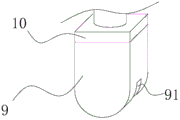
1. clamping and positioning the structure; 11. a U-shaped plate; 111. positioning holes; 12. positioning blocks; 121. an arc-shaped groove; 122. a tightening rod; 123. a connecting portion; 124. a knob; 2. pressing equipment; 3. a bottom frame; 4. a middle frame; 5. a cross beam; 6. a collection funnel; 61. a square ring; 62. a discharge pipe; 7. a connecting plate; 8. a square steel sleeve; 9. briquetting; 91. an arc-shaped slot; 10. a pressure sensor.
Detailed Description
It should be noted that, in the present invention, the embodiments and features of the embodiments may be combined with each other without conflict.
In the description of the present invention, it is to be understood that the terms "center", "longitudinal", "lateral", "up", "down", "front", "back", "left", "right", "vertical", "horizontal", "top", "bottom", "inner", "outer", and the like, indicate orientations or positional relationships based on the orientations or positional relationships shown in the drawings, and are used merely for convenience of description and for simplicity of description, and do not indicate or imply that the device or element being referred to must have a particular orientation, be constructed and operated in a particular orientation, and therefore, should not be construed as limiting the present invention. Furthermore, the terms "first", "second", etc. are used for descriptive purposes only and are not to be construed as indicating or implying relative importance or implicitly indicating the number of technical features indicated. Thus, a feature defined as "first," "second," etc. may explicitly or implicitly include one or more of that feature. In the description of the present invention, "a plurality" means two or more unless otherwise specified.
In the description of the present invention, it is to be noted that, unless otherwise explicitly specified or limited, the terms "mounted," "connected," and "connected" are to be construed broadly, and may be, for example, fixedly connected, detachably connected, or integrally connected; can be mechanically or electrically connected; they may be connected directly or indirectly through intervening media, or they may be interconnected between two elements. The specific meaning of the above terms in the present invention can be understood by those of ordinary skill in the art through specific situations.
The present invention will be described in detail below with reference to the accompanying drawings in conjunction with embodiments.
As shown in FIG. 1, a welding rod strength detection tool comprises: the clamping and positioning assembly comprises two clamping and positioning structures which are respectively arranged at two ends of the welding rod to be tested, and the two ends of the welding rod to be tested are arranged on the corresponding clamping and positioning mechanisms during testing; the clamping and positioning mechanisms are slidably arranged on the frame body, and each clamping and positioning mechanism is provided with a jacking piece for jacking the welding rod;
the pressing device is arranged above the welding rod to be detected and used for providing downward pressure for the welding rod to be detected, the pressing device comprises a pressing rod, a pressure sensor for detecting a current pressure signal is arranged on the pressing rod, the pressure sensor is connected with an upper computer, and the pressure resistance of the welding rod is judged by an operator according to the bending condition of the welding rod and pressure data fed back by the pressure sensor at the moment, wherein the pressure sensor and the upper computer are both in the prior art, and detailed description is omitted here;
wherein, press from both sides tight locating component and push down equipment and all install on this support body.
After the welding rod can be clamped and positioned, the compressive strength of the welding rod is measured by utilizing the pressing equipment, and the compressive property of the welding rod is judged by an operator according to the bending condition of the welding rod and the pressure data fed back by the pressure sensor at the moment.
As shown in fig. 1 to 3, the clamping and positioning structure includes a positioning block and a tightening rod disposed in cooperation with the positioning block;
the welding rod positioning device comprises a positioning block, a welding rod to be detected and a welding rod to be detected, wherein the positioning block is a steel block, one side of the upper surface of the steel block is provided with an arc-shaped groove for placing the end part of the welding rod to be detected, the other side of the upper surface of the steel block extends upwards to form a connecting part, and the connecting part is arranged at the end part of the arc-shaped groove;
the tightening rod is a screw rod, an internal thread hole corresponding to the tightening rod is formed in the connecting part, one end of the tightening rod penetrates through the internal thread hole and then is arranged in the arc-shaped groove, and a knob is arranged at the other end of the tightening rod;
the outer diameter of the tightening rod corresponds to the diameter of the arc-shaped groove.
The both ends of the welding rod that awaits measuring are placed in the arc recess, then the tight pole in top of rotatory one end or both ends, and it is fixed to push up the welding rod, prevents axial displacement among the test procedure.
The clamping and positioning structure further comprises a U-shaped plate, the positioning block is slidably arranged on the inner side of the U-shaped plate, a through hole is formed in the side face of the positioning block, a positioning hole corresponding to the through hole is formed in the side face of the U-shaped plate, a positioning bolt is correspondingly arranged in the positioning hole, and the positioning block is fixed with the U-shaped plate through the positioning bolt.
The side surface of the positioning block is provided with two through holes which are respectively arranged at the front end and the rear end of the side surface;
a plurality of positioning holes are transversely formed in the U-shaped plate, and the positions of the positioning blocks are adjusted through the positioning holes of different positioning holes. The position of the positioning block can be adjusted through the positioning hole, so that the position of the clamped welding rod is adjusted, the middle position of the welding rod is located under the pressing device, and the test result is more accurate.
The frame body comprises a bottom frame, a middle frame and a top frame which are arranged from bottom to top in sequence, and adjacent frames are fixedly connected through supporting columns; the clamping and positioning assembly is arranged on the middle frame; the hold-down device is mounted on the top frame.
The bottom frame is an H-shaped frame, bolt holes are formed in the H-shaped frame, the H-shaped frame is fixed to the ground through expansion bolts or foundation bolts, and the frame body does not need to be fixed or not fixed according to the judgment of specific conditions. The user also can increase the wheel in the bottom of support body to realize the purpose of convenient removal.
A collecting device is also arranged on the supporting column between the bottom frame and the middle frame;
the collecting device comprises a collecting funnel and a square ring which is fixed on the side surface of the collecting funnel and is matched with the supporting column, and the square ring is fixed with the supporting column through a bolt; the utility model provides a support body entire body adopts the square steel, for convenient fixed collection funnel, is convenient for will collect the funnel and fix with the support column in the side welding side ring of collecting the funnel.
The collecting funnel is arranged right below the pressing equipment.
Because the welding rod can appear the condition that "collapses porcelain" in crooked in-process, can collect the coating that drops through collecting the funnel.
The bottom of collecting the funnel is equipped with row material pipe, arranges the purpose of material pipe and discharges the coating of collecting, through the weight of the coating of collecting, also can judge the coagulation property of coating and core wire, is an important index of evaluation welding rod intensity.
The top frame comprises two beams fixedly arranged at the tops of the supporting columns, the outer side of the side of each beam is sleeved with a square steel sleeve, a connecting plate is arranged between the two square steel sleeves, and the pressing equipment is arranged below the connecting plate;
the square steel sleeve is provided with bolt holes, the cross beam is provided with a plurality of adjusting holes corresponding to the bolt holes, the square steel sleeve is fixedly connected with the cross beam through bolts, and the position of the pressing equipment can be conveniently adjusted through the square steel sleeve. When the device is used for testing, the position of the pressing equipment is not adjusted under the general condition, but the position of the welding rod is adjusted through the positioning block.
The pressing equipment is one of a hydraulic cylinder, an air cylinder and an electric cylinder
As shown in fig. 1 and 3, a pressing block is arranged at the bottom of a lower pressing rod of the lower pressing device, the bottom of the pressing block is an arc-shaped surface, and an arc-shaped groove corresponding to the welding rod to be detected is formed in the middle of the arc-shaped surface; the arc-shaped groove is used for limiting the welding rod to be tested, and the welding rod is prevented from rolling away from the pressing block in the testing process.
The pressure sensor is arranged between the lower pressure rod and the pressing block.
The above description is only a preferred embodiment of the present invention, and should not be taken as limiting the invention, and any modifications, equivalent replacements, improvements, etc. made within the spirit and principle of the present invention should be included in the protection scope of the present invention.
Claims (9)
1. Welding rod strength detection frock, its characterized in that includes:
a clamping and positioning assembly comprising two clamping and positioning structures respectively arranged at two ends of the welding rod to be tested, wherein the two ends of the welding rod to be tested are arranged on the corresponding clamping and positioning structures during testing; the clamping and positioning mechanisms are slidably arranged on the frame body, and each clamping and positioning mechanism is provided with a jacking piece for jacking the welding rod;
a pressing device arranged above the welding rod to be detected and used for providing downward pressure for the welding rod to be detected, wherein the pressing device comprises a pressing rod, and a pressure sensor for detecting a current pressure signal is arranged on the pressing rod;
the frame body, the clamping and positioning assembly and the hold-down device are all mounted on the frame body.
2. The electrode strength detection tool according to claim 1, characterized in that: the clamping and positioning structure comprises a positioning block and a tightening rod matched with the positioning block;
the welding rod positioning device comprises a positioning block, a welding rod to be detected and a welding rod to be detected, wherein the positioning block is a steel block, one side of the upper surface of the steel block is provided with an arc-shaped groove for placing the end part of the welding rod to be detected, the other side of the upper surface of the steel block extends upwards to form a connecting part, and the connecting part is arranged at the end part of the arc-shaped groove;
the tightening rod is a screw rod, an internal thread hole corresponding to the tightening rod is formed in the connecting part, one end of the tightening rod penetrates through the internal thread hole and then is arranged in the arc-shaped groove, and a knob is arranged at the other end of the tightening rod;
the outer diameter of the tightening rod corresponds to the diameter of the arc-shaped groove.
3. The electrode strength detection tool according to claim 2, characterized in that: the clamping and positioning structure further comprises a U-shaped plate, the positioning block is slidably arranged on the inner side of the U-shaped plate, a through hole is formed in the side face of the positioning block, a positioning hole corresponding to the through hole is formed in the side face of the U-shaped plate, a positioning bolt is correspondingly arranged in the positioning hole, and the positioning block is fixed with the U-shaped plate through the positioning bolt.
4. The electrode strength detection tool according to claim 3, characterized in that: the side surface of the positioning block is provided with two through holes which are respectively arranged at the front end and the rear end of the side surface;
a plurality of positioning holes are transversely formed in the U-shaped plate, and the positions of the positioning blocks are adjusted through the positioning holes of different positioning holes.
5. The electrode strength detection tool according to claim 3, characterized in that: the frame body comprises a bottom frame, a middle frame and a top frame which are arranged from bottom to top in sequence, and adjacent frames are fixedly connected through supporting columns;
the clamping and positioning assembly is arranged on the middle frame;
the hold-down device is mounted on the top frame.
6. The electrode strength detection tool according to claim 5, characterized in that: the bottom frame is an H-shaped frame, bolt holes are formed in the H-shaped frame, and the H-shaped frame is fixed with the ground through expansion bolts or foundation bolts.
7. The electrode strength detection tool according to claim 5, characterized in that: a collecting device is also arranged on the supporting column between the bottom frame and the middle frame;
the collecting device comprises a collecting funnel and a square ring which is fixed on the side surface of the collecting funnel and is matched with the supporting column, and the square ring is fixed with the supporting column through a bolt;
a discharge pipe is arranged at the bottom of the collecting funnel;
the collecting funnel is arranged right below the pressing equipment.
8. The electrode strength detection tool according to claim 5, characterized in that: the top frame comprises two beams fixedly arranged at the tops of the supporting columns, the outer side of the side of each beam is sleeved with a square steel sleeve, a connecting plate is arranged between the two square steel sleeves, and the pressing equipment is arranged below the connecting plate;
the square steel sleeve is provided with bolt holes, the cross beam is provided with a plurality of adjusting holes corresponding to the bolt holes, and the square steel sleeve is fixedly connected with the cross beam through bolts.
9. The electrode strength detection tool according to claim 1 or 8, characterized in that: the pressing equipment is one of a hydraulic cylinder, an air cylinder and an electric cylinder
A pressing block is arranged at the bottom of a pressing rod of the pressing equipment, the bottom of the pressing block is an arc-shaped surface, and an arc-shaped groove corresponding to the welding rod to be detected is formed in the middle of the arc-shaped surface;
the pressure sensor is arranged between the lower pressure rod and the pressing block.
Priority Applications (1)
| Application Number | Priority Date | Filing Date | Title |
|---|---|---|---|
| CN202121566211.3U CN214844481U (en) | 2021-07-09 | 2021-07-09 | Welding rod strength detection tool |
Applications Claiming Priority (1)
| Application Number | Priority Date | Filing Date | Title |
|---|---|---|---|
| CN202121566211.3U CN214844481U (en) | 2021-07-09 | 2021-07-09 | Welding rod strength detection tool |
Publications (1)
| Publication Number | Publication Date |
|---|---|
| CN214844481U true CN214844481U (en) | 2021-11-23 |
Family
ID=78813916
Family Applications (1)
| Application Number | Title | Priority Date | Filing Date |
|---|---|---|---|
| CN202121566211.3U Active CN214844481U (en) | 2021-07-09 | 2021-07-09 | Welding rod strength detection tool |
Country Status (1)
| Country | Link |
|---|---|
| CN (1) | CN214844481U (en) |
-
2021
- 2021-07-09 CN CN202121566211.3U patent/CN214844481U/en active Active
Similar Documents
| Publication | Publication Date | Title |
|---|---|---|
| CN205981086U (en) | Utensil is examined to high accuracy screw rod measurement over pins | |
| CN210639007U (en) | Hardness detection device for steel pipe | |
| CN109855956B (en) | Device for detecting tensile property of wide strips of geosynthetics and measuring method thereof | |
| CN111781071B (en) | Bending test device for reinforcing steel bars | |
| CN213903163U (en) | Socket joint type disc buckle type steel pipe support component strength testing device | |
| CN211717342U (en) | Tool checking fixture error and leakage prevention device | |
| CN106695097B (en) | A kind of end plate welding equipment of nuclear fuel cluster | |
| CN205175840U (en) | Multiplexer utensil bending test machine | |
| CN214844481U (en) | Welding rod strength detection tool | |
| CN212432834U (en) | Anti testing machine that rolls over of cement with limit function | |
| CN110646295B (en) | Anti bearing capacity detection device that splits of detachable RPC apron | |
| CN218331013U (en) | Pressure resistance detection device suitable for metal display board frame body | |
| CN105823690A (en) | Bending tester for of tools and utensils | |
| CN212059668U (en) | Brinell hardness indentation diameter measurement auxiliary fixtures | |
| CN115031670A (en) | Target hole site detection device and detection method thereof | |
| CN206557013U (en) | A kind of metal-material extension rate test detects positioner | |
| CN210374937U (en) | Hole center distance measuring device | |
| CN209978807U (en) | Tool for clamping differential transformer type displacement sensor | |
| CN207036763U (en) | A kind of calibrating tube supporting structure for nuclear power plant's heat exchanger tube interior crossing type EDDY CURRENT | |
| CN215003401U (en) | Welding rod size detection device | |
| CN214620917U (en) | Detection tool for automobile instrument panel front wall connecting plate assembly | |
| CN220507913U (en) | Hole detection tool | |
| CN217845141U (en) | Insulator square hole detection device | |
| CN217688189U (en) | Pipe marking auxiliary device | |
| CN114166085B (en) | Beam tube welding assembly gauge |
Legal Events
| Date | Code | Title | Description |
|---|---|---|---|
| GR01 | Patent grant | ||
| GR01 | Patent grant |