CN214837216U - Gas compressor and handheld dust collector - Google Patents
Gas compressor and handheld dust collector Download PDFInfo
- Publication number
- CN214837216U CN214837216U CN202120544085.5U CN202120544085U CN214837216U CN 214837216 U CN214837216 U CN 214837216U CN 202120544085 U CN202120544085 U CN 202120544085U CN 214837216 U CN214837216 U CN 214837216U
- Authority
- CN
- China
- Prior art keywords
- blade
- stage
- unit
- moving
- stationary blade
- Prior art date
- Legal status (The legal status is an assumption and is not a legal conclusion. Google has not performed a legal analysis and makes no representation as to the accuracy of the status listed.)
- Expired - Fee Related
Links
Images


Landscapes
- Structures Of Non-Positive Displacement Pumps (AREA)
Abstract
The utility model provides a compressor, including casing, power module and at least two-stage sound leaf unit, the sound leaf unit coaxial arrangement of each grade, every grade sound leaf unit includes a movable blade and a quiet leaf, movable blade and quiet leaf coaxial arrangement and clearance fit, movable blade, quiet leaf clearance fit in proper order between the sound leaf unit of adjacent grade, movable blade and power module transmission are connected, sound leaf unit and power module all set up inside the casing; a handheld dust collector comprising the air compressor is also provided. The utility model discloses with the coaxial arrangement of at least two-stage movable and static blade unit, be the series connection form, movable blade, the quiet leaf of each grade between the movable and static leaf unit clearance fit in proper order, and each grade movable blade is driven by the power pack who corresponds with it, and it is big to have the amount of wind, and the motor external diameter is little, and is small, and the operation rotational speed is low, and the operation wind is made an uproar low, has widened the high-efficient region of dust catcher work, characteristics that work efficiency is high.
Description
Technical Field
The utility model belongs to the technical field of domestic appliance, especially, relate to a compressor and hand-held type dust catcher.
Background
The vacuum cleaner can be divided into a vertical type, a horizontal type and a handheld type according to the structure. The working principle of the dust collector is that the blades are driven by the motor to rotate at a high speed, air negative pressure is generated in the sealed shell, and dust is sucked. And along with the increasing demands of people in life, the air power of the dust collector is required to be higher and higher.
In the process of pursuing larger air volume and larger suction force, the conventional small household handheld dust collector usually needs to be realized by increasing the diameter of the impeller or increasing the rotating speed of the impeller to maximize the air power, so that the requirement on the strength of the impeller material is higher, the material cost is increased, the diameter and the volume of the fan are increased, relatively generated wind noise is also larger, the small household handheld dust collector is not suitable for being held by a hand to operate, additionally, along with the increase of the suction air volume, the vacuum degree of the dust collector is obviously reduced, and a working high-efficiency area is narrower.
SUMMERY OF THE UTILITY MODEL
An object of the utility model is to overcome the not enough of above-mentioned prior art existence, provide a compressor and hand-held type dust catcher, solved among the prior art for improving air power, the increase volume of induced drafting, the narrow problem in fan diameter and the volume increase, wind noise height, the high-efficient district of fan work that leads to.
In a first aspect, the utility model provides a compressor, including casing, power module and at least two-stage sound leaf unit, sound leaf unit coaxial the arranging at all levels, every grade sound leaf unit includes a movable blade and a quiet leaf, movable blade and quiet leaf coaxial arrangement and clearance fit, movable blade, quiet leaf are clearance fit in proper order between the adjacent sound leaf unit at all levels, the movable blade is connected with the power module transmission, sound leaf unit and power module all set up inside the casing.
In some embodiments, the power module comprises power units with the number of stages the same as that of the moving blade units, the power units comprise motors and driving modules, the power units correspond to the moving blade units one to one, the motors are in transmission connection with the moving blades, the driving modules are in signal connection with the motors, and the driving modules are connected to the outer wall surface of the shell.
In some embodiments, the air guide blade is connected to the inner wall surface of the casing, the air guide blade is arranged at the front end of the first-stage moving and stationary blade unit, the air guide blade is in clearance fit with the moving blade of the first-stage moving and stationary blade unit, and the first-stage moving and stationary blade unit is the moving and stationary blade unit at the most front end in the airflow direction.
In some embodiments, a heat dissipation plane is disposed on an outer wall surface of the housing, and the driving module includes a heating element, and the heating element is tightly attached to the heat dissipation plane.
In some embodiments, the driving modules of the power units are commonly disposed on the same driving substrate, and the driving substrate is connected to an external power source.
In some embodiments, the driving module further includes a driving IC and a pressure sensor, the pressure sensor is used for detecting the wind pressure in the movable and stationary blade units corresponding to the driving module to which the pressure sensor belongs, the casing is provided with pressure measuring through holes at positions corresponding to the movable and stationary blade units, the pressure sensor is connected to the corresponding pressure measuring through holes, and the pressure sensor is in signal connection with the driving IC.
In some embodiments, the rotation directions of the movable blades of the adjacent movable and static blade units are opposite.
In some embodiments, the device comprises two stages of moving and static blade units, namely a first stage moving and static blade unit and a second stage moving and static blade unit, the wind guide blades, the first-stage movable and fixed blade units and the second-stage movable and fixed blade units are sequentially arranged along the airflow direction, the shell comprises a first shell, a second shell and a connecting shell, the first stage moving and static blade unit comprises a first stage moving blade and a first stage static blade, the second-stage moving and static blade unit comprises a second-stage moving blade and a second-stage static blade, the air guide blade is connected with the inner wall surface of the first shell, the first stage stationary blade is connected to an inner wall surface of the connecting casing, the second stage stationary blade is connected to an inner wall surface of the second casing, the power module comprises a first power unit and a second power unit, a motor of the first power unit is arranged at the front end of the air guide blade, and a motor of the second power unit is arranged at the rear end of the second stage stationary blade.
In some embodiments, the first stage blades and the second stage blades have an equal outer diameter, and the guide blades, the first stage vanes, and the second stage vanes have an equal outer diameter.
In a second aspect, the present invention further provides a handheld vacuum cleaner comprising a compressor as described in any of the previous embodiments.
The utility model has the advantages that:
therefore, according to the embodiment of the disclosure, at least two stages of moving and static blade units are coaxially arranged and are in a series connection mode, moving blades and static blades between the moving and static blade units at all stages are in clearance fit in sequence, and each stage of moving blades is driven by the power unit corresponding to the moving blades.
Drawings
The present invention is further explained by using the drawings, but the embodiments in the drawings do not constitute any limitation to the present invention, and for those skilled in the art, other drawings can be obtained according to the following drawings without any inventive work.
Fig. 1 is a schematic diagram of the overall structure of a compressor disclosed in the present invention.
Fig. 2 is a schematic view of a cross-section internal structure of a compressor disclosed in the present invention.
Fig. 3 is a schematic structural diagram of a driving module in a compressor according to the present invention.
Fig. 4 is a schematic diagram of a compressor at a certain oblique elevation angle.
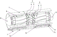
Fig. 5 is a schematic cross-sectional internal structure diagram of an axial compressor in the embodiment 1.
Fig. 6 is a schematic structural diagram of the matching of each stage of moving and stationary blade units in the mixed-flow compressor in the embodiment 2.
Detailed Description
The technical solution of the present invention will be described clearly and completely with reference to the accompanying drawings, and obviously, the described embodiments are some, but not all embodiments of the present invention. Based on the embodiments in the present invention, all other embodiments obtained by a person skilled in the art without creative work belong to the protection scope of the present invention.
In the description of the present invention, it should be noted that the terms "center", "upper", "lower", "left", "right", "vertical", "horizontal", "inner", "outer", and the like indicate orientations or positional relationships based on the orientations or positional relationships shown in the drawings, and are only for convenience of description and simplification of description, but do not indicate or imply that the device or element referred to must have a specific orientation, be constructed and operated in a specific orientation, and thus, should not be construed as limiting the present invention. Furthermore, the terms "first," "second," and "third" are used for descriptive purposes only and are not to be construed as indicating or implying relative importance.
In the description of the present invention, when it is described that a specific device is located between a first device and a second device, an intervening device may or may not be present between the specific device and the first device or the second device. When a particular device is described as being coupled to other devices, that particular device may be directly coupled to the other devices without intervening devices or may be directly coupled to the other devices with intervening devices.
Techniques, methods, and apparatus known to those of ordinary skill in the relevant art may not be discussed in detail but are intended to be part of the specification where appropriate.
The applicant researches and discovers that:
the existing small household handheld dust collector has the advantages that the aerodynamic part is mostly a centrifugal or mixed-flow impeller, and for obtaining larger air power, the large impeller diameter or the impeller rotating speed is often needed to be increased, so that the requirement on the strength of the impeller material is higher, the material cost is increased, the diameter and the volume of a fan are increased, relatively generated wind noise is also larger, the small household handheld dust collector is not suitable for being held by a hand to operate, additionally, along with the increase of the suction air volume, the vacuum degree of the dust collector is obviously reduced, and the working high-efficiency area is narrower.
In view of the above, referring to fig. 1 to 4, in a first aspect of the present disclosure, there is provided a compressor for a handheld vacuum cleaner, the compressor includes a housing 1, a power module 2 and at least two stages of moving and stationary blade units 3, each stage of moving and stationary blade unit 3 is coaxially arranged and is in a series connection form, each stage of moving and stationary blade unit 3 includes a moving blade 4 and a stationary blade 5, the moving blade 4 and the stationary blade 5 are coaxially arranged and are in clearance fit, the moving blade 4 and the stationary blade 5 are sequentially in clearance fit between adjacent stages of moving and stationary blade units 3, the moving blade 4 is in transmission connection with the power module 2, the moving blade unit 3 and the power module 2 are both disposed inside the housing 1, the housing 1 is in a hollow cylindrical structure, the moving and stationary blade units 3 are all in clearance fit inside the housing 1, and a specific airflow direction is formed along the housing 1 under the driving of the power module 2.
In the airflow direction, the moving blade 4 and the stationary blade 5 of the moving blade unit 3 at the leading end, and the moving blade 4 and the stationary blade 5 of the moving blade unit 3 at the trailing end are arranged in this order; of course, the stator blade 5 and the rotor blade 4 of the leading stator blade unit 3 may be followed by the stator blade 5 and the rotor blade 4 of the trailing stator blade unit 3.
Compared with a centrifugal impeller, the axial-flow impeller with the same outer diameter and rotating speed has the advantage of large air volume, and under the requirement of the same air volume, the outer diameter and the working operation rotating speed of the motor 6 are effectively reduced, and the wind noise is also lower. In addition, by adopting the mode that the movable blades 5 and the static blades 5 are arranged in series at two stages or more than two stages, each stage of movable blades 4 and static blades 5 are arranged adjacently, or the movable blades 4 are behind the front static blades 5, or the static blades 5 are behind the front movable blades 4, and one group of movable blades 4 and the adjacent static blades 5 become one stage of the air compressor.
Referring to fig. 2, as an implementation manner, the power module 2 includes power units of which the number is the same as the number of stages of the moving blade units 3, the power units include motors 6 and driving modules 7, the power units correspond to the moving blade units 3 one to one, the motors 6 are in transmission connection with the moving blades 4, the driving modules 7 are in signal connection with the motors 6, and the driving modules 7 are connected to the outer wall surface of the casing 1.
The power unit adopts a direct current brushless motor 6 mode, directly drives the movable blade 4 to rotate, realizes driving by utilizing the driving module 7, and controls each power unit relatively independently, thereby effectively reducing the volume of the power unit. The motor 6 comprises an iron core, an insulator, a transmission shaft, a deep groove ball bearing, a pre-pressing spring and a magnetic ring, wherein the iron core comprises the insulator, the insulator is coated outside an iron core lamination layer, a copper wire is coated in an iron core groove and isolated from the iron core lamination layer, and the magnetic ring and a stator iron core winding electrified rotating magnetic field interact to drive the transmission shaft to rotate at a high speed, so that each stage of movable blades 4 rotate respectively and do work on air.
Referring to fig. 2, as an embodiment, the present invention further includes a guide blade 8, the guide blade 8 is connected to an inner wall surface of the casing, the guide blade 8 is provided at a tip of the first-stage moving/stationary blade unit 3, the guide blade 8 is in clearance fit with the moving blade 4 of the first-stage moving/stationary blade unit 3, and the first-stage moving/stationary blade unit 3 is the moving/stationary blade unit 3 at the tip in the airflow direction.
It should be noted that, along the airflow direction, the moving and static blade unit 3 located at the foremost end is the first-stage moving and static blade unit 3, and is named as the second-stage moving and static blade unit 3, the third-stage moving and static blade unit 3, and the like in sequence from back to forth, and under the condition that the matching mode of the moving and static blade unit 3 is moving blades 4 first and then static blades 5, the front end of the first-stage moving and static blade unit 3 is provided with a wind guide blade 8, so that the intake airflow is more uniform, the turbulence degree of the incoming flow is reduced, the wind noise is reduced, and the fan efficiency is improved; certainly, if the matching mode of the moving and static blade unit 3 is that the static blade 5 is firstly matched with the moving blade 4, the rear end of the last stage of moving and static blade unit 3 is provided with the guide blade 8, and the guide blade 8 enables the air flow to be more uniform, reduces the wind noise and improves the efficiency. This embodiment is the former case.
Referring to fig. 2 to 4, in the present embodiment, a heat dissipation plane 9 is disposed on an outer wall surface of the housing 1, and the driving module 7 includes a heating element 71, and the heating element 71 is closely attached to the heat dissipation plane 9. The driving modules 7 of the power units are commonly arranged on the same driving substrate 72, and the driving substrate 72 is connected with an external power supply. The same driving substrate 72 contains the driving module 7 of the multi-stage power unit, the driving module 7 is provided with the heating element 71 with a serious heating condition, the heating element 71 is attached to the heat dissipation plane 9 on the outer wall surface of the shell 1, and the shell 1 is made of a material with high heat conductivity coefficient, such as metal or plastic with good heat dissipation performance, so that the heat of the heating element 71 is effectively dissipated, and the heat dissipation efficiency of the heating element 71 is improved. In addition, the driving substrate 72 is disposed in a region outside the fan flow channel, so that a large wind resistance loss caused by forced convection heat dissipation of the fan on the driving substrate 72 is reduced, and the influence of gas with water vapor, dust and the like on the driving substrate 72 is reduced.
As a preferable mode, the driving module 7 further includes a driving IC73 and a pressure sensor, the pressure sensor is used for detecting the wind pressure in the movable and stationary blade unit 3 corresponding to the driving module 7, the casing 1 is provided with a pressure measuring through hole 74 at a position corresponding to the movable and stationary blade unit 3, the pressure sensor is connected to the corresponding pressure measuring through hole 74, and the pressure sensor is in signal connection with the driving IC 73.
It should be noted that, according to the arrangement positions of the moving and stationary blade units 3 of different stages, there are housings 1 of different positions correspondingly, a pressure measuring through hole 74 is provided on the housing 1 corresponding to the first stage moving and stationary blade unit 3, a pressure sensor of the driving module 7 in the corresponding power unit can measure the wind pressure in the first stage moving and stationary blade unit 3 from this pressure measuring through hole 74, detect the wind pressure in real time, compare and confirm the detected wind pressure data with a data model established in the data center of the driving module 7, and adjust the rotating speed of the multi-stage power unit, so as to realize intelligent power ratio adjustment control, and keep the compressor working in a high-efficiency working area.
In one embodiment, the rotating directions of the movable blades 4 of adjacent movable and static blade units 3 are opposite. That is, when the moving blade 4 located at the front end rotates clockwise in the airflow flowing direction when viewed from the front end to the rear end, the moving blade 4 located at the next stage rotates counterclockwise, and so on. The stationary blade 5 between two movable blades 4 is cooperated, so that the working efficiency is effectively improved, the noise is reduced, and the air quantity is improved.
Example 1:
referring to fig. 5, in an embodiment, an axial-flow compressor is provided, the axial-flow compressor is an axial-flow compressor, and includes two stages of moving and stationary blade units, which are a first stage moving and stationary blade unit 31 and a second stage moving and stationary blade unit 32, respectively, the guide blade, the first stage moving and stationary blade unit 31 and the second stage moving and stationary blade unit 32 are sequentially arranged along an airflow direction, the casing includes a first casing 11, a second casing 12 and a connecting casing 13, the first stage moving and stationary blade unit 31 includes a first stage moving blade 311 and a first stage stationary blade 312, the second stage moving and stationary blade unit 32 includes a second stage moving blade 321 and a second stage stationary blade 322, the guide blade is connected to an inner wall surface of the first casing 11, the first stage stationary blade 312 is connected to an inner wall surface of the connecting casing 13, the second stage stationary blade 322 is connected to an inner wall surface of the second casing 12, the power module includes a first power unit 21 and a second power unit 22, a motor of the first power unit 21 is disposed at a front end of the guide blade, the electric machine of the second power unit 22 is disposed at the aft end of the second stage stationary vanes 322. Additionally, the first stage blade 311 and the second stage blade 321 have the same outer diameter, and the guide blade, the first stage vane 312, and the second stage vane 322 have the same outer diameter.
The first casing 11 and the second casing 12 are connected to each other by the connecting casing 13, the first-stage stator vanes 312 are connected to the inner wall surface of the connecting casing 13, the two-stage movable blades are respectively located on both sides thereof, and the guide blades and the second-stage stator vanes 322 are respectively provided on the other sides of the movable blades, so that the motor of the first power unit 21, the guide blades, the first-stage movable blade 311, the first-stage stator vane 312, the second-stage movable blade 321, the second-stage stator vane 322, and the motor of the second power unit 22 are provided in this order from the direction along the airflow.
Of course, the outer diameters of the blades and vanes may or may not be equal. In the present embodiment, the outer diameters of the blades and the vanes are equal, which further contributes to the fluency of the overall flow field.
Example 2:
referring to fig. 6, in an embodiment, a mixed-flow compressor is provided, and the compressor is a mixed-flow compressor, where the first-stage moving blades 3110 and the second-stage moving blades 3210 both adopt a mixed-flow fan structural form, and the rest of the structure refers to the above embodiment 1, and is not described again here. Similarly, the movable blade adopting the structural form of the mixed flow fan also has the characteristics of large air quantity, small motor outer diameter, small volume, low operation rotating speed, low operation wind noise, widening the high-efficiency area of the dust collector and high work efficiency.
Of course, depending on the actual situation, the axial flow and the mixed flow type moving blades can be used in a mixed manner, that is, the form of the primary axial flow moving blade matching the primary mixed flow moving blade, and in addition, the centrifugal type moving blade can also be applied to the idea of the present invention.
In a second aspect of the present disclosure, there is provided a hand-held vacuum cleaner, comprising a blower as in any one of the above embodiments, and further comprising the remaining components necessary for forming the hand-held vacuum cleaner, which are not described herein since they are prior art.
Compared with the prior art, the utility model provides a compressor and hand-held type dust catcher moves quiet leaf unit 3 coaxial arrangement with at least two-stage, is the series connection form, movable vane 4, quiet leaf 5 clearance fit in proper order between the quiet leaf unit 3 at different levels, and each level movable vane 4 is driven by the power pack who corresponds with it, it is big to have the amount of wind, the motor external diameter is little, and is small, and the operation rotational speed is low, and operation wind is made an uproar low, has widened the high-efficient region of dust catcher work, characteristics that work efficiency is high.
Finally, it should be emphasized that the present invention is not limited to the above-described embodiments, but only to the preferred embodiments of the invention, and is not limited to the embodiments, and any modifications, equivalent substitutions, improvements, etc. made within the spirit and principle of the present invention should be included within the scope of the present invention.
Claims (10)
1. The utility model provides a compressor, its characterized in that, includes casing, power module and at least two-stage sound leaf unit, the sound leaf unit coaxial arrangement at every level, every grade sound leaf unit includes a movable blade and a quiet leaf, movable blade and quiet leaf coaxial arrangement and clearance fit, movable blade, quiet leaf clearance fit in proper order between the sound leaf unit at adjacent levels, the movable blade is connected with the power module transmission, sound leaf unit and power module all set up inside the casing.
2. The compressor of claim 1, wherein the power module comprises power units with the same number of stages as the moving blade units, the power units comprise motors and driving modules, the power units correspond to the moving blade units one by one, the motors are in transmission connection with moving blades, the driving modules are in signal connection with the motors, and the driving modules are connected to the outer wall surface of the shell.
3. The compressor of claim 2, further comprising a guide blade connected to an inner wall surface of the housing, wherein the guide blade is disposed at a front end of the first stage moving and stationary blade unit, the guide blade is in clearance fit with the moving blade of the first stage moving and stationary blade unit, and the first stage moving and stationary blade unit is a moving and stationary blade unit at a front end in an airflow direction.
4. The compressor of claim 3, wherein a heat dissipation plane is disposed on the outer wall surface of the housing, and the driving module comprises a heating element, and the heating element is tightly attached to the heat dissipation plane.
5. The compressor of claim 4, wherein the driving modules of the power units are commonly disposed on a same driving substrate, and the driving substrate is connected to an external power source.
6. The compressor of claim 5, wherein the driving module further comprises a driving IC and a pressure sensor, the pressure sensor is used for detecting the wind pressure in the moving blade unit corresponding to the driving module, the housing is provided with pressure measuring through holes at the positions corresponding to the moving blade unit, the pressure sensor is connected to the corresponding pressure measuring through holes, and the pressure sensor is in signal connection with the driving IC.
7. The compressor of claim 6, wherein the rotation directions of the blades of adjacent stator blade units are opposite.
8. The compressor according to any one of claims 3 to 7, comprising two stages of moving and stationary blade units, namely a first stage moving and stationary blade unit and a second stage moving and stationary blade unit, wherein the guide blade, the first stage moving and stationary blade unit and the second stage moving and stationary blade unit are sequentially arranged along an airflow direction, the casing comprises a first casing, a second casing and a connecting casing, the first stage moving and stationary blade unit comprises a first stage moving blade and a first stage stationary blade, the second stage moving and stationary blade unit comprises a second stage moving blade and a second stage stationary blade, the guide blade is connected to an inner wall surface of the first casing, the first stage stationary blade is connected to an inner wall surface of the connecting casing, the second stage stationary blade is connected to an inner wall surface of the second casing, the power module comprises a first power unit and a second power unit, a motor of the first power unit is arranged at a front end of the guide blade, and the motor of the second power unit is arranged at the rear end of the second-stage stationary blade.
9. The compressor of claim 8, wherein the first stage blades and the second stage blades have the same outer diameter, and the guide blades, the first stage vanes and the second stage vanes have the same outer diameter.
10. A hand-held cleaner comprising a compressor as claimed in any one of claims 1 to 9.
Priority Applications (1)
| Application Number | Priority Date | Filing Date | Title |
|---|---|---|---|
| CN202120544085.5U CN214837216U (en) | 2021-03-16 | 2021-03-16 | Gas compressor and handheld dust collector |
Applications Claiming Priority (1)
| Application Number | Priority Date | Filing Date | Title |
|---|---|---|---|
| CN202120544085.5U CN214837216U (en) | 2021-03-16 | 2021-03-16 | Gas compressor and handheld dust collector |
Publications (1)
| Publication Number | Publication Date |
|---|---|
| CN214837216U true CN214837216U (en) | 2021-11-23 |
Family
ID=78758601
Family Applications (1)
| Application Number | Title | Priority Date | Filing Date |
|---|---|---|---|
| CN202120544085.5U Expired - Fee Related CN214837216U (en) | 2021-03-16 | 2021-03-16 | Gas compressor and handheld dust collector |
Country Status (1)
| Country | Link |
|---|---|
| CN (1) | CN214837216U (en) |
-
2021
- 2021-03-16 CN CN202120544085.5U patent/CN214837216U/en not_active Expired - Fee Related
Similar Documents
| Publication | Publication Date | Title |
|---|---|---|
| CN201568337U (en) | Electric fan without blade | |
| US20070154308A1 (en) | Heat-dissipating fan | |
| US20100247344A1 (en) | Heat dissipating fan | |
| CN113027794A (en) | Fan and cleaning equipment | |
| CN214837216U (en) | Gas compressor and handheld dust collector | |
| CN113494465A (en) | Wet or dry dust catcher motor and dust catcher | |
| CN201246314Y (en) | Direct connecting type high speed centrifugal air blower | |
| CN205618393U (en) | Adopt axial flux brushless motor's dust collector fan | |
| KR101468674B1 (en) | Low noise blower module | |
| CN201013672Y (en) | Refrigerating mechanism used for double stage axial-flow draught fan | |
| CN112901524A (en) | Gas compressor and handheld dust collector | |
| CN110500317A (en) | A kind of fan assembling more flabellums | |
| JP4670285B2 (en) | Impeller and blower fan having the same | |
| CN205622447U (en) | Adopt axial flux brushless motor's dust collector fan | |
| CN116317310A (en) | Motor cabinet, motor and high-speed fan | |
| CN105827079B (en) | Using the blower of cleaner of axial magnetic flux brushless motor | |
| CN112253499A (en) | Multistage impeller assembly and dust collector | |
| WO2006067736A1 (en) | An electric motor | |
| CN210867305U (en) | Electric fan and dust collector | |
| CN111987855A (en) | Stator module and fan motor | |
| CN219287277U (en) | Motor shell and dust collector motor | |
| CN112524066A (en) | Small-size high-speed fan | |
| CN214533603U (en) | Multistage impeller assembly and dust collector | |
| CN219529353U (en) | Blowing and sucking integrated fan | |
| JP2010216364A (en) | Electric blower and vacuum cleaner using the same |
Legal Events
| Date | Code | Title | Description |
|---|---|---|---|
| GR01 | Patent grant | ||
| GR01 | Patent grant | ||
| CF01 | Termination of patent right due to non-payment of annual fee |
Granted publication date: 20211123 |
|
| CF01 | Termination of patent right due to non-payment of annual fee |