CN214832930U - Prefabricated non-dismantling post-pouring strip template - Google Patents
Prefabricated non-dismantling post-pouring strip template Download PDFInfo
- Publication number
- CN214832930U CN214832930U CN202121377625.1U CN202121377625U CN214832930U CN 214832930 U CN214832930 U CN 214832930U CN 202121377625 U CN202121377625 U CN 202121377625U CN 214832930 U CN214832930 U CN 214832930U
- Authority
- CN
- China
- Prior art keywords
- template
- steel plate
- concrete
- water
- cast strip
- Prior art date
- Legal status (The legal status is an assumption and is not a legal conclusion. Google has not performed a legal analysis and makes no representation as to the accuracy of the status listed.)
- Active
Links
Images


Landscapes
- Forms Removed On Construction Sites Or Auxiliary Members Thereof (AREA)
Abstract
The utility model discloses a prefabricated non-dismantling post-cast strip template, which comprises a water-stopping steel plate, wherein the water-stopping steel plate is rectangular, and the left side and the right side of the water-stopping steel plate are bent downwards to form a side flange; at least one reinforcing mesh which penetrates through the water stop steel plate in the middle and is vertically arranged is arranged in the concrete template; and a plurality of clamping grooves used for clamping the reinforcing steel bars are arranged at the upper end and/or the lower end of the concrete template at intervals along the length direction of the concrete template.
Description
Technical Field
The utility model relates to a post-cast strip construction field, concretely relates to prefabricated tear-free post-cast strip template open.
Background
The post-cast strip is a concrete strip reserved at the corresponding position of a foundation slab, a wall and a beam according to the design or construction specification requirement in order to prevent harmful cracks possibly generated by uneven self shrinkage or uneven settlement of a cast-in-place reinforced concrete structure in the building construction. Meanwhile, the post-cast strip is long in remaining time, and the post-cast strip needs to be chiseled before being poured, so that a large amount of accumulated water exists in the post-cast strip, and therefore, in order to improve the waterproof performance of the post-cast strip, a water stop steel plate is usually required to be arranged in the area of the post-cast strip. Generally speaking, the arranged water stop steel plate is arranged between an upper template and a lower template of a post-cast strip, the water stop steel plate is difficult to install and needs to be welded and fixed with reinforcing steel bars on the upper side and the lower side, the steel plate is easy to be welded through during welding, the lap joint of the water stop steel plate is unqualified in welding, and water leakage points such as holes are reserved. In addition, the existing post-cast strip template mostly adopts a wooden template, when the wooden template is adopted, the installation and reinforcement are tedious, the reinforcement measures cannot be effectively operated, the surface of the poured concrete cannot be roughened, and the concrete poured successively cannot be effectively combined. Meanwhile, after the wood template is adopted, the template dismounting space is small, and dismounting is troublesome.
Based on the problems, the applicant considers prefabricating the formwork with the water-stopping steel plate so as to reduce the welding workload of the water-stopping steel plate, improve the structure of the formwork, and enable the formwork to be more convenient to erect and not to be dismantled.
Disclosure of Invention
To the not enough of above-mentioned prior art, the utility model aims to solve the technical problem that: how to provide one kind and prop up and establish the convenience, the stagnant water is effectual, can reduce stagnant water steel sheet welding load's prefabricated exempt from to tear open post-cast strip template.
In order to solve the technical problem, the utility model discloses a following technical scheme:
a prefabricated non-dismantling post-cast strip template comprises a water-stopping steel plate, wherein the water-stopping steel plate is rectangular, and the left side and the right side of the water-stopping steel plate are bent downwards to form side flanges; at least one reinforcing mesh which penetrates through the water stop steel plate in the middle and is vertically arranged is arranged in the concrete template; and a plurality of clamping grooves used for clamping the reinforcing steel bars are arranged at the upper end and/or the lower end of the concrete template at intervals along the length direction of the concrete template. Therefore, the prefabricated template is a concrete template and is formed by pouring concrete, so that the prefabricated template can be well fused with the concrete poured by the post-pouring belt, and the prefabricated template is erected on the template and does not need to be dismantled after the concrete is poured. The clamping grooves formed in the upper end and the lower end of the concrete template can be well clamped with the bottom-layer reinforcing mesh and the surface-layer reinforcing steel bars together, and are preliminarily positioned after being clamped with the reinforcing steel bars in the reinforcing mesh. The reinforcing mesh arranged in the concrete template can effectively increase the strength of the post-cast strip template, so that the post-cast strip template has better reliability. The water stop steel plate arranged in the middle of the concrete template can ensure that the concrete has a good waterproof effect after being poured, and the concrete template is formed by pouring and can be well fused with the water stop steel plate. After the post-cast strip template of this application is adopted, two post-cast strip templates form a post-cast strip template system together with bottom reinforcing bar and surface course reinforcing bar, connect the back template system and need not other supports, have better stability, have reduced the process that the template supported, and it is more convenient to install.
Furthermore, the depth of the clamping groove is larger than the diameter of the steel bar to be clamped. Therefore, after the concrete template is clamped in the steel bar, the end part of the concrete template extends out of the steel bar layer, and the steel bar layer is suspended and erected, so that the thickness of the protective layer is effectively controlled by the part of the clamping groove extending out of the steel bar.
Furthermore, the reinforcing mesh is formed by connecting a plurality of vertical reinforcing steel bars and transverse reinforcing steel bars and is in a grid shape. Like this, the reinforcing bar net piece is latticed, and the horizontal reinforcing bar that is located stagnant water steel sheet upper end can be arranged in and keeps preliminary stable on the stagnant water steel sheet.
Furthermore, a plurality of through holes used for penetrating through the vertical steel bars in the steel bar net piece are arranged in the middle of the water stop steel plate along the length direction of the water stop steel plate at intervals. Therefore, the vertical steel bars of the steel bar net can conveniently penetrate through the through holes and are fixedly connected with the through holes in a welding mode.
Further, the thickness of the concrete template is 100-150 mm. Therefore, the concrete formwork is moderate in thickness, low in manufacturing cost and convenient to transport.
Furthermore, a plurality of hanging rings are arranged on the upper end surface of the concrete template at intervals along the length direction of the concrete template. Like this, the rings that set up can be convenient for lift by crane and transport the concrete form.
Drawings
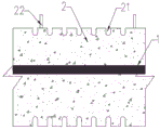
FIG. 1 is a schematic elevation structure view of a prefabricated non-dismantling post-cast strip template in the embodiment;
FIG. 2 is a side view of FIG. 1;
fig. 3 is a schematic elevation structure view of the water stop steel plate in the embodiment.
In the figure: the water stop steel plate comprises a water stop steel plate 1, a side flange 11, a through hole 12, a concrete template 2, a clamping groove 21, a hanging ring 22 and a reinforcing mesh 3.
Detailed Description
The present invention will be further explained with reference to the drawings and examples.
Example (b):
as shown in the figures, the prefabricated non-dismantling post-cast strip formwork provided by the embodiment comprises a water-stopping steel plate 1 and a concrete formwork 2 which is integrally in a three-dimensional structure, wherein the water-stopping steel plate 1 is rectangular, and the left side and the right side of the water-stopping steel plate 1 are bent downwards to form side flanges 11; the water stop steel plate 1 is embedded in the middle of the concrete template 2, and the left end and the right end of the water stop steel plate extend out of the concrete template 2; at least one reinforcing mesh 3 which penetrates through the water stop steel plate 1 in the middle and is vertically arranged is arranged in the concrete template 2; a plurality of clamping grooves 21 used for clamping the reinforcing steel bars are arranged at the upper end and/or the lower end of the concrete template 2 at intervals along the length direction of the concrete template 2, and the depth of each clamping groove 21 is larger than the diameter of the reinforcing steel bar to be clamped.
The reinforcing mesh 3 in this embodiment is formed by connecting a plurality of vertical reinforcing bars and transverse reinforcing bars, and is in a lattice shape. A plurality of through holes 12 for penetrating through the vertical steel bars in the steel bar net 3 are arranged in the middle of the water stop steel plate 1 at intervals along the length direction of the water stop steel plate. After the reinforcing mesh 3 is arranged, the flexural strength of the concrete template can be guaranteed, and the quality of the prefabricated template in the hoisting process can be guaranteed.
The thickness of the concrete formwork 2 is 120 mm. A plurality of hanging rings 22 are provided at intervals along the length direction of the upper end surface of the concrete form 2. The lifting rings 22 are made of phi 16 first-grade steel and fixed on the concrete formwork 2 in an embedded mode, and each lifting ring 22 is arranged every 3m and can be arranged at an interval of 6m in the longest.
When being applied to the installation of the double-layer bidirectional reinforcing mesh, the post-cast strip template in the embodiment is simply positioned after the bottom reinforcing mesh is laid, then the prefabricated concrete template 2 is hoisted and installed, after the hoisting is carried out to the installation position, the lower reinforcing steel bars are completely adjusted to the clamping grooves 21 by the adjustment position, then the elevation and the verticality of the concrete template 2 are adjusted, the post-cast strip template is fixed by a steel pipe, and the prefabricated concrete template is prevented from overturning due to touch.
Finally, it should be noted that the above embodiments are only used for illustrating the technical solutions of the present invention and not for limiting the technical solutions, and although the applicant has described the present invention in detail with reference to the preferred embodiments, those skilled in the art should understand that those modifications or equivalent substitutions to the technical solutions of the present invention can be made without departing from the spirit and scope of the technical solutions, and all the modifications and equivalent substitutions should be covered by the claims of the present invention.
Claims (6)
1. A prefabricated disassembly-free post-cast strip template comprises a water-stopping steel plate (1), wherein the water-stopping steel plate (1) is rectangular, the left side and the right side of the water-stopping steel plate (1) are bent downwards to form side flanges (11), and the prefabricated disassembly-free post-cast strip template is characterized in that the water-stopping steel plate (1) is embedded in the middle of a concrete template (2), and the left end and the right end of the water-stopping steel plate extend out of the concrete template (2); at least one reinforcing mesh (3) with the middle part penetrating through the water stop steel plate (1) and vertically arranged is arranged in the concrete template (2); a plurality of clamping grooves (21) used for clamping reinforcing steel bars are arranged at the upper end and/or the lower end of the concrete template (2) at intervals along the length direction of the concrete template (2).
2. The prefabricated removal-free post-cast strip formwork as claimed in claim 1, wherein the depth of the clamping groove (21) is larger than the diameter of a steel bar to be clamped.
3. The prefabricated disassembly-free post-cast strip template as claimed in claim 1 or 2, wherein the reinforcing mesh (3) is formed by connecting a plurality of vertical reinforcing bars and transverse reinforcing bars and is in a lattice shape.
4. The prefabricated disassembly-free post-cast strip template as claimed in claim 3, wherein a plurality of through holes (12) for penetrating vertical steel bars in the steel bar net piece (3) are formed in the middle of the water stop steel plate (1) at intervals along the length direction of the water stop steel plate.
5. The prefabricated removal-free post-cast strip formwork as claimed in claim 1, 2 or 4, wherein the thickness of the concrete formwork (2) is 100-150 mm.
6. The precast post-cast strip formwork of claim 1, 2 or 4, wherein a plurality of hanging rings (22) are provided at intervals along the length direction of the concrete formwork (2) on the upper end surface thereof.
Priority Applications (1)
| Application Number | Priority Date | Filing Date | Title |
|---|---|---|---|
| CN202121377625.1U CN214832930U (en) | 2021-06-21 | 2021-06-21 | Prefabricated non-dismantling post-pouring strip template |
Applications Claiming Priority (1)
| Application Number | Priority Date | Filing Date | Title |
|---|---|---|---|
| CN202121377625.1U CN214832930U (en) | 2021-06-21 | 2021-06-21 | Prefabricated non-dismantling post-pouring strip template |
Publications (1)
| Publication Number | Publication Date |
|---|---|
| CN214832930U true CN214832930U (en) | 2021-11-23 |
Family
ID=78806998
Family Applications (1)
| Application Number | Title | Priority Date | Filing Date |
|---|---|---|---|
| CN202121377625.1U Active CN214832930U (en) | 2021-06-21 | 2021-06-21 | Prefabricated non-dismantling post-pouring strip template |
Country Status (1)
| Country | Link |
|---|---|
| CN (1) | CN214832930U (en) |
-
2021
- 2021-06-21 CN CN202121377625.1U patent/CN214832930U/en active Active
Similar Documents
| Publication | Publication Date | Title |
|---|---|---|
| CN110761322B (en) | Cast-in-place pipe gallery side wall horizontal construction joint reinforcing structure and construction method thereof | |
| CN106759439B (en) | Tower crane foundation for foundation pit and construction method thereof | |
| CN105569224A (en) | Concrete-filled steel tube edge restraint overlapping integrated shear wall and preparing and installation methods thereof | |
| CN107327050B (en) | Disassembly-free basement exterior wall flanging unilateral formwork supporting device and construction method | |
| CN109403545B (en) | High-assembly-rate steel pipe concrete frame structure system and connection method | |
| CN112878535B (en) | Precast concrete wallboard connecting structure and construction method thereof | |
| CN211007021U (en) | Prefabricated balcony of prefabricated building | |
| CN212656384U (en) | High-strength concrete connecting piece, high-strength concrete post-cast assembled frame system and support frame | |
| CN214832930U (en) | Prefabricated non-dismantling post-pouring strip template | |
| CN216664766U (en) | Assembled parapet that cornices | |
| CN214739120U (en) | Prefabricated toilet falls board | |
| CN214143789U (en) | Tower crane foundation on foundation pit slope | |
| CN205382595U (en) | Integral shear force wall of steel pipe concrete edge constraint coincide | |
| CN212613905U (en) | Mounting structure of elevator in existing building | |
| CN218405981U (en) | Prefabricated overhanging lower hanging type floor edge sealing structure and edge sealing floor installation structure | |
| CN220868506U (en) | Prefabricated cavity wall splicing structure and water service wall | |
| CN216197017U (en) | Steel beam concrete column core node | |
| CN221118738U (en) | Prefabricated balcony slab | |
| CN216615945U (en) | Tower crane foundation and bottom plate coincide integral structure | |
| CN114108672B (en) | Tower crane foundation and bottom plate superposed integrated structure and construction method thereof | |
| CN215630818U (en) | Connecting node structure of PTW wallboard and foundation | |
| CN213204438U (en) | Semi-prefabricated and semi-cast-in-place building component | |
| CN220954580U (en) | General embedded part structure of curtain wall and overhanging outer scaffold | |
| RU221195U1 (en) | Glass-type precast reinforced concrete column sill | |
| CN216920378U (en) | Assembled underground well soil retaining device |
Legal Events
| Date | Code | Title | Description |
|---|---|---|---|
| GR01 | Patent grant | ||
| GR01 | Patent grant |