CN214831829U - Buffer stop and damping combined energy consumption type bridge anti-seismic structure - Google Patents
Buffer stop and damping combined energy consumption type bridge anti-seismic structure Download PDFInfo
- Publication number
- CN214831829U CN214831829U CN202022581866.XU CN202022581866U CN214831829U CN 214831829 U CN214831829 U CN 214831829U CN 202022581866 U CN202022581866 U CN 202022581866U CN 214831829 U CN214831829 U CN 214831829U
- Authority
- CN
- China
- Prior art keywords
- seismic
- steel
- steel corbel
- plate
- buffer stop
- Prior art date
- Legal status (The legal status is an assumption and is not a legal conclusion. Google has not performed a legal analysis and makes no representation as to the accuracy of the status listed.)
- Active
Links
Images


Abstract
The utility model relates to the technical field of bridge anti-seismic, in particular to a buffer stop and damping combined energy-consumption type bridge anti-seismic structure, which comprises a steel corbel assembly, a top plate, a web plate with a rubber anti-seismic layer on the inner side surface, a cubic slider, a damping device and a connecting device, wherein the steel corbel assembly is fixed above the side wall of a pier, the top plate is fixed at the bottom of a main beam, one section of two web plates is connected with one end of the bottom of the top plate through an angle steel, and the other end of the two web plates is connected with the top of the steel corbel; the damping is arranged on the front side of the rear block of the cubic sliding block, the two sliding blocks are connected with the connecting device through the cylindrical blocks protruding from the left side and the right side, and in the connecting device, wavy stripes are arranged at the contact part of the two sliding blocks and the cylindrical blocks to increase friction. The utility model discloses can restrict the bridge in the same direction as bridge of the roof beam body and pier to too big displacement, avoid taking place the roof beam phenomenon that falls, absorbed energy to reduce the earthquake and to the damage of bridge, absorb seismic energy.
Description
Technical Field
The utility model relates to a bridge antidetonation technical field especially relates to a buffer stop and damping combine power consumption type bridge earthquake-resistant structure.
Background
With the increasing economic growth of China, the investment of each project which is beneficial to social development and improvement of the livelihood is more and more, the basic work is also rapidly developed, and the road and bridge traffic construction is very important for the development of one region. The bridge is also a junction in a traffic route, and once an accident occurs to the bridge, a series of butterfly effects such as economy, society and the like can be generated. Therefore, the safety performance and stability of the bridge such as earthquake resistance are worth discussing.
China has more than million under construction and built bridge girders. China has ever-changing topography, the shadows of bridges are arranged in various terrains and regions, and some regions belong to earthquake-prone areas. Bridges in these areas present many safety hazards. Once an earthquake happens, the bridge is easy to collapse, and great economic loss is brought to people, and even the life safety of people is threatened. And meanwhile, traffic is blocked, so that difficulties such as rescue are serious.
The failure mode of the bridge structure in earthquake mainly comprises the following steps: the upper beam body falls off, the support is damaged, the pile foundation pier column cracks, the beam body is damaged by collision, and the like.
Therefore, a novel bridge anti-seismic baffle structure needs to be designed and developed, which can not only play the role of anti-seismic energy consumption in earthquake, but also limit the displacement of the upper beam body of the bridge along the bridge direction.
SUMMERY OF THE UTILITY MODEL
The utility model aims to overcome current technique not enough, provide a dog and damping combine power consumption type bridge earthquake-resistant structure, can restrict the following bridge of the roof beam body and pier to too big displacement, avoid taking place the roof beam phenomenon of falling, through the friction, the spring compression, rubber deformation buffering etc to the absorbed energy, so that reduce the earthquake to the damage of bridge, absorb seismic energy.
The utility model relates to a bridge antidetonation technical field especially relates to a buffer stop and damping combination energy consumption type bridge antidetonation structure, including steel corbel and antidetonation device, the steel corbel passes through steel corbel bolt fastening in the lateral wall top of pier, the edge connection has two longitudinal webs and two transverse webs at the top of steel corbel, the top of steel corbel evenly is equipped with a plurality of dampings, the top of damping is connected with the bottom of sheet metal, the top of longitudinal web and transverse web is connected with the roof, the roof is fixed in the bottom of girder through the bolt; the anti-seismic device is placed on the thin plate and comprises two anti-seismic baffles, two anti-seismic sliding blocks and a fixing device, the anti-seismic sliding blocks are of a cubic structure and are connected through steel springs, and the anti-seismic baffles are fixed at two ends of the anti-seismic sliding blocks through the fixing device.
The steel bracket comprises a steel bracket top plate, a steel bracket web plate, a steel bracket bottom plate and a steel bracket side plate, and threaded holes for steel bracket bolts to penetrate through are formed in the steel bracket side plate; the steel bracket top plate and the steel bracket bottom plate are horizontally arranged, and two parallel steel bracket webs are vertically welded between the steel bracket top plate and the steel bracket bottom plate; the outer wall of the steel bracket web plate is respectively connected with the steel bracket top plate, the steel bracket bottom plate and one side of the steel bracket side plate.
A cylindrical bulge is arranged in the middle of the outer side wall of the anti-seismic slide block; the fixing device is a fixed crawler belt, a gap is formed between the anti-seismic baffle and the anti-seismic slide block, and two side walls of the anti-seismic baffle are fixedly connected with two ends of the fixed crawler belt through fixing bolts.
A sliding groove is formed in the middle of the fixing device, and the width of the sliding groove is equal to the outer diameter of the protrusion; and the outer surface of the sliding groove is provided with protruding stripes.
The thin plate is a high-toughness thin plate, and the upper surface of the thin plate is a rough contact surface.
And thin rubber layers are covered on the inner walls of the longitudinal web plate and the transverse web plate and on the outer side wall of the anti-seismic baffle.
The longitudinal web, the transverse web and the anti-seismic baffle are all high-toughness and high-strength concrete slabs.
And an angle steel is arranged below the outer wall of the transverse web plate and fixed on the steel bracket top plate through a fixing bolt.
The beneficial effects of the utility model reside in that:
1) the shock absorption device is composed of two cubic anti-seismic sliding blocks connected by a steel spring and fixed by two anti-seismic baffles and a fixing device, can convert earthquake energy into steel spring deformation to absorb energy and consume energy through friction, and can effectively buffer longitudinal displacement caused by the earthquake through the steel spring deformation.
2) A plurality of damps are connected to the steel corbel top plate, and the sheet metal that high tenacity and contact surface are coarse is connected again in the damping, can further consume seismic energy through the friction, reduces longitudinal displacement. Meanwhile, the energy can be absorbed by the deformation of the damping spring, and the transverse displacement is slowed down and limited.
3) The rubber thin layers cover the inner sides of the longitudinal web and the transverse web and the inner side of the anti-seismic baffle, so that the impact caused by transverse displacement and longitudinal displacement in a large range can be buffered, the seismic energy is absorbed, the safety of the device can be effectively protected, and the device is not damaged or loses efficacy due to factors such as impact.
4) The utility model discloses convenient for material collection, simple structure, the construction is convenient, and the antidetonation effect is showing.
Drawings
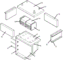
Fig. 1 is a schematic exploded view of the present invention;
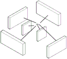
FIG. 2 is an exploded perspective view of the shock absorbing device;
FIG. 3 is an enlarged view of a thin rubber layer;
FIG. 4 is an enlarged three-dimensional view of the fixation device;
fig. 5 is a forward bridge layout diagram of the present invention.
In the figure: 1 steel corbel bottom plate, 2 steel corbel webs, 3 steel corbel top plates, 4 dampers, 5 thin plates, 6 steel corbel bolts, 7 steel corbel side plates, 8 longitudinal webs, 9 angle steels, 10 transverse webs, 11 bolts, 12 top plates, 13 anti-seismic baffles, 14 anti-seismic sliders, 15 fixing devices, 16 steel springs, 17 protruding stripes, 18 rubber thin layers, 19 piers and 23 main beams.
Detailed Description
The following further description of the present invention
Please refer to fig. 1-5.
The utility model discloses a buffer stop and damping combined energy-consuming type bridge anti-seismic structure, including steel corbels and anti-seismic devices, the steel corbels are fixed above the side wall of a pier 19 through steel corbel bolts 6, the top edge of the steel corbel is connected with two longitudinal webs 8 and two transverse webs 10, the top of the steel corbel is uniformly provided with a plurality of dampers 4, the top of each damper 4 is connected with the bottom of a thin plate 5, the tops of the longitudinal webs 8 and the transverse webs 10 are connected with a top plate 12, and the top plate 12 is fixed at the bottom of a main beam 23 through bolts 11; an anti-seismic device is placed on the thin plate 5, the anti-seismic device comprises two anti-seismic baffles 13, two anti-seismic sliders 14 and a fixing device 15, the anti-seismic sliders 14 are of a cubic structure, the two anti-seismic sliders 14 are connected through a steel spring 16, the anti-seismic baffles 13 are fixed at two ends of the anti-seismic sliders 14 through the fixing device 15, the damping device is composed of the two cubic anti-seismic sliders 14 connected through the steel spring 16 and fixed by the two anti-seismic baffles 13 and the fixing device 15, the anti-seismic device can convert earthquake energy into deformation of the steel spring 16 to absorb energy and friction to consume energy, and longitudinal displacement caused by an earthquake can be effectively buffered through deformation of the steel spring 16; the steel corbel top plate 3 is connected with a plurality of dampers 4, the dampers 4 are connected with high-toughness thin plates 5 with rough contact surfaces, earthquake energy can be further consumed through friction, longitudinal displacement is reduced, energy can be absorbed through deformation of the damping springs, and transverse displacement is slowed down and limited; the multiple dampers 4 act together to enable the stress to be uniform, and the possibility of single-point damage is reduced.
The steel bracket comprises a steel bracket top plate 3, a steel bracket web 2, a steel bracket bottom plate 1 and a steel bracket side plate 7, wherein a threaded hole for a steel bracket bolt 6 to pass through is formed in the steel bracket side plate 7; the steel corbel top plate 3 and the steel corbel bottom plate 1 are horizontally arranged, and two parallel steel corbel webs 2 are vertically welded between the steel corbel top plate and the steel corbel bottom plate; the outer wall of the steel bracket web 2 is respectively connected with the steel bracket top plate 3, the steel bracket bottom plate 1 and one side of the steel bracket side plate 7.
A cylindrical bulge is arranged in the middle of the outer side wall of the anti-seismic slide block 14; the fixing device 15 is a fixed crawler belt, a gap is formed between the anti-seismic baffle 13 and the anti-seismic slide block 14, and two side walls of the anti-seismic baffle 13 are fixedly connected with two ends of the fixed crawler belt through fixing bolts.
A sliding groove is formed in the middle of the fixing device 15, and the width of the sliding groove is equal to the outer diameter of the protrusion; the outer surface of the sliding groove is provided with protruding stripes 17, friction is increased, energy is consumed, and longitudinal displacement can be effectively limited.
The sheet 5 is a high-toughness sheet, and the upper surface thereof is a rough contact surface.
The rubber thin layers 18 cover the inner walls of the longitudinal web 8 and the transverse web 10 and the outer side wall of the anti-seismic baffle 13, so that the impact caused by transverse displacement and longitudinal displacement when the transverse displacement and the longitudinal displacement are larger can be buffered, simultaneously, the earthquake energy is absorbed, the safety of the device can be effectively protected, and the device is not damaged or loses efficacy due to factors such as impact.
The longitudinal web 8, the transverse web 10 and the anti-seismic baffle 13 are all high-toughness high-strength concrete slabs.
And an angle steel 9 is arranged below the outer wall of the two transverse webs 10, and the angle steel 9 is fixed on the steel bracket top plate 3 through a fixing bolt.
The above mentioned is only the embodiment of the present invention, not the limitation of the patent scope of the present invention, all the equivalent transformations made by the contents of the specification and the drawings or the direct or indirect application in the related technical field are included in the patent protection scope of the present invention.
Claims (8)
1. The utility model provides a buffer stop and damping combination power consumption type bridge earthquake-resistant structure which characterized in that: the steel corbel anti-seismic device comprises a steel corbel and an anti-seismic device, wherein the steel corbel is fixed above a side wall of a pier (19) through a steel corbel bolt (6), the top edge of the steel corbel is connected with two longitudinal webs (8) and two transverse webs (10), a plurality of dampers (4) are uniformly arranged at the top of the steel corbel, the top of each damper (4) is connected with the bottom of a thin plate (5), the tops of the longitudinal webs (8) and the transverse webs (10) are connected with a top plate (12), and the top plate (12) is fixed at the bottom of a main beam (23) through a bolt (11); the anti-seismic device is placed on the thin plate (5), and comprises two anti-seismic baffles (13), two anti-seismic sliders (14) and a fixing device (15), wherein the anti-seismic sliders (14) are of a cubic structure and are connected through steel springs (16), and the anti-seismic baffles (13) are fixed at two ends of the anti-seismic sliders (14) through the fixing device (15).
2. The combination buffer stop and damping energy dissipation type bridge anti-seismic structure according to claim 1, wherein: the steel bracket comprises a steel bracket top plate (3), a steel bracket web plate (2), a steel bracket bottom plate (1) and a steel bracket side plate (7), wherein a threaded hole for a steel bracket bolt (6) to pass through is formed in the steel bracket side plate (7); the steel corbel top plate (3) and the steel corbel bottom plate (1) are horizontally arranged, and two parallel steel corbel webs (2) are vertically welded between the steel corbel top plate and the steel corbel bottom plate; the outer wall of the steel corbel web (2) is connected with the steel corbel top plate (3), the steel corbel bottom plate (1) and one side of the steel corbel side plate (7) respectively.
3. The combination buffer stop and damping energy dissipation type bridge anti-seismic structure according to claim 2, wherein: a cylindrical bulge is arranged in the middle of the outer side wall of the anti-seismic sliding block (14); the fixing device (15) is a fixed crawler belt, a gap is formed between the anti-seismic baffle (13) and the anti-seismic slide block (14), and two side walls of the anti-seismic baffle (13) are fixedly connected with two ends of the fixed crawler belt through fixing bolts.
4. The combination buffer stop and damping energy dissipation type bridge anti-seismic structure according to claim 3, wherein: a sliding groove is formed in the middle of the fixing device (15), and the width of the sliding groove is equal to the outer diameter of the protrusion; the outer surface of the sliding groove is provided with protruding stripes (17).
5. The combination buffer stop and damping energy dissipation type bridge anti-seismic structure according to claim 4, wherein: the thin plate (5) is a high-toughness thin plate, and the upper surface of the thin plate is a rough contact surface.
6. The combination buffer stop and damping energy dissipation type bridge anti-seismic structure according to claim 5, wherein: the inner walls of the longitudinal web (8) and the transverse web (10) and the outer side wall of the anti-seismic baffle (13) are covered with thin rubber layers (18).
7. The combination buffer stop and damping energy dissipation type bridge anti-seismic structure according to claim 6, wherein: the longitudinal web (8), the transverse web (10) and the anti-seismic baffle (13) are all high-toughness high-strength concrete slabs.
8. The combination buffer stop and damping energy dissipation type bridge anti-seismic structure according to claim 7, wherein: and an angle steel (9) is arranged below the outer wall of the two transverse webs (10), and the angle steel (9) is fixed on the steel corbel top plate (3) through a fixing bolt.
Priority Applications (1)
| Application Number | Priority Date | Filing Date | Title |
|---|---|---|---|
| CN202022581866.XU CN214831829U (en) | 2020-11-10 | 2020-11-10 | Buffer stop and damping combined energy consumption type bridge anti-seismic structure |
Applications Claiming Priority (1)
| Application Number | Priority Date | Filing Date | Title |
|---|---|---|---|
| CN202022581866.XU CN214831829U (en) | 2020-11-10 | 2020-11-10 | Buffer stop and damping combined energy consumption type bridge anti-seismic structure |
Publications (1)
| Publication Number | Publication Date |
|---|---|
| CN214831829U true CN214831829U (en) | 2021-11-23 |
Family
ID=78757111
Family Applications (1)
| Application Number | Title | Priority Date | Filing Date |
|---|---|---|---|
| CN202022581866.XU Active CN214831829U (en) | 2020-11-10 | 2020-11-10 | Buffer stop and damping combined energy consumption type bridge anti-seismic structure |
Country Status (1)
| Country | Link |
|---|---|
| CN (1) | CN214831829U (en) |
-
2020
- 2020-11-10 CN CN202022581866.XU patent/CN214831829U/en active Active
Similar Documents
| Publication | Publication Date | Title |
|---|---|---|
| CN201865044U (en) | Multifunctional quake damping and isolating support seat of bridge | |
| CN202519577U (en) | Bridge cable earthquake-reducing limiter | |
| CN214831829U (en) | Buffer stop and damping combined energy consumption type bridge anti-seismic structure | |
| CN201184000Y (en) | Damper for limb-connecting shear force wall girder-connecting energy consumption | |
| CN111926686A (en) | Energy-consumption buffering type spacing bridge anti-seismic stop block structure with steel springs | |
| CN210263128U (en) | A antidetonation dissipation structure and gravity type retaining wall for among gravity type retaining wall | |
| CN210657965U (en) | Bridge supporting structure | |
| CN215164549U (en) | Collision sliding energy consumption type bridge anti-seismic stop block structure with steel springs | |
| CN112391939A (en) | Buffer stop and damping combined energy consumption type bridge anti-seismic structure | |
| CN209836783U (en) | Anti-seismic, shock-absorption and anti-beam-falling steel sliding plate support for urban overpass bridge | |
| CN215165290U (en) | Metal damping device with limiting capacity for navigation aqueduct structure | |
| CN112391941A (en) | Bridge anti-seismic structure combining three energy consumption forms | |
| CN212375694U (en) | Friction and spring combined energy consumption type bridge anti-seismic stop block structure | |
| CN212335745U (en) | Foam metal reinforced bridge anti-collision stop block | |
| CN210031474U (en) | Railway bridge is with shock attenuation power consumption beam device that prevents falling | |
| CN104775548A (en) | Column through type corrugated steel plate energy dissipation shear wall structure | |
| CN214459557U (en) | Bridge anti-seismic structure combining three energy consumption forms | |
| CN211472134U (en) | Bridge shock-absorbing structure with energy consumption reset function | |
| CN204491399U (en) | A kind of novel anti-fall girder apparatus | |
| CN103147392A (en) | Steel bridge function separating shock-absorbing support | |
| CN111287071A (en) | Multidirectional buffering, limiting and energy-consuming resettable bridge anti-seismic stop block structure | |
| CN111764260A (en) | Bridge buffer and antidetonation bridge that takes precautions against earthquakes | |
| CN213740552U (en) | Novel truss bridge structure capable of preventing rock fall impact | |
| CN203346787U (en) | Flat steel spring plate expansion joint | |
| CN214301221U (en) | Swing type buffering energy-consumption type bridge anti-seismic stop block structure |
Legal Events
| Date | Code | Title | Description |
|---|---|---|---|
| GR01 | Patent grant | ||
| GR01 | Patent grant |