CN212375694U - Friction and spring combined energy consumption type bridge anti-seismic stop block structure - Google Patents
Friction and spring combined energy consumption type bridge anti-seismic stop block structure Download PDFInfo
- Publication number
- CN212375694U CN212375694U CN202021752675.9U CN202021752675U CN212375694U CN 212375694 U CN212375694 U CN 212375694U CN 202021752675 U CN202021752675 U CN 202021752675U CN 212375694 U CN212375694 U CN 212375694U
- Authority
- CN
- China
- Prior art keywords
- hollow cube
- wall
- steel
- steel bracket
- friction
- Prior art date
- Legal status (The legal status is an assumption and is not a legal conclusion. Google has not performed a legal analysis and makes no representation as to the accuracy of the status listed.)
- Expired - Fee Related
Links
Images


Abstract
The utility model relates to the technical field of bridge anti-seismic, in particular to a friction and spring combined energy-consumption type bridge anti-seismic stop block structure, which comprises a steel corbel assembly, a top plate, web plates, a hollow cube and a ball body, wherein the steel corbel assembly is fixed above the side wall of a pier, the top plate is fixed at the bottom of a main beam, one end of each of the two web plates is connected with one end of the bottom of the top plate, and the other end of each web plate is connected with the top of the steel corbel assembly; the hollow cube is of a hollow cube structure, and first dampers connected with the left outer wall and the right outer wall of the hollow cube and the inner walls of the two webs are arranged between the left outer wall and the right outer wall of the hollow cube and the inner walls of the two webs; the sphere is arranged in the inner cavity of the hollow cube, and a second damper connected with the sphere is arranged between the outer wall of the sphere and the inner cavity of the hollow cube. The utility model discloses can restrict the bridge in the same direction as bridge of the roof beam body and pier to too big displacement, avoid taking place the roof beam phenomenon that falls, absorbed energy to reduce the earthquake and to the damage of bridge, absorb seismic energy.
Description
Technical Field
The utility model relates to a bridge antidetonation technical field especially relates to a friction and spring combination power consumption type bridge antidetonation dog structure.
Background
In recent years, the economy of China is rapidly increased, the national investment of each project which is beneficial to social development and improvement of the livelihood is more and more, the capital construction work is rapidly developed, and the road traffic construction plays an important role in regional economic development. The bridge is a junction in a traffic route, once an accident occurs to the bridge, a series of economic problems and social effects can be brought, so that the safety performance and the stability degree of the bridge need to be paid attention and paid attention.
The number of bridges built and built in China is more than million, bridges are built in various terrains and regions, and the potential safety hazard exists in some regions due to the fact that the bridges are located in the geographical positions of earthquake-prone zones. Once an earthquake comes, the bridge is easy to damage or even collapse due to the structural characteristics, so that huge economic loss is brought, life safety of people is threatened, an island effect is formed, and serious difficulty is brought to rescue work after the earthquake.
The bridge structure mainly breaks in earthquake in the forms of upper beam body falling, support seat breaking, pile foundation pier column cracking, beam body collision breaking and the like. However, most of bridges in China currently adopt measures for resisting earthquake that reinforced concrete stop blocks are arranged on two sides of the top of a pier capping beam, the method can limit the transverse bridge-direction displacement of an upper beam body to a certain extent, but local damage is easily caused during collision, and the method has no effect of restraining the displacement along the bridge direction.
Therefore need design and develop a neotype bridge antidetonation dog structure, can effectively exert the antidetonation effect when the earthquake, can restrict the bridge forward displacement of bridge upper portion roof beam body again, self impaired degree when will reduce the dog effect simultaneously.
SUMMERY OF THE UTILITY MODEL
An object of the utility model is to overcome prior art not enough, provide a friction and spring combination power consumption type bridge antidetonation dog structure, can restrict the bridge in the same direction as the bridge of the roof beam body and pier to too big displacement, avoid taking place the roof beam phenomenon of falling, through friction and spring compression etc. to the absorbed energy, so that reduce the earthquake to the damage of bridge, absorb seismic energy.
In order to realize the utility model discloses a purpose, the utility model discloses a technical scheme do:
the utility model discloses a friction and spring combined energy-consumption type bridge anti-seismic stop block structure, which comprises a steel corbel assembly, a top plate, web plates, a hollow cube and a ball body, wherein the steel corbel assembly is fixed above the side wall of a pier, the top plate is fixed at the bottom of a main beam, one end of each of the two web plates is connected with one end of the bottom of the top plate, and the other end of each web plate is connected with the top of the steel corbel assembly; the hollow cube is of a hollow cube structure, and first dampers connected with the left outer wall and the right outer wall of the hollow cube and the inner walls of the two webs are arranged between the left outer wall and the right outer wall of the hollow cube and the inner walls of the two webs; the sphere is arranged in the inner cavity of the hollow cube, and a second damper connected with the sphere is arranged between the outer wall of the sphere and the inner cavity of the hollow cube.
The steel bracket assembly comprises a steel bracket bottom plate, a steel bracket web plate, a steel bracket top plate and a steel bracket side plate, the steel bracket side plate is fixed above the side wall of the pier through a steel bracket bolt, the steel bracket top plate and the steel bracket bottom plate are arranged in parallel and are respectively fixed at the top and the bottom of the steel bracket side plate, and the steel bracket web plate is fixed between the steel bracket top plate and the steel bracket bottom plate; the bottom of web is fixed in through first bolt on the steel corbel roof.
The hollow cube with be equipped with spill dog between roof, the steel corbel roof, spill dog is close to form on the lateral wall of hollow cube one side with the draw-in groove of hollow cube matching block, its keep away from one side lateral wall of hollow cube respectively with roof, steel corbel roof contact.
The angle steel is arranged between the two ends of the outer wall of the web plate and fixedly connected with the top plate, the steel bracket top plate and the outer side through angle steel fixing bolts.
A plurality of first dampers are arranged between the hollow cubes and the web.
The surface of the sphere is rough, and the same second damping is arranged between the outer wall of the sphere and the six inner walls of the inner cavity of the hollow cube.
And the first damper and the second damper are both spring anti-seismic dampers.
The web is a high-toughness concrete slab.
The beneficial effects of the utility model reside in that:
1) the utility model discloses damping device is hollow cube and spheroid and the damped collocation of second, can become the energy absorption energy of spring deformation with the energy conversion of earthquake, and can imitate the vertical displacement that the buffering earthquake leads to through spring deformation.
2) The utility model discloses a set up the spill dog and make hollow cube can produce the friction with it at vibrations in-process to consume seismic energy, and the spill dog can further consume seismic energy again with the friction of roof, steel bracket roof, thereby realize the shock attenuation effect.
3) The utility model discloses a web and first damped use can effectively restrict the displacement in the same direction as the bridge between top girder and the pier about setting up.
4) The utility model discloses convenient for material collection, simple structure, the construction is convenient, and the antidetonation effect is showing.
Drawings
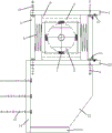
Fig. 1 is a front view of the present invention;
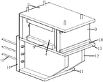
fig. 2 is a three-dimensional perspective view of the present invention;
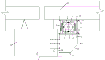
FIG. 3 is a schematic diagram of the arrangement of the present invention along the direction of the bridge;
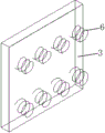
FIG. 4 is a schematic diagram of the distribution of the first damping in the present invention;
FIG. 5 is a schematic structural view of a middle angle steel of the present invention;
fig. 6 is a schematic diagram of a middle portion of the structure of the present invention.
In the figure: 1 steel bracket subassembly, 2 roofs, 3 webs, 4 hollow cubes, 5 spheres, 6 first damps, 7 first damps, 8 first bolts, 9 spill dogs, 10 second bolts, 11 steel bracket bottom plates, 12 steel bracket webs, 13 steel bracket roofs, 14 steel bracket side plates, 15 steel bracket bolts, 16 angle steel, 17 angle steel fixing bolts, 20 piers, 21 girders.
Detailed Description
The following further description of the present invention:
referring to figures 1-6 of the drawings,
the utility model discloses a friction and spring combined energy-consumption type bridge anti-seismic stop block structure, which comprises a steel corbel component 1, a top plate 2, web plates 3, a hollow cube 4 and a ball body 5, wherein the steel corbel component 1 is fixed above the side wall of a pier 20, the top plate 2 is fixed at the bottom of a main beam 21, one end of each of the two web plates 3 is connected with one end of the bottom of the top plate 2, and the other end of each web plate is connected with the top of the steel corbel component 1; the hollow cube 4 is of a hollow cube structure, and first dampers 6 connected with the left outer wall and the right outer wall of the hollow cube 4 and the inner walls of the two webs 3 are arranged between the left outer wall and the right outer wall of the hollow cube 4 and the inner walls of the two webs 3; the ball body 5 is arranged in the inner cavity of the hollow cube 4, a second damper 7 connected with the ball body is arranged between the outer wall of the ball body and the inner cavity of the hollow cube 4, and the displacement between the upper main beam 21 and the pier 20 in the bridge direction can be effectively limited through the first damper 6 between the web 3 and the hollow cube 4; through the second damping 7 between the inner wall of the hollow cube 4 and the sphere 5, the energy of earthquake can be converted into the spring deformation absorption energy, and the longitudinal displacement caused by the earthquake can be buffered through the spring deformation effect.
The steel bracket assembly 1 comprises a steel bracket bottom plate 11, a steel bracket web plate 12, a steel bracket top plate 13 and a steel bracket side plate 14, the steel bracket side plate 14 is fixed above the side wall of the pier 20 through a steel bracket bolt 15, the steel bracket top plate 13 and the steel bracket bottom plate 11 are arranged in parallel and fixed to the top and the bottom of the steel bracket side plate 14 respectively, and the steel bracket web plate 12 is fixed between the steel bracket top plate 13 and the steel bracket bottom plate 11; the bottom of the web 3 is fixed on the steel corbel top plate 13 through a first bolt 8, and the bottom of the web is fixed on the top plate 2 through a second bolt 10.
A concave stop block 9 is arranged between the hollow cube 4 and the top plate 2 and the steel corbel top plate 13, a clamping groove matched with and clamped with the hollow cube 4 is formed in the side wall of one side of the concave stop block 9 close to the hollow cube 4, the side wall of one side far away from the hollow cube 4 is respectively contacted with the top plate 2 and the steel corbel top plate 13, the concave stop block 9 is contacted with the top plate 2 and the steel corbel top plate 13 without bolts, the size of the concave stop block is smaller than that of the top plate 2 and the steel corbel top plate 13, and the concave stop block 9 is arranged so that the hollow cube 4 can generate friction with the top plate 2 and the steel corbel top plate 13 in the vibration process, and; the friction between the concave stop block 9 and the top plate 2 and the steel bracket top plate 13 can further consume seismic energy, so that the damping effect is realized; during earthquake, firstly the concave stop block 9 and the hollow cube 4 move together, so that earthquake energy is consumed through friction, when the earthquake intensity reaches a certain value, the maximum static friction is achieved between the concave stop block 9 and the hollow cube 4, so that relative sliding is started, the earthquake energy is further absorbed, the first damper 6 can effectively stop the hollow cube 4 from being excessively displaced, and the hollow cube 4 is enabled not to be separated from the concave stop block 9.
The hollow cube 4 with be equipped with a plurality of first damping 6 between the web 3, constitute by a plurality of small-size spring damping of evenly distributed, so can increase the lifting surface area to reduce web 3 pressure, make web 3 safer, can not be sheared bad by the shearing force that first bolt 8 and first damping 6 produced, can also restrict lateral displacement simultaneously, convert seismic energy into the energy that spring compression and tensile absorbed.
The sphere 5 is rough in surface, the same second damping 7 is arranged between the outer wall of the sphere and the six inner walls of the inner cavity of the hollow cube 4, the sphere 5 with the rough surface is arranged on the inner side of the hollow cube 4, and the spring damping is arranged on the sphere 5 in front, back, left, right, up and down and is connected with the inner walls of the inner side of the hollow cube 4, so that the sphere 5 can be suspended in the hollow inner cavity, seismic energy can be absorbed through compression and stretching of the second damping 7, and transverse and longitudinal displacement can be buffered.
The first damper 6 and the second damper 7 are both spring anti-seismic dampers, such as steel springs.
The web 3 is a high-toughness concrete slab.
The above mentioned is only the embodiment of the present invention, not the limitation of the patent scope of the present invention, all the equivalent transformations made by the contents of the specification and the drawings or the direct or indirect application in the related technical field are included in the patent protection scope of the present invention.
Claims (8)
1. The utility model provides a friction and spring combination power consumption type bridge antidetonation dog structure which characterized in that: comprises a steel corbel component (1), a top plate (2), a web plate (3), a hollow cube (4) and a sphere (5),
the steel corbel assembly (1) is fixed above the side wall of the pier (20), the top plate (2) is fixed at the bottom of the main beam (21), one end of each of the two webs (3) is connected with one end of the bottom of the top plate (2), and the other end of each web is connected with the top of the steel corbel assembly (1);
the hollow cube (4) is of a hollow cube structure, and first dampers (6) connected with the left outer wall and the right outer wall of the hollow cube (4) and the inner walls of the two webs (3) are arranged between the left outer wall and the right outer wall of the hollow cube (4);
the sphere (5) is arranged in the inner cavity of the hollow cube (4), and a second damper (7) connected with the sphere is arranged between the outer wall of the sphere and the inner cavity of the hollow cube (4).
2. The friction and spring combined energy dissipation type bridge anti-seismic stop structure according to claim 1, wherein: the steel bracket assembly (1) comprises a steel bracket bottom plate (11), a steel bracket web plate (12), a steel bracket top plate (13) and steel bracket side plates (14), wherein the steel bracket side plates (14) are fixed above the side walls of the bridge pier (20) through steel bracket bolts (15), the steel bracket top plate (13) and the steel bracket bottom plate (11) are arranged in parallel and fixed to the top and the bottom of the steel bracket side plate (14) respectively, and the steel bracket web plate (12) is fixed between the steel bracket top plate (13) and the steel bracket bottom plate (11); the bottom of the web plate (3) is fixed on the steel corbel top plate (13) through a first bolt (8).
3. The friction and spring combined energy dissipation type bridge anti-seismic stop structure according to claim 2, wherein: hollow cube (4) with be equipped with spill dog (9) between roof (2), the steel corbel roof (13), spill dog (9) are close to form on the lateral wall of hollow cube (4) one side with the draw-in groove of hollow cube (4) matching block, it keeps away from one side lateral wall of hollow cube (4) respectively with roof (2), steel corbel roof (13) contact.
4. A friction and spring combined energy dissipation type bridge anti-seismic stop structure according to claim 3, wherein: roof (2), steel bracket roof (13) and the outside be equipped with angle steel (16) between the outer wall both ends of web (3), angle steel (16) pass through angle steel fixing bolt (17) fixed connection.
5. The friction and spring combined energy dissipation type bridge anti-seismic stop structure according to claim 1, wherein: a plurality of first dampers (6) are arranged between the hollow cubes (4) and the web (3).
6. The friction and spring combined energy dissipation type bridge anti-seismic stop structure according to claim 5, wherein: the surface of the sphere (5) is rough, and the same second damper (7) is arranged between the outer wall of the sphere and the six inner walls of the inner cavity of the hollow cube (4).
7. The friction and spring combined energy dissipation type bridge anti-seismic stop structure according to claim 6, wherein: the first damper (6) and the second damper (7) are both spring anti-seismic dampers.
8. The friction and spring combined energy dissipation type bridge anti-seismic stop structure according to claim 1, wherein: the web (3) is a high-toughness concrete slab.
Priority Applications (1)
| Application Number | Priority Date | Filing Date | Title |
|---|---|---|---|
| CN202021752675.9U CN212375694U (en) | 2020-08-20 | 2020-08-20 | Friction and spring combined energy consumption type bridge anti-seismic stop block structure |
Applications Claiming Priority (1)
| Application Number | Priority Date | Filing Date | Title |
|---|---|---|---|
| CN202021752675.9U CN212375694U (en) | 2020-08-20 | 2020-08-20 | Friction and spring combined energy consumption type bridge anti-seismic stop block structure |
Publications (1)
| Publication Number | Publication Date |
|---|---|
| CN212375694U true CN212375694U (en) | 2021-01-19 |
Family
ID=74173227
Family Applications (1)
| Application Number | Title | Priority Date | Filing Date |
|---|---|---|---|
| CN202021752675.9U Expired - Fee Related CN212375694U (en) | 2020-08-20 | 2020-08-20 | Friction and spring combined energy consumption type bridge anti-seismic stop block structure |
Country Status (1)
| Country | Link |
|---|---|
| CN (1) | CN212375694U (en) |
-
2020
- 2020-08-20 CN CN202021752675.9U patent/CN212375694U/en not_active Expired - Fee Related
Similar Documents
| Publication | Publication Date | Title |
|---|---|---|
| CN202913344U (en) | Seismic mitigation and isolation system applied to seismic resistance of long-span continuous beam of single-track railway | |
| CN105780640A (en) | Resettable shape memory alloy (SMA) multidimensional vibration isolating support | |
| CN206521689U (en) | A kind of energy-dissipating type Antivibration block device | |
| CN111926686A (en) | Energy-consumption buffering type spacing bridge anti-seismic stop block structure with steel springs | |
| CN212375694U (en) | Friction and spring combined energy consumption type bridge anti-seismic stop block structure | |
| CN111719469A (en) | Anti-collision isolation guardrail device in highway center | |
| CN111926687A (en) | Friction and spring combined energy consumption type bridge anti-seismic stop block structure | |
| CN113152253B (en) | Simply supported bridge anti-falling beam connecting device with dual guarantee | |
| Gimenez et al. | Md. Seismic isolation of bridges: devices, common practices in Japan, and examples of application | |
| CN112391941A (en) | Bridge anti-seismic structure combining three energy consumption forms | |
| CN215164549U (en) | Collision sliding energy consumption type bridge anti-seismic stop block structure with steel springs | |
| CN214245292U (en) | Bridge with bearing deformation structure | |
| CN216615454U (en) | Sliding damping shock absorption limiting device suitable for bridge | |
| CN214459557U (en) | Bridge anti-seismic structure combining three energy consumption forms | |
| CN212801180U (en) | Energy-consumption buffering type spacing bridge anti-seismic stop block structure with steel springs | |
| CN111287071A (en) | Multidirectional buffering, limiting and energy-consuming resettable bridge anti-seismic stop block structure | |
| CN214831829U (en) | Buffer stop and damping combined energy consumption type bridge anti-seismic structure | |
| CN217733721U (en) | Multi-friction damping energy dissipation reset anti-seismic stop block structure | |
| CN216615455U (en) | Steel spring reinforced multidirectional buffering limiting energy consumption type bridge anti-seismic stop block | |
| CN212270639U (en) | Multidirectional buffering, limiting and energy-consuming resettable bridge anti-seismic stop block structure | |
| CN113789715A (en) | Sliding damping shock absorption limiting device suitable for bridge | |
| CN111364348A (en) | Multiple damping buffering energy consumption type bridge anti-seismic stop block structure | |
| CN214783309U (en) | Multiple buffering bridge anti-seismic device that resets | |
| CN214301221U (en) | Swing type buffering energy-consumption type bridge anti-seismic stop block structure | |
| CN212375690U (en) | Multiple damping buffering energy consumption type bridge anti-seismic stop block structure |
Legal Events
| Date | Code | Title | Description |
|---|---|---|---|
| GR01 | Patent grant | ||
| GR01 | Patent grant | ||
| CF01 | Termination of patent right due to non-payment of annual fee |
Granted publication date: 20210119 Termination date: 20210820 |
|
| CF01 | Termination of patent right due to non-payment of annual fee |