CN214826236U - Multifunctional garbage classification vehicle - Google Patents
Multifunctional garbage classification vehicle Download PDFInfo
- Publication number
- CN214826236U CN214826236U CN202121223400.0U CN202121223400U CN214826236U CN 214826236 U CN214826236 U CN 214826236U CN 202121223400 U CN202121223400 U CN 202121223400U CN 214826236 U CN214826236 U CN 214826236U
- Authority
- CN
- China
- Prior art keywords
- garbage
- carriage
- area
- functional
- district
- Prior art date
- Legal status (The legal status is an assumption and is not a legal conclusion. Google has not performed a legal analysis and makes no representation as to the accuracy of the status listed.)
- Active
Links
Images


Abstract
The application discloses a multifunctional garbage classification vehicle, which comprises a chassis, a cockpit and a carriage, wherein the cockpit and the carriage are arranged on the chassis, a garbage can placing area, a cleaning area and a plurality of garbage throwing areas for containing different types of garbage are arranged in the carriage, a plurality of garbage throwing openings corresponding to the garbage throwing areas are formed in the side surface of the carriage, the cleaning area comprises at least one pair of hand washing grooves respectively arranged on two sides of the carriage, a movable box door capable of at least partially sealing the garbage can placing area and a driving assembly for driving the movable box door to rotate or move up and down horizontally are arranged at the tail part of the carriage, and a garbage can is lifted to the garbage can placing area by the movable box door which moves up and down horizontally or is transported to the ground by the garbage can placing area; by arranging a plurality of garbage throwing areas, garbage can be classified while being collected; through setting up clean district, and have the cleaning member in the clean district, can wash garbage truck inside, guarantee the clean and tidy of garbage truck.
Description
Technical Field
The application relates to the technical field of sanitation mechanical equipment, in particular to a multifunctional garbage classification vehicle.
Background
The garbage truck is a special vehicle specially used for various garbage transported by municipal sanitation departments. Generally, garbage trucks are driven directly to garbage collection stations in a community for garbage collection. Due to the increasing pollution of the garbage to the environment, the garbage needs to be classified and thrown in, collected and treated.
However, the existing garbage truck has the following problems: (1) garbage classification cannot be performed while garbage is collected; (2) the volume is generally too large, and the cell can not enter some cells with smaller scale; (3) the function is single, can't wash the inside garbage truck. Accordingly, there is a need for improvements in the art that overcome the deficiencies in the prior art.
SUMMERY OF THE UTILITY MODEL
The application provides a nimble convenient multi-functional waste classification car can carry out waste classification when collecting rubbish, and has cleaning function. The application provides the following technical scheme:
the utility model provides a multi-functional waste classification car, includes the chassis, and locates cockpit and carriage on the chassis, it places district, clean district and holds a plurality of rubbish of different grade type rubbish and puts in the district to be equipped with the garbage bin in the carriage, the carriage side is seted up with a plurality of rubbish that the district corresponds is put in to rubbish, clean district includes that at least one is a pair of locating respectively the groove of washing hand of carriage both sides, the carriage afterbody is equipped with but at least part seals the movable chamber door and the drive that the district was placed to the garbage bin the movable chamber door rotates or horizontal motion's drive assembly from top to bottom, and the garbage bin is by horizontal motion from top to bottom the movable chamber door is raised extremely the garbage bin is placed the district or is placed the district by the garbage bin and is transported to ground.
Optionally, the garbage throwing area comprises a toxic garbage throwing area and a kitchen garbage throwing area, and the toxic garbage throwing area and the kitchen garbage throwing area are arranged on two sides of the carriage in a mirror image mode.
Optionally, the kitchen garbage putting area is provided with an exhaust fan at the top, and the exhaust fan exchanges the air inside and outside the kitchen garbage putting area.
Optionally, a disinfection component is arranged in the toxic garbage throwing area, and the disinfection component disinfects the toxic garbage throwing area.
Optionally, the driving assembly includes a set of turning cylinders for driving the movable box door to turn and a set of direct-acting cylinders for driving the movable box door to move up and down horizontally.
Optionally, a switch assembly is arranged on the side surface of the carriage, which is close to the carriage door, and the switch assembly includes a start button for controlling the start of the driving assembly, a turnover button for controlling the motion of the turnover pressure cylinder, and a horizontal button for controlling the motion of the direct-acting pressure cylinder.
Optionally, the carriage further comprises a top cover, the top cover can horizontally move back and forth relative to the chassis, the top cover moves towards the direction of the cab to enable a person to stand in the carriage, and the top cover moves away from the direction of the cab to shield rain or sun.
Optionally, the multifunctional garbage classification vehicle further comprises a buzzer, wherein the buzzer is located on the carriage and is started when the multifunctional garbage classification vehicle advances.
Optionally, each trash can is provided with an identifier for identifying the type of the trash can.
Optionally, the clean area still includes the washing high-pressure squirt inside the carriage, the reservoir of storage clear water, collect the sewage collection subassembly of sewage and will sewage exhaust drainage subassembly.
The beneficial effect of this application includes:
(1) by setting a plurality of garbage throwing areas, garbage can be classified while being collected.
(2) Through setting up clean district, and have the cleaning member in the clean district, can wash garbage truck inside, guarantee the clean and tidy of garbage truck.
(3) Through setting up drive assembly and being connected with the fly leaf, when loading and unloading bulky rubbish, can start drive assembly drive fly leaf and move to pressing close to ground, place big rubbish on the fly leaf after, start drive assembly drive fly leaf motion once more, transport big rubbish to the carriage in, saved the manpower.
The foregoing description is only an overview of the technical solutions of the present application, and in order to make the technical solutions of the present application more clear and clear, and to implement the technical solutions according to the content of the description, the following detailed description is made with reference to the preferred embodiments of the present application and the accompanying drawings.
Drawings
FIG. 1 is a left side view of a multi-functional waste sorting cart according to one embodiment of the present application;
FIG. 2 is a right side view of the multi-functional waste sorting vehicle provided in one embodiment of the present application;
FIG. 3 is a schematic view illustrating a top cover of the multi-functional garbage classification vehicle according to an embodiment of the present application in a pulled-out state;
FIG. 4 is a schematic view illustrating a pushing state of a top cover of the multifunctional garbage sorting vehicle according to an embodiment of the present application;
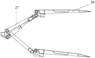
FIG. 5 is a schematic view of a movable bin door and a drive assembly of the multi-functional waste sorting cart according to an embodiment of the present application;
fig. 6 is a schematic view of a movable box door and a driving assembly of the multifunctional garbage sorting vehicle according to an embodiment of the present application.
Wherein: 100-multifunctional garbage classification vehicle, 1-chassis, 2-carriage, 21-garbage throwing area 21, 211-sealing component, 2111-upper cover, 2112-lower cover, 212-garbage throwing opening, 213-locking component, 22-cleaning area, 221-hand sink, 23-garbage can placing area, 24-switch component, 25-top cover, 26-movable box door, 27-driving component, 271-turning pressure cylinder, 272-direct-acting pressure cylinder and 3-cockpit.
Detailed Description
The technical solutions of the present invention will be described clearly and completely with reference to the accompanying drawings, and it should be understood that the described embodiments are some, but not all embodiments of the present invention. All other embodiments, which can be derived by a person skilled in the art from the embodiments given herein without making any creative effort, shall fall within the protection scope of the present invention.
In the description of the present invention, it should be noted that the terms "center", "upper", "lower", "left", "right", "vertical", "horizontal", "inner", "outer", etc., indicate orientations or positional relationships based on the orientations or positional relationships shown in the drawings, and are only for convenience of description and simplicity of description, but do not indicate or imply that the device or element being referred to must have a particular orientation, be constructed and operated in a particular orientation, and thus, should not be construed as limiting the present invention. Furthermore, the terms "first," "second," and "third" are used for descriptive purposes only and are not to be construed as indicating or implying relative importance.
In the description of the present invention, it should be noted that, unless otherwise explicitly specified or limited, the terms "mounted," "connected," and "connected" are to be construed broadly, e.g., as meaning either a fixed connection, a removable connection, or an integral connection; can be mechanically or electrically connected; they may be connected directly or indirectly through intervening media, or they may be interconnected between two elements. The specific meanings of the above terms in the present invention can be understood in specific cases to those skilled in the art.
In addition, the technical features involved in the different embodiments of the present invention described below may be combined with each other as long as they do not conflict with each other.
FIG. 1 is a left side view of a multi-functional waste sorting cart according to one embodiment of the present application; FIG. 2 is a right side view of the multi-functional waste sorting vehicle provided in one embodiment of the present application; FIG. 3 is a schematic view illustrating a top cover of the multi-functional garbage classification vehicle according to an embodiment of the present application in a pulled-out state; FIG. 4 is a schematic view illustrating a pushing state of a top cover of the multifunctional garbage sorting vehicle according to an embodiment of the present application; FIG. 5 is a schematic view of a movable bin door and a drive assembly of the multi-functional waste sorting cart according to an embodiment of the present application; fig. 6 is a schematic view of a movable box door and a driving assembly of the multifunctional garbage sorting vehicle according to an embodiment of the present application.
Referring to fig. 1 to 4, a preferred embodiment of the present application provides a multifunctional garbage sorting vehicle 100, wherein the garbage sorting vehicle 100 at least comprises: a chassis 1, and a cockpit 3 and a cabin 2 provided on the chassis 1. The chassis 1 serves as a load-bearing structural cab 3 for the refuse sorting vehicle 100. The driver operates in the cockpit 3, and then the subassembly makes the waste classification car 100 move to any place in district, and like this, the resident family in the district just need not to go to the garbage collection station specially again and pours rubbish, has made things convenient for resident family's life greatly, also alleviates sanitation staff's operating pressure simultaneously.
The carriage 2 is used as a garbage containing area, a garbage can containing area 23 is arranged inside the carriage and used for containing a large garbage can, and recoverable garbage is placed in the large garbage can. Because the large-scale garbage bin is too big, consequently, the loading and unloading degree of difficulty to large-scale garbage bin is very big. As shown in fig. 5 and 6, in order to facilitate loading and unloading of the large trash can, in one embodiment, the rear portion of the carriage 2 is provided with a movable box door 26 capable of at least partially closing the trash can placing area 23 and a driving assembly 27 for driving the movable box door 26 to rotate or move up and down horizontally, and the trash can is lifted up to the trash can placing area 23 by the movable box door 26 moving up and down horizontally or is transported to the ground by the trash can placing area 23.
Specifically, the driving unit 27 includes a group of tilting cylinders 271 for tilting the movable door 26 and a direct acting cylinder 272 for moving the movable door 26 up and down horizontally. The process of moving the large garbage can from the garbage can placing area 23 to the outside is as follows: firstly, the turnover pressure cylinder 271 drives the movable box door 26 to turn outwards until the movable box door 26 is parallel to the ground; then, the large trash can is pushed to the movable box door 26; then, the direct acting pressure cylinder 272 drives the movable box door 26 to move downwards until the movable box door 26 contacts with the movable box door; finally, the large trash can on the movable bin door 26 is removed. The process of moving the large garbage can from the outside to the garbage can placing area 23 is as follows: firstly, the large garbage can is moved to the movable box door 26; then, the direct acting type pressure cylinder 272 drives the movable box door 26 to move upwards until the movable box door 26 is parallel to the floor of the carriage 2; then, the turnover cylinder 271 drives the movable door 26 to turn inwards until the movable door 26 returns to the original position, and the large trash can slowly moves into the trash can placing area 23 during the process of turning the movable door 26 inwards.
Optionally, in order to ensure that the large trash can does not topple over due to shaking during moving, in one embodiment, the movable door 26 is further provided with a shielding member for fixing the large trash can.
The side of the carriage 2 near the door is provided with a switch assembly 24, and the switch assembly 24 comprises a start button for controlling the start of the driving assembly 27, a turnover button for controlling the motion of the turnover pressure cylinder and a horizontal button for controlling the motion of the direct-acting pressure cylinder. For ergonomic reasons, the switch assembly 24 is typically located on the side of the cabin 2 adjacent to the chassis 1. In this embodiment, the switch assembly 24 includes a toggle button in signal communication with the rotary cylinder and a level button in signal communication with the direct acting cylinder.
The carriage 2 is provided with a plurality of garbage throwing areas 21 for accommodating garbage of other different types in addition to a garbage can placing area 23 for placing recyclable garbage, and a plurality of garbage throwing openings 212 corresponding to the garbage throwing areas 21 are further formed in the side surface of the carriage 2. The garbage throwing area 21 comprises a harmful garbage throwing area and a kitchen garbage throwing area 21, the harmful garbage throwing area is used for throwing harmful garbage, and the kitchen garbage throwing area is used for throwing kitchen garbage. Because the quantity of harmful rubbish and rubbish from cooking is less for the quantity of other rubbish, consequently, the district volume setting is just also relatively less just for harmful rubbish is put in and is put in with rubbish from cooking, and the mirror image setting just is located the front end of carriage 2 in the both sides of carriage 2, so the design, can make full use of the inside space in carriage 2, make 2 inner spaces in carriage not extravagant.
The waste deposit area 21 comprises removable, insertable or replaceable waste bins (not shown) for placing different types of waste. If the garbage in the garbage bin is over-full, the garbage can may leak due to shaking during the transportation process of the vehicle. Therefore, in order to prevent the escape of the waste in the waste bin, the waste deposit area 21 comprises a closing member 211 closing the waste deposit opening 212. In one example, the closure assembly 211 includes a first rotational axis (not shown), a second rotational axis (not shown), an upper cap 2111 rotatable about the first rotational axis, and a lower cap 2112 rotatable about the second rotational axis. The upper lid 2111 has a function of closing the garbage input port 212 and can be opened to input garbage, and the lower lid 2112 has a function of closing the garbage input port 212 and can be opened to load and unload the garbage can.
Alternatively, the difference in the mounting positions of the first rotation shaft and the second rotation shaft may cause the upper cover 2111 and the lower cover 2112 to rotate in different manners, i.e., the upper cover 2111 and the lower cover 2112 are opened or closed in different manners. In one example, the first and second rotation shafts are disposed at upper and lower sides of the trash input port 212, so that the upper and lower covers 2111 and 2112 are turned upside down. Preferably, the upper lid 2111 is turned inwardly for depositing trash and the lower lid 2112 is turned outwardly for loading and unloading the trash. At this time, in order to conveniently throw the garbage, the upper cover 2111 does not need to be pushed by hand all the time, and in one embodiment, a clamping member (not shown) is further arranged in the garbage throwing area 21 for clamping the upper cover 2111, so that the upper cover 2111 cannot fall down when people throw the garbage. Of course, the upper cover 2111 and the lower cover 2112 may be turned inward or outward, and the present application is not limited thereto.
In another example, the first rotation shaft and the second rotation shaft are disposed at one side of the left and right sides of the trash input port 212 and are disposed up and down, and the first rotation shaft is disposed above the second rotation shaft, so that the upper cover 2111 and the lower cover 2112 are turned left and right. Preferably, the upper lid 2111 is flipped outwardly for depositing trash, and the lower lid 2112 is likewise flipped outwardly for loading and unloading the trash. Of course, the upper lid 2111 may be turned inward to deposit garbage, and the lower lid 2112 may be turned inward to load and unload the garbage can, which is not limited in this application.
In order to ensure the sealing property of the garbage throwing area 21 and improve the security between the sealing element and the garbage throwing opening 212, in one embodiment, a locking member 213 is further disposed on the garbage throwing area 21 for locking the sealing element 211 and the garbage throwing opening 212.
After the garbage is stored in the carriage 2, some garbage can be remained, and in the past, the garbage can be firmly adhered to the inner surface of the carriage 2 and is not easy to clean. Therefore, in this embodiment, the car 2 further includes a cleaning area 22, and the cleaning area 22 includes a high-pressure water gun (not shown) inside the car 2 and a high-pressure pump (not shown) for driving the high-pressure water gun to work, and the high-pressure water gun cooperates with the high-pressure pump to clean the inside of the car 2. Of course, in other examples, the cleaning member has at least one pair of wash-basin 221, a faucet, a water storage tank for storing clean water, a sewage collecting component for collecting sewage, and a drainage component for draining sewage, which are respectively disposed at two sides of the carriage 2, besides the high-pressure water gun for cleaning the interior of the carriage 2, the wash-basin is convenient for workers and garbage throwing personnel to clean themselves, the water storage tank can take water from the wash-basin to clean the interior of the carriage 2 and clean themselves without a water source, and the used sewage can be collected by the sewage collecting component and drained out of the vehicle through the drainage component.
In addition to the above structure, the vehicle body 2 further includes a roof 25, and the roof 25 can move horizontally back and forth with respect to the chassis 1 to keep out rain. As shown in fig. 3, when it is rainy or sunny, the top cover 25 can be pulled out for keeping out the rain or shading the sun. As shown in fig. 4, the top cover 25 can also be pushed inward, so that workers can stand in the carriage 2 when loading and unloading the trash can, and people can not stand normally due to the fact that the carriage 2 is too short.
The kitchen waste putting area in the kitchen waste putting area is too bad in smell when the kitchen waste is put in the kitchen waste putting area. In order to reduce the emission of the smell, in one embodiment, an exhaust fan is arranged at the top of the kitchen waste putting area and used for exchanging air inside and outside the kitchen waste putting area.
The toxic rubbish is put in the district because hold toxic rubbish, can produce the noxious material, consequently, in this embodiment, toxic rubbish is put in and is equipped with the disinfection subassembly in the district for disinfect in putting in the district to toxic rubbish.
In order to remind the residents and prevent the residents from being collided with by not seeing the garbage classification vehicle 100, in one embodiment, the garbage classification vehicle 100 further includes a buzzer which is located on the compartment 2 and is activated when the multi-functional garbage classification vehicle 100 travels.
In order to make the residents better understand the garbage classification vehicle 100, in one embodiment, each garbage throwing area is provided with a marker (not shown) for identifying the type of the garbage throwing area, and different garbage throwing areas correspond to different markers. Alternatively, the markers may be light reflecting stickers representing different types of trash, or the markers may be different colors.
In this embodiment, the overall size of the carriage 2 is small, so that the garbage sorting vehicle 100 can conveniently enter small residential areas, and can even stop at the door of a household, so that the household does not need to go to a garbage station to throw garbage, and the living convenience of the household is improved.
In order to facilitate the old or children to throw garbage, the height of the garbage throwing port 212 is not too high. Generally, the height of the trash input port 212 is set within a range in which the old or children can easily throw the trash. For example, the height of the garbage input port 212 is in the range of 0.8 to 1 m.
The beneficial effect of this application includes: the embodiment provides a flexible and convenient multifunctional garbage classification vehicle, and garbage can be classified while being collected by arranging a plurality of garbage throwing areas; by arranging the cleaning area, and the cleaning piece is arranged in the cleaning area, the interior of the garbage truck can be cleaned, and the cleanness of the garbage truck is ensured; through setting up drive assembly and being connected with the fly leaf, use mechanical structure to load and unload bulky rubbish, saved the manpower.
The technical features of the embodiments described above may be arbitrarily combined, and for the sake of brevity, all possible combinations of the technical features in the embodiments described above are not described, but should be considered as being within the scope of the present specification as long as there is no contradiction between the combinations of the technical features.
The above-mentioned embodiments only express several embodiments of the present application, and the description thereof is more specific and detailed, but not construed as limiting the scope of the present application. It should be noted that, for a person skilled in the art, several variations and modifications can be made without departing from the concept of the present application, which falls within the scope of protection of the present application. Therefore, the protection scope of the present patent shall be subject to the appended claims.
Claims (10)
1. The utility model provides a multi-functional waste classification car, its characterized in that, includes the chassis, and locates cockpit and carriage on the chassis, it places district, clean district and holds a plurality of rubbish of different grade type rubbish and puts in the district to be equipped with the garbage bin in the carriage, the carriage side is seted up with a plurality of rubbish that the district corresponds is put in to rubbish, clean district includes that at least one is a pair of locating respectively the wash-hand groove of carriage both sides, the carriage afterbody is equipped with but at least part seals the movable chamber door and the drive that the district was placed to the garbage bin movable chamber door rotates or horizontal motion's drive assembly from top to bottom, and the garbage bin is by horizontal motion from top to bottom the movable chamber door is raised extremely the garbage bin is placed the district or is placed by the garbage bin and is distinguished to ground.
2. The multi-functional waste classification vehicle of claim 1, characterized in that the waste deposit area comprises a toxic waste deposit area and a kitchen waste deposit area, and the toxic waste deposit area and the kitchen waste deposit area are arranged on both sides of the carriage in a mirror image manner.
3. The multifunctional garbage sorting vehicle of claim 2, wherein an exhaust fan is arranged at the top of the kitchen garbage throwing area, and the exhaust fan exchanges air between the inside and the outside of the kitchen garbage throwing area.
4. The multi-functional waste sorting vehicle of claim 2, wherein a sterilization assembly is provided in said toxic waste deposit area, said sterilization assembly sterilizing said toxic waste deposit area.
5. The multi-functional garbage classification vehicle as claimed in claim 1, wherein the driving assembly comprises a set of tilting cylinders for driving the door of the movable box to tilt and a set of direct-acting cylinders for driving the door of the movable box to move up and down horizontally.
6. The multi-functional garbage classification vehicle as claimed in claim 5, wherein a switch assembly is provided at a side of the carriage adjacent to the door, and the switch assembly comprises an activation button for controlling the activation of the driving assembly, a turnover button for controlling the movement of the turnover cylinder, and a horizontal button for controlling the movement of the direct-acting cylinder.
7. The multi-functional waste sorting vehicle of claim 1, wherein the carriage further comprises a top cover that is horizontally movable back and forth relative to the chassis, the top cover being movable in a direction toward the cab to enable a person to stand in the carriage, the top cover being movable in a direction away from the cab to block rain or shade from the sun.
8. The multi-functional garbage classification vehicle of claim 1, further comprising a buzzer, said buzzer being located on said carriage, said buzzer being activated when said multi-functional garbage classification vehicle travels.
9. The multi-functional waste sorting vehicle of claim 1, wherein each of said waste deposit areas is provided with a marker for identifying a type of said waste deposit area.
10. The multi-functional garbage classification vehicle as claimed in claim 1, wherein the clean area further comprises a high pressure water gun for cleaning the inside of the carriage, a water storage tank for storing clean water, a sewage collection assembly for collecting sewage, and a drainage assembly for draining the sewage.
Priority Applications (1)
| Application Number | Priority Date | Filing Date | Title |
|---|---|---|---|
| CN202121223400.0U CN214826236U (en) | 2021-06-02 | 2021-06-02 | Multifunctional garbage classification vehicle |
Applications Claiming Priority (1)
| Application Number | Priority Date | Filing Date | Title |
|---|---|---|---|
| CN202121223400.0U CN214826236U (en) | 2021-06-02 | 2021-06-02 | Multifunctional garbage classification vehicle |
Publications (1)
| Publication Number | Publication Date |
|---|---|
| CN214826236U true CN214826236U (en) | 2021-11-23 |
Family
ID=78800086
Family Applications (1)
| Application Number | Title | Priority Date | Filing Date |
|---|---|---|---|
| CN202121223400.0U Active CN214826236U (en) | 2021-06-02 | 2021-06-02 | Multifunctional garbage classification vehicle |
Country Status (1)
| Country | Link |
|---|---|
| CN (1) | CN214826236U (en) |
Cited By (1)
| Publication number | Priority date | Publication date | Assignee | Title |
|---|---|---|---|---|
| CN115321057A (en) * | 2022-09-16 | 2022-11-11 | 北京顺捷智诚环保科技有限公司 | Garbage transportation equipment |
-
2021
- 2021-06-02 CN CN202121223400.0U patent/CN214826236U/en active Active
Cited By (1)
| Publication number | Priority date | Publication date | Assignee | Title |
|---|---|---|---|---|
| CN115321057A (en) * | 2022-09-16 | 2022-11-11 | 北京顺捷智诚环保科技有限公司 | Garbage transportation equipment |
Similar Documents
| Publication | Publication Date | Title |
|---|---|---|
| US5181619A (en) | Apparatus and system for storing and collecting separated solid waste | |
| CN214826236U (en) | Multifunctional garbage classification vehicle | |
| WO2020087030A1 (en) | Trash storage and disposal system and method | |
| CN112407688A (en) | Automatically-opened municipal environment-friendly garbage collection system and use method thereof | |
| RU67557U1 (en) | WASTE DISCHARGE MODULE FOR SEPARATE WASTE COLLECTION | |
| CN110902219A (en) | Front-loading garbage feeding turnover mechanism and combined environmental sanitation equipment with same | |
| CN211253937U (en) | Garbage recovery vehicle | |
| CN216071527U (en) | Garbage classification vehicle | |
| CN213264002U (en) | Outdoor environmental protection classification dustbin of induction type | |
| CN211309676U (en) | Green solar energy garbage collection station with overflow alarm function | |
| CN208102965U (en) | A kind of detachable classifyed collecting dustbin | |
| CN208054163U (en) | A kind of construction site environment-friendly trash can convenient for toppling over | |
| CN214783538U (en) | Cleaning vehicle with garbage collection basket | |
| CN201080354Y (en) | Multifunctional dustbin storing and transporting vehicle | |
| CN211970504U (en) | Environment-friendly garbage can with protective structure | |
| CN213801341U (en) | Domestic garbage treatment device | |
| CN214030260U (en) | Double-barrel environment-friendly garbage recycling bin | |
| CN215324735U (en) | Can carry out automatic classification's rural rubbish environmental protection case to rubbish | |
| CN215754445U (en) | Multilayer garbage disposal box | |
| CN214268881U (en) | Intelligent garbage cabinet | |
| CN214650909U (en) | Energy-saving environment-friendly dustbin with deodorization function | |
| CN215247223U (en) | Multifunctional environment-friendly garbage can based on photovoltaic power generation | |
| CN214058748U (en) | Multifunctional environmental sanitation garbage truck | |
| CN112875079B (en) | Garbage classification box with disinfection function | |
| CN218908526U (en) | Garbage room convenient to put in and clear up |
Legal Events
| Date | Code | Title | Description |
|---|---|---|---|
| GR01 | Patent grant | ||
| GR01 | Patent grant |