CN214811031U - Electrolysis unit pallet convenient to quick installation is dismantled - Google Patents
Electrolysis unit pallet convenient to quick installation is dismantled Download PDFInfo
- Publication number
- CN214811031U CN214811031U CN202120265502.2U CN202120265502U CN214811031U CN 214811031 U CN214811031 U CN 214811031U CN 202120265502 U CN202120265502 U CN 202120265502U CN 214811031 U CN214811031 U CN 214811031U
- Authority
- CN
- China
- Prior art keywords
- rod
- limiting
- wall
- shaped
- fixedly arranged
- Prior art date
- Legal status (The legal status is an assumption and is not a legal conclusion. Google has not performed a legal analysis and makes no representation as to the accuracy of the status listed.)
- Active
Links
Images


Abstract
The utility model relates to the technical field of stands, and discloses an electrolysis device stand convenient for quick assembly and disassembly, which comprises a bottom plate, two supporting plates are symmetrically and fixedly arranged on the upper surface of the bottom plate, a bidirectional screw rod is arranged between the two supporting plates, the two end rod walls of the bidirectional screw rod are respectively and rotationally connected with the side walls of the corresponding supporting plates through first bearings, two sliders are symmetrically and threadedly connected to the rod walls at the two ends of the bidirectional screw rod, an L-shaped rod is fixedly arranged at the lower side of each slider, an L-shaped plate is rotatably connected to the lower end rod wall of each L-shaped rod through a second bearing, an electrolytic cell is arranged between the L-shaped plates in a clamped mode, a first limiting mechanism and a right limiting mechanism are fixedly arranged on the upper side wall of each slider, a through hole is formed in the rod wall of each L-shaped rod, and a second limiting mechanism is sleeved in the through hole in a movable mode. The utility model simplifies the disassembly and assembly process of the electrolytic cell, and is convenient for replacing different solutions for testing.
Description
Technical Field
The utility model relates to a pallet technical field especially relates to an electrolytic device pallet convenient to quick installation is dismantled.
Background
Electrolysis is the process of passing an electric current through an electrolyte solution or a molten electrolyte (electrolyte) to cause redox reactions at the cathode and anode, and may occur when a dc voltage is applied to an electrochemical cell.
The conventional electrolytic device stand is usually directly and fixedly installed on an electrolytic cell, so that the problem that the solution in the electrolytic cell is inconvenient to replace and clean when the solution needs to be replaced for an electrolytic test is caused.
SUMMERY OF THE UTILITY MODEL
The utility model aims at solving the problem that the solution inside the electrolytic cell is not convenient to replace in the prior art, and the problem of dismounting the electrolytic cell is not convenient when the solution is required to be replaced for testing, and providing an electrolytic device stand convenient for quick mounting and dismounting.
In order to achieve the above purpose, the utility model adopts the following technical scheme:
an electrolysis device stand convenient for quick assembly and disassembly comprises a bottom plate, two support plates are symmetrically and fixedly arranged on the upper surface of the bottom plate, a bidirectional screw rod is arranged between the two support plates, the two end rod walls of the bidirectional screw rod are respectively and rotationally connected with the side walls of the corresponding supporting plates through first bearings, two slide blocks are symmetrically and threadedly connected to the rod walls at the two ends of the bidirectional screw rod, L-shaped rods are fixedly arranged at the lower sides of the two slide blocks respectively, the lower end rod walls of the two L-shaped rods are rotatably connected with L-shaped plates through second bearings respectively, an electrolytic bath is clamped between the two L-shaped plates, a first limiting mechanism is fixedly arranged on the upper side wall of each slide block, a through hole is formed in the rod wall of the L-shaped rod at the right side, a second limiting mechanism is movably sleeved inside the through hole, and a waste liquid groove is formed in the upper surface of the bottom plate.
Preferably, first stop gear includes first gag lever post and two first stoppers, two first stopper is fixed respectively and sets up in the last lateral wall of the slider that corresponds, two spacing hole has all been seted up to the inside of first stopper, the pole wall of first gag lever post is common and two spacing hole between the activity cup joint, the both ends of first gag lever post respectively with the backup pad fixed connection that corresponds.
Preferably, the second stop gear includes second stopper and second gag lever post, the pole wall of second gag lever post cup joints with the inner wall activity of through-hole, the right side two slots have been seted up to the right side wall symmetry of L shaped plate, the activity is pegged graft between the left end pole wall of second gag lever post and the slot that corresponds, the left end pole wall of second stopper and second gag lever post is fixed to be cup jointed, the fixed piece that draws that is provided with of right-hand member of second gag lever post.
Preferably, the right end of the bidirectional screw rod penetrates through the right supporting plate and is fixedly connected with a knob.
Preferably, the rod wall of the second limiting rod is movably sleeved with a spring, and two ends of the spring are fixedly connected with the second limiting block and the L-shaped plate on the right side respectively.
Preferably, the two sides of the bottom plate are symmetrically and fixedly provided with mounting blocks, and fastening bolts are fixedly arranged in the mounting blocks.
Compared with the prior art, the utility model provides an electrolytic device pallet convenient to quick installation is dismantled possesses following beneficial effect:
1. this electrolytic device pallet convenient to quick installation is dismantled through the first stop gear who is equipped with, can drive two slider movements when rotating the lead screw through the knob to realize that two L shaped plates carry out the joint, the normal use of the electrolysis trough of being convenient for to the electrolysis trough.
2. This electrolytic device pallet convenient to quick installation is dismantled through setting up in the inside second stop gear of the through-hole of right side L shape pole, when can need changing the inside solution of electrolysis trough, through removing the rotation that realizes two L shaped plates behind second stop gear's the limiting displacement to be convenient for take out the waste liquid.
The part not involved in the device is the same as the prior art or can be realized by adopting the prior art, the utility model simplifies the disassembly and assembly process of the electrolytic cell, and is convenient for replacing different solutions for testing.
Drawings
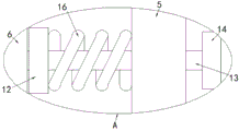
FIG. 1 is a schematic structural view of an electrolyzer support convenient for quick assembly and disassembly according to the present invention;
fig. 2 is a schematic view of a top-down connection structure of two sliding blocks and a first limiting mechanism in an electrolysis device stand convenient for quick assembly and disassembly according to the present invention;
fig. 3 is an enlarged view of a portion a of fig. 2.
In the figure: the device comprises a base plate 1, a support plate 2, a bidirectional screw rod 3, a sliding block 4, a 5L-shaped rod, a 6L-shaped plate, an electrolytic tank 7, an installation block 8, a waste liquid tank 9, a first limiting rod 10, a first limiting block 11, a second limiting block 12, a second limiting rod 13, a pull block 14, a knob 15 and a spring 16.
Detailed Description
The technical solutions in the embodiments of the present invention will be described clearly and completely with reference to the accompanying drawings in the embodiments of the present invention, and it is obvious that the described embodiments are only some embodiments of the present invention, not all embodiments.
In the description of the present invention, it is to be understood that the terms "upper", "lower", "front", "rear", "left", "right", "top", "bottom", "inner", "outer", and the like indicate orientations or positional relationships based on the orientations or positional relationships shown in the drawings, and are only for convenience of description and simplicity of description, and do not indicate or imply that the device or element being referred to must have a particular orientation, be constructed and operated in a particular orientation, and therefore, should not be construed as limiting the present invention.
Referring to fig. 1-2, an electrolysis apparatus stand convenient for quick assembly and disassembly comprises a bottom plate 1, wherein two support plates 2 are symmetrically and fixedly arranged on the upper surface of the bottom plate 1, a bidirectional screw rod 3 is arranged between the two support plates 2, two end rod walls of the bidirectional screw rod 3 are respectively rotatably connected with the side walls of the corresponding support plates 2 through first bearings, two sliders 4 are symmetrically and threadedly connected with the two end rod walls of the bidirectional screw rod 3, L-shaped rods 5 are respectively and fixedly arranged on the lower sides of the two sliders 4, the lower end rod walls of the two L-shaped rods 5 are respectively and rotatably connected with L-shaped plates 6 through second bearings, an electrolysis bath 7 is clamped between the two L-shaped plates 6, a first limiting mechanism is fixedly arranged on the upper side walls of the two sliders 4, a through hole is formed in the rod wall of the L-shaped rod 5 on the right side, and a second limiting mechanism is movably sleeved in the through hole, the upper surface of the bottom plate 1 is provided with a waste liquid tank 9.
First stop gear includes first gag lever post 10 and two first stopper 11, two first stopper 11 is fixed respectively and sets up in the last lateral wall of the slider 4 that corresponds, two spacing hole has all been seted up to first stopper 11's inside, the pole wall of first gag lever post 10 is common and the activity cup joints between two spacing holes, the both ends of first gag lever post 10 respectively with 2 fixed connection of backup pad that correspond.
The second stop gear includes second stopper 12 and second gag lever post 13, the pole wall of second gag lever post 13 cup joints with the inner wall activity of through-hole, the right side two slots have been seted up to the right side wall symmetry of L shaped plate 6, the activity is pegged graft between the left end pole wall of second gag lever post 13 and the slot that corresponds, second stopper 12 cup joints with the left end pole wall of second gag lever post 13 is fixed, the fixed piece 14 that draws that is provided with of right-hand member of second gag lever post 13 is convenient for drive the motion of second gag lever post 13 through drawing piece 14.
The right end of the bidirectional screw rod 3 penetrates through the supporting plate 2 on the right side and is fixedly connected with a knob 15, and the screw rod is driven to rotate conveniently through the knob 15.
The spring 16 is movably sleeved on the rod wall of the second limiting rod 13, and two ends of the spring 16 are fixedly connected with the second limiting block 12 and the L-shaped plate 6 on the right side respectively, so that the second limiting rod 13 can be inserted into the corresponding slot when no external force exists.
The both sides symmetry of bottom plate 1 is fixed and is provided with installation piece 8, every installation piece 8's inside all is fixed and is provided with fastening bolt, is convenient for firmly install whole device.
The utility model discloses in, during the use, if need carry out the dismouting to electrolysis trough 7, rotate knob 15, knob 15 drives two-way lead screw 3 and rotates, lead screw pivoted is simultaneously cup jointed through the activity between two first stoppers 11 and the first gag lever post 10 and is driven two sliders 4 simultaneous motions, two sliders 4 drive the motion of corresponding L shape pole 5 respectively, two L shape poles 5 drive the motion of corresponding L shaped plate 6 respectively, thereby be convenient for carry out quick assembly disassembly to electrolysis trough 7, when needing to change the electrolytic solution, the pulling draws piece 14, draw piece 14 to drive second gag lever post 13 and shift out from the inside of the slot that corresponds, thereby be convenient for rotate two L shaped plates 6, and then be convenient for take out the inside waste liquid of electrolysis trough 7.
The above, only be the concrete implementation of the preferred embodiment of the present invention, but the protection scope of the present invention is not limited thereto, and any person skilled in the art is in the technical scope of the present invention, according to the technical solution of the present invention and the utility model, the concept of which is equivalent to replace or change, should be covered within the protection scope of the present invention.
Claims (6)
1. An electrolysis device stand convenient to quickly mount and dismount comprises a bottom plate (1) and is characterized in that two support plates (2) are symmetrically and fixedly arranged on the upper surface of the bottom plate (1), a two-way lead screw (3) is arranged between the two support plates (2), rod walls at two ends of the two-way lead screw (3) are respectively and rotatably connected with the side walls of the corresponding support plates (2) through first bearings, the rod walls at two ends of the two-way lead screw (3) are symmetrically and threadedly connected with two sliding blocks (4), L-shaped rods (5) are respectively and fixedly arranged at the lower sides of the two sliding blocks (4), L-shaped plates (6) are respectively and rotatably connected with lower end rod walls of the two L-shaped rods (5) through second bearings, an electrolysis bath (7) is arranged between the two L-shaped plates (6) in a clamping manner, and a first limiting mechanism is fixedly arranged on the upper side walls of the two sliding blocks (4), a through hole is formed in the rod wall of the L-shaped rod (5) on the right side, a second limiting mechanism is movably sleeved in the through hole, and a waste liquid groove (9) is formed in the upper surface of the bottom plate (1).
2. The electrolytic device stand convenient to install and detach rapidly as claimed in claim 1, wherein the first limiting mechanism comprises a first limiting rod (10) and two first limiting blocks (11), the two first limiting blocks (11) are respectively and fixedly arranged on the upper side wall of the corresponding sliding block (4), the two limiting holes are formed in the inner portion of each first limiting block (11), the rod wall of each first limiting rod (10) is movably sleeved between the two limiting holes, and two ends of each first limiting rod (10) are respectively and fixedly connected with the corresponding supporting plate (2).
3. The electrolyzer stand convenient for quick installation and disassembly as claimed in claim 1, wherein the second limiting mechanism comprises a second limiting block (12) and a second limiting rod (13), the rod wall of the second limiting rod (13) is movably sleeved with the inner wall of the through hole, the right side of the right side wall of the L-shaped plate (6) is symmetrically provided with two slots, the left end rod wall of the second limiting rod (13) is movably inserted into the corresponding slots, the second limiting block (12) is fixedly sleeved with the left end rod wall of the second limiting rod (13), and the right end of the second limiting rod (13) is fixedly provided with a pull block (14).
4. The electrolyzer stand convenient for quick assembly and disassembly according to claim 1 characterized in that the right end of the bidirectional screw rod (3) penetrates the right support plate (2) and is fixedly connected with a knob (15).
5. The electrolysis unit stand convenient to install and disassemble quickly as claimed in claim 3, wherein the rod wall of the second limiting rod (13) is movably sleeved with a spring (16), and two ends of the spring (16) are respectively and fixedly connected with the second limiting rod (12) and the L-shaped plate (6) on the right side.
6. The electrolyzer stand convenient for quick assembly and disassembly according to claim 1 characterized in that the bottom plate (1) is symmetrically and fixedly provided with mounting blocks (8) at both sides, and fastening bolts are fixedly arranged inside each mounting block (8).
Priority Applications (1)
| Application Number | Priority Date | Filing Date | Title |
|---|---|---|---|
| CN202120265502.2U CN214811031U (en) | 2021-01-31 | 2021-01-31 | Electrolysis unit pallet convenient to quick installation is dismantled |
Applications Claiming Priority (1)
| Application Number | Priority Date | Filing Date | Title |
|---|---|---|---|
| CN202120265502.2U CN214811031U (en) | 2021-01-31 | 2021-01-31 | Electrolysis unit pallet convenient to quick installation is dismantled |
Publications (1)
| Publication Number | Publication Date |
|---|---|
| CN214811031U true CN214811031U (en) | 2021-11-23 |
Family
ID=78954084
Family Applications (1)
| Application Number | Title | Priority Date | Filing Date |
|---|---|---|---|
| CN202120265502.2U Active CN214811031U (en) | 2021-01-31 | 2021-01-31 | Electrolysis unit pallet convenient to quick installation is dismantled |
Country Status (1)
| Country | Link |
|---|---|
| CN (1) | CN214811031U (en) |
-
2021
- 2021-01-31 CN CN202120265502.2U patent/CN214811031U/en active Active
Similar Documents
| Publication | Publication Date | Title |
|---|---|---|
| CN214811031U (en) | Electrolysis unit pallet convenient to quick installation is dismantled | |
| CN210939040U (en) | Shell installation equipment for production and processing of instruments and meters | |
| CN210060258U (en) | Welding tool for automobile seat framework | |
| CN215481331U (en) | Copper equipment is carried in etching waste liquid electrolysis | |
| CN214736166U (en) | Hardware surface treatment device with good positioning effect | |
| CN215510487U (en) | Electrolytic copper high accuracy mirror surface burnishing device | |
| CN215828883U (en) | A lift diaphragm electrolysis recovery unit for noble metal draws production | |
| CN215628337U (en) | Cleaning device of electrolytic cell | |
| CN108486640A (en) | A kind of electronic product plating device | |
| CN111364078B (en) | Omnibearing suspension electroplating method and electroplating equipment | |
| CN209816304U (en) | Full-automatic annular hardware and plastic double-cathode electroplating equipment | |
| CN211423736U (en) | Attendance device with multiple mounting means | |
| CN211840408U (en) | Quick cutting device of electrolysis copper | |
| CN218880082U (en) | Electrolytic bath | |
| CN219621280U (en) | Cell-phone center positive pole tool | |
| CN209685925U (en) | A kind of electrolytic aluminium anode installation positioning device | |
| CN217869102U (en) | Electrolytic separation tank for nitrogen generator | |
| CN112647113A (en) | Hanging mechanism, workpiece processing device and workpiece processing system | |
| CN211555072U (en) | Portable security device of community security protection | |
| CN218580117U (en) | Electroplating flying bar convenient to use | |
| CN108642526A (en) | A kind of electrolytic aluminium anode installation positioning device | |
| CN220413585U (en) | Circuit board electroplating floating plate | |
| CN212051712U (en) | Cathode structure capable of shaking for electroplating | |
| CN214445670U (en) | Automobile part overturning tool | |
| CN218397808U (en) | Electromechanical maintenance positioning and clamping device |
Legal Events
| Date | Code | Title | Description |
|---|---|---|---|
| GR01 | Patent grant | ||
| GR01 | Patent grant |