CN214804231U - Steam barbecue oven using biomass particles - Google Patents
Steam barbecue oven using biomass particles Download PDFInfo
- Publication number
- CN214804231U CN214804231U CN202120368507.8U CN202120368507U CN214804231U CN 214804231 U CN214804231 U CN 214804231U CN 202120368507 U CN202120368507 U CN 202120368507U CN 214804231 U CN214804231 U CN 214804231U
- Authority
- CN
- China
- Prior art keywords
- barbecue
- steam
- combustion chamber
- hopper
- oven
- Prior art date
- Legal status (The legal status is an assumption and is not a legal conclusion. Google has not performed a legal analysis and makes no representation as to the accuracy of the status listed.)
- Active
Links
Images


Classifications
-
- Y—GENERAL TAGGING OF NEW TECHNOLOGICAL DEVELOPMENTS; GENERAL TAGGING OF CROSS-SECTIONAL TECHNOLOGIES SPANNING OVER SEVERAL SECTIONS OF THE IPC; TECHNICAL SUBJECTS COVERED BY FORMER USPC CROSS-REFERENCE ART COLLECTIONS [XRACs] AND DIGESTS
- Y02—TECHNOLOGIES OR APPLICATIONS FOR MITIGATION OR ADAPTATION AGAINST CLIMATE CHANGE
- Y02A—TECHNOLOGIES FOR ADAPTATION TO CLIMATE CHANGE
- Y02A40/00—Adaptation technologies in agriculture, forestry, livestock or agroalimentary production
- Y02A40/90—Adaptation technologies in agriculture, forestry, livestock or agroalimentary production in food processing or handling, e.g. food conservation
- Y02A40/924—Adaptation technologies in agriculture, forestry, livestock or agroalimentary production in food processing or handling, e.g. food conservation using renewable energies
- Y02A40/928—Cooking stoves using biomass
Abstract
The utility model discloses a steam barbecue stove of living beings granule, include: a barbecue grill is arranged inside the barbecue oven; the fuel tank is arranged at one end of the barbecue box, a hopper and a steam system are arranged in the fuel tank, and the hopper is used for storing biomass granular fuel and supplying the biomass granular fuel to the barbecue box; the steam system comprises a steam pipe, and the steam pipe penetrates through the barbecue oven to input steam into the barbecue oven; the bar-shaped box is partially arranged in the barbecue box in a penetrating way; the bar case both ends are equipped with feed inlet and combustion chamber respectively, and the hopper below is located to the feed inlet, and the barbecue below is located to the combustion chamber, and the bar incasement is equipped with transmission device in order to carry the fuel that gets into to the combustion chamber from the feed inlet. According to the utility model discloses use steam oven of living beings granule can be at the in-process of food barbecue toward barbecue incasement input steam, and the food of roast out is burnt tender in the outer, has promoted the food taste of roast out.
Description
Technical Field
The utility model relates to a barbecue oven, in particular to a steam barbecue oven using biomass particles.
Background
Many people like outdoor barbecue activities, so outdoor barbecue ovens are also increasingly popular with the public. Most granule oven appearances on the market are simple, and the function is few, and most living beings granule oven is open air barbecue moreover, and food is because moisture is baked dry rapidly in the oven, leads to food to roast burnt, roast to be burnt very easily, influences the taste of the food of roast out.
SUMMERY OF THE UTILITY MODEL
The utility model discloses aim at solving one of the technical problem that exists among the prior art at least. Therefore, the utility model provides an use steam oven of living beings granule has increased steam system on current oven basis, toward barbecue incasement input steam for food still has the effect of being evaporated simultaneously at the in-process of being roasted, and the food of roast out is burnt tender in the outsider, has promoted food taste.
According to the utility model discloses a steam oven of using living beings granule of first aspect embodiment includes: a barbecue grill is arranged inside the barbecue oven; the fuel tank is arranged at one end of the barbecue box, a hopper and a steam system are arranged in the fuel tank, and the hopper is used for storing biomass granular fuel and supplying the biomass granular fuel to the barbecue box; the steam system comprises a steam pipe, and the steam pipe penetrates through the barbecue oven and inputs steam into the barbecue oven; the bar-shaped box is partially arranged in the barbecue box in a penetrating way; the barbecue grill is characterized in that a feed port and a combustion chamber are respectively arranged at two ends of the strip-shaped box, the feed port is arranged below the hopper, the combustion chamber is arranged below the barbecue grill, and a transmission device is arranged in the strip-shaped box to convey fuel entering from the feed port to the combustion chamber.
According to the utility model discloses use steam oven of living beings granule has following beneficial effect at least: the utility model discloses a steam oven inputs steam toward the barbecue incasement at the in-process of food barbecue for food is being compared the outdoor oven that most used charcoal fire at present at the in-process of barbecue equally having the effect of evaporating, even do not have the barbecue experience and also can not be easy with food scorching, roast and stick with paste, and the food of roast out is burnt tender in the outer, has effectively promoted the food taste of roast out.
According to some embodiments of the invention, the steam system comprises a water tank, a water pump and a steam generator, the water pump drawing water from the water tank and pumping to the steam generator, the steam generator atomizing water into steam and providing to the steam pipe.
According to some embodiments of the utility model, be equipped with the box container in the fuel tank, box container one end is equipped with the opening and the open end extends the fuel tank, water tank slidable mounting in the box container.
According to some embodiments of the invention, the other end of the box container is provided with a connecting tube; one end of the water tank is provided with a water outlet pipe, the other end of the water tank is connected with a supporting plate, the water outlet pipe is embedded into the connecting pipe, and the supporting plate is abutted to the opening end of the tank container.
According to some embodiments of the present invention, two slots are disposed at an interval on an end surface of the water tank away from the water outlet pipe, and a spacing support pillar is disposed between the two slots; one side of the abutting plate, facing the water tank, is provided with an embedded plate matched with the slot, and an elastic sheet is arranged between the two embedded plates; the opening of the slot faces upwards, the embedded plate is inserted into the slot, and the elastic piece abuts against the bottom of the limiting abutting column.
According to the utility model discloses a some embodiments, the hopper bottom is equipped with discharge gate and open closed clean mouthful, the discharge gate with the feed inlet intercommunication, clean mouthful intercommunication atmosphere.
According to the utility model discloses a some embodiments, transmission device is the transfer screw, the transfer screw is located the bar incasement, the transfer screw is connected with and drives its drive arrangement around self axis rotation, the transfer screw can be followed with fuel when rotatory in the feed inlet is carried to the combustion chamber.
According to the utility model discloses a few embodiments, the bar incasement is equipped with the conveying pipeline, conveying screw locates in the conveying pipeline, conveying pipeline one end periphery wall be equipped with the material hole with the feed inlet intercommunication, the other end with the combustion chamber intercommunication.
According to some embodiments of the utility model, the bar case still is equipped with the air intake, the air intake with the feed inlet sets up relatively, the air intake bottom be equipped with the fan be used for to bar incasement blast air.
According to some embodiments of the present invention, a heat insulation member, a heat distribution cover and an oil receiving tray are further disposed in the barbecue oven, the oil receiving tray is disposed below the barbecue grill, and two ends of the oil receiving tray are respectively connected to end walls at two ends of the barbecue grill; the heat distribution cover is arranged below the oil receiving disc, the heat insulation piece is arranged below the heat distribution cover, and the heat insulation piece is connected with the barbecue box and covers the combustion chamber.
Additional aspects and advantages of the invention will be set forth in part in the description which follows and, in part, will be obvious from the description, or may be learned by practice of the invention.
Drawings
The above and/or additional aspects and advantages of the present invention will become apparent and readily appreciated from the following description of the embodiments, taken in conjunction with the accompanying drawings of which:
fig. 1 is a schematic structural diagram of an embodiment of the present invention;
fig. 2 is an exploded view of an embodiment of the present invention;
FIG. 3 is a schematic view of the internal structure of the fuel tank of the present invention;
FIG. 4 is an exploded view of the water tank of the present invention;
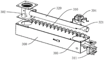
FIG. 5 is a schematic view of the structure of the fuel tank and the strip tank of the present invention;
FIG. 6 is an exploded view of the strip-shaped case of the present invention;
fig. 7 is a schematic structural view of the hopper of the present invention;
fig. 8 is a schematic structural view of the shelf of the present invention;
figure 9 is a cross-sectional view of an embodiment of the invention;
fig. 10 is an enlarged view at a in fig. 7.
Reference numerals:
the barbecue grill comprises a barbecue case 100, a barbecue grill 101, a case cover 102, a chimney 103, a positioning bolt 104, a shelf 110, a side plate 111, a drawing plate 112, a hanging plate 113, a limiting hole 114, a U-shaped groove 115, a front plate 120, a connecting plate 130, a dust barrel 131, a heat insulation piece 140, a short side plate 141, a positioning protrusion 142, a heat distribution cover 150, a long side plate 151, a positioning groove 152, an oil receiving disc 160, an oil receiving box 161, an oil draining groove 162, an oil receiving support 170, an oil barrel 171 and a storage cabinet 180.
The water tank comprises a fuel tank 200, a heat insulation plate 201, a hopper 210, a discharge hole 211, a cleaning hole 212, a filter screen 213, a hopper cover 214, an observation hole 215, a cover plate 220, a digging plate 221, a limiting groove 222, a limiting plate 230, a limiting bolt 231, a water tank 240, a water outlet pipe 241, an insertion groove 242, a limiting support column 243, a water pump 250, a steam generator 260, a steam pipe 261, a tank container 270, a connecting pipe 271, a support plate 280, an embedded plate 281 and an elastic sheet 282;
the device comprises a strip-shaped box 300, a feed inlet 301, a combustion chamber 302, an air inlet 303, a fan 304, a conveying screw 310, a driving motor 311, a conveying pipeline 320 and a material hole 321.
Detailed Description
Reference will now be made in detail to embodiments of the present invention, examples of which are illustrated in the accompanying drawings, wherein like reference numerals refer to the same or similar elements or elements having the same or similar function throughout. The embodiments described below with reference to the drawings are exemplary only for the purpose of explaining the present invention, and should not be construed as limiting the present invention.
In the description of the present invention, it is to be understood that the terms "center", "longitudinal", "lateral", "length", "width", "thickness", "upper", "lower", "front", "rear", "left", "right", "vertical", "horizontal", "top", "bottom", "inner", "outer", "axial", "radial", "circumferential", and the like indicate orientations or positional relationships based on those shown in the drawings, and are only for convenience of description and simplicity of description, and do not indicate or imply that the device or element referred to must have a particular orientation, be constructed and operated in a particular orientation, and therefore should not be construed as limiting the present invention. Furthermore, a feature defined as "first" or "second" may explicitly or implicitly include one or more of that feature. In the description of the present invention, "a plurality" means two or more unless otherwise specified.
In the description of the present invention, it is to be noted that, unless otherwise explicitly specified or limited, the terms "mounted," "connected," and "connected" are to be construed broadly, and may be, for example, fixedly connected, detachably connected, or integrally connected; can be mechanically or electrically connected; they may be connected directly or indirectly through intervening media, or they may be interconnected between two elements. The specific meaning of the above terms in the present invention can be understood in specific cases to those skilled in the art.
Referring to fig. 1 to 10, a steam barbecue grill using biomass particles according to an embodiment of the present invention includes: a barbecue cabinet 100 having a grill 101 therein; the bottom of the grill 101 is provided with a storage cabinet 180, and the barbecue oven 100 is mounted on the storage cabinet 180. The rollers are arranged at the bottom of the storage cabinet 180 to facilitate outdoor movement, the barbecue oven 100 is in a hollow cylindrical shape, the top of the storage cabinet 180 is provided with a semicircular groove with the same shape as the peripheral wall of the barbecue oven 100, and the barbecue oven 100 is embedded into the semicircular groove at the top of the storage cabinet 180, namely, half of the space of the barbecue oven 100 is embedded into the storage cabinet 180, so that the space occupation is saved. The barbecue oven 100 comprises a barbecue grill 101 and a oven cover 102, wherein the barbecue grill 101 is provided with two layers, and the two layers of barbecue grills 101 are arranged in the barbecue oven 100 at intervals up and down; a cover 102 is hingedly attached to the outer peripheral wall of the barbecue cabinet 100 and can be opened to one side to facilitate handling of food on the grill 101. The lid 102 is a quarter circle, the hinge of the lid 102 to the grill 100 is the top of the grill 100, and when the lid 102 is opened, a quarter of the grill 101 is opened, and the grill 101 is exposed to cook food. A thermometer is also provided on the lid 102 for monitoring the temperature within the barbecue cabinet 100. The grill 101 has two layers, both horizontally disposed, with the upper layer having a smaller area than the bottom layer.
A fuel tank 200 provided at one end of the barbecue cabinet 100, wherein a hopper 210 and a steam system are provided in the fuel tank 200, and the hopper 210 is used for storing biomass granular fuel and providing the biomass granular fuel to the barbecue cabinet 100; the steam system includes a steam pipe 261, and the steam pipe 261 inputs steam into the barbecue cabinet 100 through the barbecue cabinet 100. The top of the hopper 210 is provided with a filter screen 213, a cover 214 is arranged above the filter screen 213, and the cover 214 is hinged with the hopper 210 and used for sealing the top of the hopper 210. As shown in fig. 2, the cover 214 is hinged to one side of the hopper 210 close to the strip-shaped box 300, and the cover 214 can rotate around the hinge, so that the cover 214 can be opened towards one side; the screen 213 is inserted into the hopper 210, and an inner wall of an upper portion of the hopper 210 is provided with an inwardly protruding flange for supporting the screen 213. When the biomass particle fuel is fed into the hopper 210, the biomass particle fuel is primarily filtered by the filter screen 213, so that the biomass particle fuel entering the hopper 210 cannot block the discharge hole 211 or cannot enter the conveying device due to overlarge particles. The wall of the hopper 210 on one side is further provided with an observation hole 215, and transparent glass is arranged on the observation hole 215, so that the amount of fuel in the hopper 210 can be seen from the outside through the observation hole 215, and the fuel can be added conveniently.
A bar-shaped box 300 partially penetrating the barbecue oven 100; the two ends of the bar-shaped box 300 are respectively provided with a feed inlet 301 and a combustion chamber 302, the feed inlet 301 is arranged below the hopper 210, the combustion chamber 302 is arranged below the barbecue grill 101, and a transmission device is arranged in the bar-shaped box 300 to convey fuel entering from the feed inlet 301 to the combustion chamber 302. Most of the existing barbecue ovens are open-air barbecue ovens, charcoal fire is used for barbecue below the oven, food is easily burnt and burnt without barbecue experience, and the food is easily scalded; the common biomass particle oven also has the problems of easy food scorching and burning; the utility model discloses a steam oven inputs steam toward barbecue case 100 at the in-process of food barbecue for food has the effect of evaporating equally at the in-process of being barbecue, and the food of roast out is burnt tender in the outer, has effectively promoted the food taste of roast out.
In some embodiments of the present invention, the steam system includes a water tank 240, a water pump 250, and a steam generator 260, the water pump 250 drawing water from the water tank 240 and pumping to the steam generator 260, the steam generator 260 atomizing and providing the water to a steam pipe 261. Specifically, as shown in fig. 3, the water tank 240, the water pump 250 and the steam generator 260 are disposed in the fuel tank 200, the water pump 250 and the steam generator 260 are commercially available devices, and the steam pipe 261 is communicated to the interior of the barbecue cabinet 100 and to the middle of the double-layered barbecue grill 101. A level alarm is provided in the tank 240 to give an alarm when the level is below a set value. The utility model discloses a steam system and transmission device etc. all control through automatically controlled board. During the use, the power is started, the barbecue use temperature is set, the barbecue mode is entered, after barbecue for 10-15 minutes, the steam system starts to start under the control of the electric control board, the water pump 250 starts to pump water into the steam generator 260, the steam generator 260 starts to work, and after 50 seconds, steam enters the barbecue oven 100 through the steam pipe 261. And after working for 30-50 seconds, stopping inputting steam. And working in a cycle of about 6-8 minutes until the food is cooked.
In some embodiments of the present invention, a box container 270 with an opening at one end is disposed in the fuel tank 200, the opening is disposed at one end of the box container 270, the opening end extends out of the fuel tank 200, and the water tank 240 is slidably mounted in the box container 270. Specifically, as shown in fig. 4, an opening is formed at the front end of the tank container 270, a rim protruding outward is formed at the opening end, a square hole having a shape identical to that of a section of the tank container 270 is formed in the wall of the fuel tank 200 on the front side of the tank container 270, the tank container 270 is inserted into the square hole, and the rim of the opening end of the tank container 270 abuts against the outer surface of the fuel tank 200. The other end of the tank container 270 away from the open end is connected with a support, the support is fixedly connected with the bottom of the fuel tank 200, and one end of the tank container 270 away from the open end is provided with a protruding part which is movably arranged on the support in a penetrating way and can slide relative to the support. The front end and the rear end of the box container 270 are respectively supported by the bracket and the square hole.
In some embodiments of the present invention, the other end of the box container 270 is provided with a connecting pipe 271; one end of the water tank 240 is provided with a water outlet pipe 241, the other end is connected with a resisting plate 280, the water outlet pipe 241 is embedded into the connecting pipe 271, and the resisting plate 280 is propped against the end surface of the tank body container 270. Specifically, the connection pipe 271 is connected to the water pump 250, the water outlet pipe 241 is connected to the bottom of the water tank 240, and the water outlet pipe 241 can be inserted into the connection pipe 271, so that the water pump 250 pumps water from the water tank 240. The outer peripheral wall of the part of the water outlet pipe 241 inserted into the connecting pipe 271 is provided with a silica gel sleeve which plays a role in increasing friction and sealing; when the water tank 240 is pushed inwards to a position abutting against the tank body container 270, the water outlet pipe 241 is inserted into the connecting pipe 271, the silica gel sleeve is contacted with the inner wall of the connecting pipe 271, a sealing effect is achieved in the water pumping process of the water pump 250, and water in the water outlet pipe 241 is prevented from flowing into the tank body container 270; and meanwhile, the friction force between the connecting pipe 271 and the water outlet pipe 241 is increased, and the water tank 240 is prevented from sliding out of the open end of the tank container 270.
In a further embodiment of the present invention, two slots 242 are disposed at an interval on an end surface of the water tank 240 away from the water outlet pipe 241, and a limiting prop 243 is disposed between the two slots 242; an embedded plate 281 matched with the slot 242 is arranged on one side of the abutting plate 280 facing the water tank 240, and an elastic sheet 282 is arranged between the two embedded plates 281; the slot 242 has an opening facing upward and the insertion plate 281 is inserted into the slot 242, and the elastic piece 282 abuts against the bottom of the limiting abutting column 243 to prevent the insertion plate 281 from being pulled out upward. Specifically, as shown in fig. 4, the slot 242 is a through slot, the insertion plate 281 is vertically inserted into the slot 242 downward, when the insertion plate 281 is inserted into the slot 242 downward, the outer wall of the elastic piece 282 abuts against the limit abutment 243, during the downward movement of the insertion plate 281, the elastic piece 282 is elastically deformed, and after the insertion plate 281 is inserted into place downward, the elastic piece 282 recovers its original shape and is inserted into the bottom of the limit abutment 243, thereby preventing the abutment 280 from being drawn out upward.
It should be noted that the area of the abutting plate 280 is larger than the area of the opening end of the case container 270, and thus. After water tank 240 is inserted into tank container 270, retaining plate 280 can seal the open end of tank container 270.
In some embodiments of the present invention, the bottom of the hopper 210 is provided with a discharge port 211 and an openable and closable cleaning port 212, the discharge port 211 is communicated with the feed port 301, and the cleaning port 212 is communicated with the atmosphere. The discharge port 211 and the cleaning port 212 are arranged at an interval, an arc-shaped channel is arranged at the bottom of the cleaning port 212, and the arc-shaped channel is communicated with the atmosphere on one side of the hopper 210 so as to discharge the fuel in the hopper 210 from one side of the hopper 210. Debris is generated during the storage and transportation process of the biomass particles, particularly in the storage hopper 210, and a large amount of debris is easily accumulated at the bottom of the storage hopper for long-term use, so that the transportation of the biomass particles is affected; and when the storage hopper 210 is full of fuel, it is difficult to handle the delivery device once it is jammed. The utility model discloses a hopper 210 bottom is equipped with discharge gate 211 and clean mouthful 212, and clean mouthful 212 is generally in the closed condition, can discharge fuel from clean mouthful 212 when needs are cleaned or fault handling hopper 210, is convenient for clean and handle hopper 210.
In some embodiments of the present invention, a cover plate 220 is disposed on the cleaning opening 212, and the cover plate 220 is slidably disposed through the hopper 210 for sealing the cleaning opening 212.
In some embodiments of the present invention, a pulling plate 221 for facilitating insertion and extraction is disposed at one end of the cover plate 220, and the pulling plate 221 is disposed with a limiting groove 222; the hopper 210 is provided with a movable limit bolt 231, and the limit bolt 231 can be movably inserted into or withdrawn from the limit groove 222 to enter or withdraw from the limit of the cover plate 220. Specifically, as shown in fig. 7 and 10, the rear side of the hopper 210 is provided with a strip-shaped groove, the plate body of the cover plate 220 can pass through the strip-shaped groove and press the cover plate on the cleaning opening 212, but the width of the strip-shaped groove is very small, and the digging plate 221 cannot pass through the groove and is used for limiting the stroke of the depth of the cover plate 220 inserted into the hopper 210. The limiting groove 222 of the digging plate 221 is an open groove, and the limiting bolt 231 can slide into the limiting groove 222 from one side of the opening of the limiting groove 222 to limit the horizontal sliding of the cover plate 220. The sliding direction of the stopper bolt 231 and the sliding direction of the cover plate 220 are perpendicular to each other on the same horizontal plane, that is, the sliding direction of the cover plate 220 is the front-back direction, and the sliding direction of the stopper bolt 231 is the left-right direction.
It should be noted that the strip-shaped slot for the cover plate 220 to pass through is disposed on one side of the hopper 210 close to the cleaning opening 212, so as to prevent the cover plate 220 from being inserted into the hopper 210 and covering the discharge opening 211.
The utility model discloses an in some embodiments, hopper 210 outer wall is equipped with limiting plate 230, and limiting plate 230 is located and is scratched board 221 top, and limiting bolt 231 wears to locate limiting plate 230. Specifically, the limiting plate 230 is connected to the outer wall of the hopper 210 by a bolt, a slot is formed in the limiting plate 230, the limiting bolt 231 penetrates through the slot and can slide along the slot relative to the limiting plate 230, and when the limiting bolt 231 slides along the slot, the lower portion of the limiting bolt 231 can slide into or out of the limiting groove 222.
In some embodiments of the present invention, the conveying device is a conveying screw 310, the conveying screw 310 is disposed in the bar-shaped box 300, the conveying screw 310 is connected to a driving device capable of driving the conveying screw to rotate around its axis, and the conveying screw 310 can convey the fuel from the feeding port 301 to the combustion chamber 302 when rotating.
In some embodiments of the present invention, a material conveying pipe 320 is disposed in the bar-shaped box 300, the conveying screw 310 is disposed in the material conveying pipe 320, a peripheral wall of one end of the material conveying pipe 320 is provided with a material hole 321 communicated with the feed inlet 301, and the other end is communicated with the combustion chamber 302. Specifically, as shown in fig. 5, the feed port 301 is disposed corresponding to the discharge port 211, the feed port 301 has slopes extending downward and approaching each other, and the bottom shape of the feed port 301 is just consistent with the shape of the material hole 321, so that the fuel for combustion can fall into the gap of the conveying screw 310 from the material hole 321. The feed delivery pipe 320 is a hollow pipe body, and two ends thereof penetrate along the axial direction, one end thereof is communicated with the combustion chamber 302, and the other end thereof penetrates through the wall of the bar-shaped box 300, so as to protect the end of the conveying screw 310 extending out of the bar-shaped box 300.
Further, one end of the conveying pipeline 320, which is far away from the combustion chamber 302, extends out of the bar-shaped box 300, a mounting plate is arranged on the outer side of one end of the bar-shaped box 300, which is far away from the combustion chamber 302, a driving motor 311 is mounted on the mounting plate, and the driving motor 311 is connected with the end part of the conveying screw 310 in the conveying pipeline 320 and used for driving the conveying screw 310 to rotate around the axis of the conveying screw 310.
In some embodiments of the utility model, bar case 300 still is equipped with air intake 303, and air intake 303 sets up with feed inlet 301 relatively, and air intake 303 bottom is equipped with fan 304 and is used for the interior blast air of bar case 300. Specifically, as shown in fig. 6, the fan 304 blows air from the air inlet inwards, and since the material inlet 301 is tightly attached to the hole wall of the material hole 321 of the material conveying pipe 320, the air cannot escape from the material inlet 301, and similarly, the strip-shaped box 300 is a sealed box body, so that the air can only flow towards the combustion chamber 302, oxygen is provided to the combustion chamber 302, and the combustion effect is improved.
In some embodiments of the present invention, the barbecue cabinet 100 further comprises a heat insulation member 140, a heat distribution cover 150 and an oil receiving tray 160, the oil receiving tray 160 is disposed below the barbecue grill 101, and two ends of the oil receiving tray 160 are respectively connected to end walls of two ends of the barbecue grill 101; the heat-distributing cover 150 is disposed under the oil-receiving pan 160, the heat-insulating member 140 is disposed under the heat-distributing cover 150, and the heat-insulating member 140 is connected to the barbecue cabinet 100 and covers the combustion chamber 302. Specifically, as shown in fig. 2, the heat insulation member 140 is pressed over the bar-shaped case 300 to reduce heat dissipation to the periphery. The heat distribution cover 150 is trapezoidal and is used for distributing heat to the periphery, so that different positions of the barbecue grill 101 have the same temperature, the same barbecue effect can be obtained, and the heat is prevented from being excessively concentrated in the middle of the barbecue grill 101. Short side plates 141 are arranged on two sides of the heat insulation piece 140, the short side plates 141 are arranged obliquely, and positioning protrusions 142 protruding towards the outer side are arranged on the short side plates 141; the two opposite sides of the heat distribution cover 150 are provided with long side plates 151 with the same inclination as the short side plates 141, the bottoms of the long side plates 151 are provided with positioning grooves 152 matched with the positioning protrusions 142, and the positioning protrusions 142 can be embedded into the positioning grooves 152 to realize the positioning of the heat distribution cover 150. The oil receiving pan 160 is inclined in the left-right direction, and one end near the fuel tank 200 is higher than the other end, so that the dropped oil can flow toward one end of the supporter 110 along the inclined surface.
It should be noted that opposite sides of the oil drip pan 160 do not contact the inner wall of the barbecue cabinet 100, facilitating the upward flow of hot air from the gap between the side of the oil drip pan 160 and the inner wall of the barbecue cabinet 100.
In some embodiments of the present invention, an oil receiving box 161 is disposed at one end of the oil receiving pan 160 away from the fuel tank 200, and an oil draining groove 162 is disposed in the middle of the oil receiving box 161; the oil drain groove 162 passes through the barbecue cabinet 100 to drain the waste oil dropping from the oil receiving pan 160.
In some embodiments of the present invention, an oil receiving bracket 170 is disposed at an end of the barbecue oven 100 away from the fuel tank 200, and an oil drum 171 is hung on the oil receiving bracket 170 for receiving waste oil from the oil draining groove 162; the oil receiving bracket 170 is disposed under the supporter 110. Specifically, as shown in fig. 2 and 9, the oil dropping from the oil receiving tray 160 flows into the oil receiving box 161 along the inclined surface of the oil receiving tray 160, the oil draining groove 162 is communicated with the oil receiving box 161, the oil draining groove 162 is located at the lowest point of the oil receiving box 161, and the waste oil flows out of the oil draining groove 162 into the oil drum 171. The oil receiving bracket 170 and the oil drum 171 are arranged, so that waste oil can be prevented from directly flowing to the ground to pollute the environment.
In some embodiments of the present invention, the bottom of the barbecue oven 100 is provided with a through hole, the periphery of the through hole is provided with a connecting plate 130, and the connecting plate 130 is hung with an ash bucket 131 for receiving the ash falling from the combustion chamber 302; a chimney 103 for smoke exhaust is arranged above the barbecue oven 100. Specifically, as shown in fig. 2, the connection plate 130 is disposed at the periphery of the through hole at the bottom of the barbecue cabinet 100, and the ash bucket 131 is hung on the connection plate 130. The ash barrel 131 is connected with the connecting plate 130 in a snap-fit manner. The bottom of the combustion chamber 302 is provided with a filter screen 213, so that the burnt ashes can fall out of the filter screen 213 and fall into the ash bucket 131, which is convenient for cleaning the ashes, and meanwhile, the ash bucket 131 can ensure the cleanness and tidiness in the storage cabinet 180. The connection plate 130 is to prevent ashes from falling out from the gap of the bottom through-hole. The connecting plate 130 is provided with two inverted L-shaped grooves which are oppositely arranged, and each L-shaped groove is an open groove with a downward opening; the periphery wall at ash bucket 131 top is equipped with two relative bayonet locks, and the bayonet lock inserts from the bottom in L type groove, then horizontal rotation, can articulate ash bucket 131 on connecting plate 130, realizes connection between them.
In some embodiments of the present invention, a heat insulation plate 201 is disposed at the connection between the barbecue case 100 and the fuel tank 200. The thermal barrier is sleeved on the bar case 300 to prevent the bar case 300 from being overheated.
In some embodiments of the present invention, the front plate 120 is disposed on the side of the oven cover 102 of the barbecue oven 100 where the front plate 120 is opened, and the barbecue oven 100 is connected to the front plate 120. Specifically, as shown in fig. 1 and 2, the front plate 120 is also used to increase the area for placing the barbecue material when barbecuing outdoors, and the front plate 120 is located at the open side of the box cover 102, i.e. the front end of the barbecue grill, so as to prevent the human body from being burned by directly contacting the barbecue grill 100 when barbecuing. The bottom of the front-mounted plate 120 is also provided with a hook, so that convenience is improved.
It should be noted that the front panel 120 is detachably connected to the barbecue cabinet 100, so that the front panel 120 can be detached and stored in the storage cabinet 180 during transportation, thereby reducing the space occupation.
In some embodiments of the present invention, one end of the rack 110 is provided with a positioning bolt 104, one side of the rack 110 is provided with a hanging plate 113, and the positioning bolt 104 is embedded into the hanging plate 113. Specifically, as shown in fig. 2, the right end of the article placing rack 110 is provided with two sets of positioning bolts 104, each set of positioning bolts 104 is two, and the two positioning bolts 104 of each set are arranged at an upper interval and a lower interval, and the two sets of positioning bolts 104 are arranged at a horizontal interval. The hanging plate 113 is also provided with two groups and arranged at one side facing the barbecue oven 100, and the hanging plate 113 is provided with a limiting hole 114 and a U-shaped groove 115 for embedding the positioning bolt 104; each hanging plate 113 is provided with a limiting hole 114 and a U-shaped groove 115, and the limiting hole 114 is arranged above the U-shaped groove 115. The limiting hole 114 is a gourd-shaped hole, the aperture of the lower part is larger, the upper part is a strip-shaped groove, and the aperture of the lower part is larger than the width of the strip-shaped groove of the upper part. The head of the positioning bolt 104 can pass through the larger hole at the lower part of the limiting hole, but the width of the strip-shaped groove at the upper part can only pass through the screw part of the positioning bolt 104. The U-shaped groove 115 is an open groove with a downward opening, and the width of the U-shaped groove 115 is also only used for the screw portion of the positioning bolt 104 to pass through. During installation, the positioning bolts 104 above each group of positioning bolts 104 are embedded into the limiting holes 114 on the hanging plate 113, and the lower parts of the positioning bolts are embedded into the U-shaped grooves 115 of the hanging plate 113. When the upper positioning bolt 104 is installed, the upper positioning bolt 104 penetrates through the lower part of the limiting hole 114, and at the same time, after the upper positioning bolt 104 penetrates through the limiting hole 114, the U-shaped groove 115 is aligned with the screw rod of the lower positioning bolt 104, then the storage rack 110 is driven downwards, the upper positioning bolt 104 is embedded into the limiting hole 114, and the lower positioning bolt 104 is embedded into the U-shaped groove 115, so that the installation is completed. The disassembly reverses the installation process. The storage rack 110 is detachably connected with the barbecue oven 100, and the storage rack 110 can be detached and stored in the storage cabinet 180 during transportation, so that the space occupation is reduced.
In some embodiments of the present invention, two sides of the rack 110 are provided with downwardly extending side plates 111, and a drawing plate 112 is disposed between the two side plates 111. Specifically, as shown in fig. 8, the drawing plate 112 is similar to a drawer, the bottoms of the left and right side plates 111 extend in opposite directions, two sides of the drawing plate 112 are located on the portions of the bottoms of the side plates 111 extending in opposite directions, and the drawing plate 112 can slide back and forth relative to the side plates 111. The middle part of the pull plate 112 is provided with a groove for placing a plurality of barbecue articles. The article placing rack 110 and the drawing plate 112 are both provided with draining holes.
In the description herein, references to the description of the term "one embodiment," "some embodiments," "an illustrative embodiment," "an example," "a specific example" or "some examples" or the like mean that a particular feature, structure, material, or characteristic described in connection with the embodiment or example is included in at least one embodiment or example of the invention. In this specification, the schematic representations of the terms used above do not necessarily refer to the same embodiment or example. Furthermore, the particular features, structures, materials, or characteristics described may be combined in any suitable manner in any one or more embodiments or examples.
While embodiments of the present invention have been shown and described, it will be understood by those of ordinary skill in the art that: various changes, modifications, substitutions and alterations can be made to the embodiments without departing from the principles and spirit of the invention, the scope of which is defined by the claims and their equivalents.
Claims (10)
1. A steam barbecue using biomass particles, comprising:
a barbecue oven (100) provided with a barbecue grill (101) inside;
a fuel tank (200) disposed at one end of the barbecue oven (100), wherein a hopper (210) and a steam system are disposed in the fuel tank (200), and the hopper (210) is used for storing biomass granular fuel and providing the biomass granular fuel to the barbecue oven (100); the steam system includes a steam pipe (261), the steam pipe (261) inputting steam into the barbecue cabinet (100) through the barbecue cabinet (100);
a bar-shaped box (300) partially penetrated through the barbecue box (100); two ends of the strip-shaped box (300) are respectively provided with a feed inlet (301) and a combustion chamber (302), the feed inlet (301) is arranged below the hopper (210), the combustion chamber (302) is arranged below the barbecue grill (101), and a transmission device is arranged in the strip-shaped box (300) to convey fuel entering from the feed inlet (301) to the combustion chamber (302).
2. A steam barbecue using biomass particles as recited in claim 1, wherein: the steam system includes a water tank (240), a water pump (250), and a steam generator (260), the water pump (250) drawing water from the water tank (240) and pumping to the steam generator (260), the steam generator (260) atomizing the water into steam and providing to the steam pipe (261).
3. A steam barbecue using biomass particles as recited in claim 2, wherein: a tank body container (270) is arranged in the fuel tank (200), one end of the tank body container (270) is provided with an opening, the opening end extends out of the fuel tank (200), and the water tank (240) is slidably mounted in the tank body container (270).
4. A steam barbecue using biomass particles as recited in claim 3, wherein: the other end of the box body container (270) is provided with a connecting pipe (271); one end of the water tank (240) is provided with a water outlet pipe (241), the other end of the water tank is connected with a supporting plate (280), the water outlet pipe (241) is embedded into the connecting pipe (271), and the supporting plate (280) is supported against the opening end of the tank container (270).
5. The steam barbecue grill using biomass particles as recited in claim 4, wherein: the end face of one end, far away from the water outlet pipe (241), of the water tank (240) is provided with two slots (242) which are arranged at intervals, and a limiting abutting column (243) is arranged between the two slots (242); one side of the abutting plate (280) facing the water tank (240) is provided with an embedded plate (281) matched with the slot (242), and an elastic sheet (282) is arranged between the two embedded plates (281); the opening of the slot (242) faces upwards, the embedded plate (281) is inserted into the slot (242), and the elastic piece (282) is abutted against the bottom of the limiting abutting column (243).
6. A steam barbecue using biomass particles as recited in claim 1, wherein: the bottom of the hopper (210) is provided with a discharge hole (211) and a cleaning hole (212) which can be opened and closed, the discharge hole (211) is communicated with the feed hole (301), and the cleaning hole (212) is communicated with the atmosphere.
7. The steam barbecue grill using biomass particles as recited in claim 6, wherein: the conveying device is a conveying screw (310), the conveying screw (310) is arranged in the strip-shaped box (300), the conveying screw (310) is connected with a driving device capable of driving the conveying screw to rotate around the axis of the conveying screw, and when the conveying screw (310) rotates, fuel can be conveyed from the feed port (301) into the combustion chamber (302).
8. A steam barbecue using biomass particles as recited in claim 7, wherein: the novel energy-saving combustion chamber is characterized in that a conveying pipe (320) is arranged in the bar-shaped box (300), the conveying screw (310) is arranged in the conveying pipe (320), a material hole (321) is formed in the peripheral wall of one end of the conveying pipe (320) and communicated with the feed inlet (301), and the other end of the conveying pipe is communicated with the combustion chamber (302).
9. A steam barbecue using biomass particles as recited in claim 8, wherein: the strip-shaped box (300) is further provided with an air inlet (303), the air inlet (303) is opposite to the feeding hole (301), and a fan (304) is arranged at the bottom of the air inlet (303) and used for blowing air into the strip-shaped box (300).
10. A steam barbecue using biomass particles as recited in claim 1, wherein: the barbecue oven (100) is also internally provided with a heat insulation piece (140), a heat distribution cover (150) and an oil receiving disc (160), the oil receiving disc (160) is arranged below the barbecue grill (101), and two ends of the oil receiving disc (160) are respectively connected with the end walls of two ends of the barbecue grill (101); the heat-distributing cover (150) is arranged below the oil receiving disc (160), the heat-insulating piece (140) is arranged below the heat-distributing cover (150), and the heat-insulating piece (140) is connected with the barbecue oven (100) and covers the combustion chamber (302).
Priority Applications (1)
| Application Number | Priority Date | Filing Date | Title |
|---|---|---|---|
| CN202120368507.8U CN214804231U (en) | 2021-02-08 | 2021-02-08 | Steam barbecue oven using biomass particles |
Applications Claiming Priority (1)
| Application Number | Priority Date | Filing Date | Title |
|---|---|---|---|
| CN202120368507.8U CN214804231U (en) | 2021-02-08 | 2021-02-08 | Steam barbecue oven using biomass particles |
Publications (1)
| Publication Number | Publication Date |
|---|---|
| CN214804231U true CN214804231U (en) | 2021-11-23 |
Family
ID=78883574
Family Applications (1)
| Application Number | Title | Priority Date | Filing Date |
|---|---|---|---|
| CN202120368507.8U Active CN214804231U (en) | 2021-02-08 | 2021-02-08 | Steam barbecue oven using biomass particles |
Country Status (1)
| Country | Link |
|---|---|
| CN (1) | CN214804231U (en) |
Cited By (2)
| Publication number | Priority date | Publication date | Assignee | Title |
|---|---|---|---|---|
| CN114403718A (en) * | 2022-01-17 | 2022-04-29 | 昆山晔山金属制品有限公司 | Environment-friendly biomass-fired intelligent barbecue oven and use method thereof |
| WO2022166443A1 (en) * | 2021-02-08 | 2022-08-11 | 中山百得厨卫有限公司 | Steam barbecue oven using biomass particles |
-
2021
- 2021-02-08 CN CN202120368507.8U patent/CN214804231U/en active Active
Cited By (2)
| Publication number | Priority date | Publication date | Assignee | Title |
|---|---|---|---|---|
| WO2022166443A1 (en) * | 2021-02-08 | 2022-08-11 | 中山百得厨卫有限公司 | Steam barbecue oven using biomass particles |
| CN114403718A (en) * | 2022-01-17 | 2022-04-29 | 昆山晔山金属制品有限公司 | Environment-friendly biomass-fired intelligent barbecue oven and use method thereof |
Similar Documents
| Publication | Publication Date | Title |
|---|---|---|
| US9204657B2 (en) | Outdoor cooker with internal firebox | |
| CN214804231U (en) | Steam barbecue oven using biomass particles | |
| KR101121242B1 (en) | roaster | |
| WO2022166443A1 (en) | Steam barbecue oven using biomass particles | |
| CA3101550C (en) | Removable burn pot | |
| US20080098906A1 (en) | Double door smoker | |
| CN109363526B (en) | Fuel barbecue stove | |
| CA2311363C (en) | Bbq oven | |
| KR100914173B1 (en) | Rotatary roaster | |
| CN105725834B (en) | A kind of automatic charcoal fire roast leg of lamb mutton chop machine of antidrip oil type | |
| KR101179394B1 (en) | The stove for roast meat | |
| KR100712699B1 (en) | Standing type roaster equipped with double door | |
| KR101377682B1 (en) | Barbecue Smoker | |
| KR101974094B1 (en) | Apparatus for roasting meats | |
| KR20110083154A (en) | The stove for roast meat | |
| KR20110105414A (en) | Charcoal fire roaster | |
| KR100337195B1 (en) | Meat roaster | |
| KR20120009813A (en) | Roaster equipped with air curtains | |
| KR100459268B1 (en) | Barbucue device using charcoal fire | |
| KR101671629B1 (en) | Fire box for roasting with chacoal | |
| CN215605117U (en) | Outdoor biomass particle barbecue oven | |
| KR102008011B1 (en) | Charcoal fire roaster | |
| KR200367548Y1 (en) | Grill rotating type roaster | |
| KR20080074487A (en) | Loess oven and meat roasted with seasonings flag structure | |
| KR200273836Y1 (en) | Barbucue device using charcoal fire |
Legal Events
| Date | Code | Title | Description |
|---|---|---|---|
| GR01 | Patent grant | ||
| GR01 | Patent grant |