CN214771210U - Burnishing device is used in cylinder head processing with protective structure - Google Patents
Burnishing device is used in cylinder head processing with protective structure Download PDFInfo
- Publication number
- CN214771210U CN214771210U CN202120291030.8U CN202120291030U CN214771210U CN 214771210 U CN214771210 U CN 214771210U CN 202120291030 U CN202120291030 U CN 202120291030U CN 214771210 U CN214771210 U CN 214771210U
- Authority
- CN
- China
- Prior art keywords
- fixed
- guide rail
- cylinder head
- protective structure
- processing
- Prior art date
- Legal status (The legal status is an assumption and is not a legal conclusion. Google has not performed a legal analysis and makes no representation as to the accuracy of the status listed.)
- Active
Links
Images


Abstract
The utility model discloses a burnishing device is used in cylinder head processing with protective structure, including roof, case seat and slider, the top surface of case seat is fixed with the roof, and the top surface one end of roof is fixed with first guide rail, and the top surface slidable mounting of first guide rail has the second guide rail, and the one end surface slidable mounting of second guide rail has the movable plate, and the fixed surface of movable plate has the motor, and the output of motor rotates installs the emery roll, the top surface other end of roof is fixed with electric turntable, and electric turntable's surface rotation installs the fixed disk, and the spout has been seted up to the inside of fixed disk, and the axostylus axostyle is installed in the internal rotation of spout, and the one end of axostylus axostyle is fixed with the turning handle, and the both ends surface cover of axostylus axostyle has the axle sleeve, and the top of axle sleeve is fixed with the slider. The utility model discloses utilize two electronic guide rails to change the position of emery roll hydro-cylinder of polishing, use the splint that the thread engagement shortened the distance to fix the hydro-cylinder, its easy operation staff of being convenient for uses and has improved polishing efficiency.
Description
Technical Field
The utility model relates to a burnishing machine technical field specifically is a burnishing device is used in cylinder head processing with protective structure.
Background
The oil cylinder, namely the hydraulic cylinder, comprises a cylinder barrel, a cylinder cover, a piston rod, a sealing device, a buffering device and an exhaust device, wherein the cylinder barrel is used as a main part of the oil cylinder, the quality of the machining quality of the cylinder barrel directly influences the service life and the reliability of the whole product, the machining requirement of the cylinder barrel is high, the requirements on coaxiality and wear resistance are strict, the basic characteristic of the cylinder barrel is deep hole machining, and the machining always puzzles machining personnel.
Hydraulic cylinder surface can the unevenness in the in-process of processing inevitable, need use grinding device to polish it for this reason usually, however, traditional polishing mode is that artifical handheld grinding motor carries out polish for it, and not only polish unevenly, polishes efficiently simultaneously.
SUMMERY OF THE UTILITY MODEL
An object of the utility model is to provide a burnishing device is used in cylinder head processing with protective structure possesses the electronic position that changes the emery roll hydro-cylinder of polishing, uses the splint that screw-thread engagement shortened the distance to fix the hydro-cylinder, and its easy operation staff of being convenient for uses and has improved polishing efficiency's advantage, has solved traditional polishing mode and has carried out the burnishing and polishing for artifical handheld grinding motor, and not only the burnishing and polishing is inhomogeneous, problem that polishing efficiency is low simultaneously.
In order to achieve the above object, the utility model provides a following technical scheme: the utility model provides a burnishing device is used in cylinder head processing with protective structure, includes roof, case seat and slider, the top surface of case seat is fixed with the roof, and the top surface one end of roof is fixed with first guide rail, and the top surface slidable mounting of first guide rail has the second guide rail, and the one end surface slidable mounting of second guide rail has the movable plate, and the fixed surface of movable plate has a motor, and the output of motor rotates installs the emery roll, the top surface other end of roof is fixed with electric turntable, and electric turntable's surface rotation installs the fixed disk, and the spout has been seted up to the inside of fixed disk, and the internal rotation of spout installs the axostylus axostyle, and the one end of axostylus axostyle is fixed with the turning handle, and the both ends surface cover of axostylus axostyle has the axle sleeve, and the top of axle sleeve is fixed with the slider.
Preferably, grooves are formed in two sides of the sliding block, pulleys are rotatably mounted in the grooves, and the pulleys slide in the sliding grooves.
Preferably, the top end of the sliding block is fixed with a clamping plate, and the clamping plate is designed in an arc structure.
Preferably, the inner surface of the sleeve and the outer surface of the shaft are provided with a second thread and a first thread, respectively, and the first thread and the second thread are engaged with each other.
Preferably, a box door is arranged on the front surface of the box base, and the box door is rotatably installed on the front surface of the box base through a hinge.
Preferably, the bottom surface of the box seat is provided with four foot supports, and the four foot supports are distributed in a rectangular shape.
Compared with the prior art, the beneficial effects of the utility model are as follows:
1. the utility model discloses a cooperation of first guide rail and second guide rail makes the position high position and the transverse position of motor can change, has reached the polishing position effect that indirectly changes the emery roll, through setting up the motor, makes the emery roll rotate, has reached power take off's effect.
2. The utility model discloses a set up the sand roller, make the hydro-cylinder internal surface of fixing on the fixed disk polish, reached the effect of dull polish polishing, through setting up electric turntable, make fixed hydro-cylinder rotate, reached and rotated and changed the inside surface effect of treating the polishing of hydro-cylinder, through setting up splint, the laminating that adopts arc structural design's splint ability better has reached and has carried fixed effect at the hydro-cylinder surface of same convex structural design.
3. The utility model discloses a cooperation of first screw thread and second screw thread makes its screw-thread engagement of axostylus axostyle can control the position of axle sleeve when rotating, has reached the position effect of the indirect control splint of screw-thread engagement, and through the cooperation of pulley and spout, what make splint can be stable moves on the fixed disk surface, has reached the effect of spacing removal.
Drawings
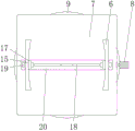
Fig. 1 is a schematic view of the structure of the present invention;
FIG. 2 is a schematic view of the front view of the internal structure of the fixing plate of the present invention;
fig. 3 is a schematic view of the top view of the fixing plate of the present invention;
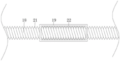
fig. 4 is a schematic view of the internal structure of the shaft sleeve of the present invention.
In the figure: 1. a first guide rail; 2. a second guide rail; 3. moving the plate; 4. a motor; 5. a sand roller; 6. a splint; 7. fixing the disc; 8. a handle is rotated; 9. an electric turntable; 10. a top plate; 11. a box base; 12. a box door; 13. a hinge; 14. a foot support; 15. a slider; 16. a groove; 17. a pulley; 18. a shaft lever; 19. a shaft sleeve; 20. a chute; 21. a first thread; 22. a second thread.
Detailed Description
The technical solutions in the embodiments of the present invention will be described clearly and completely with reference to the accompanying drawings in the embodiments of the present invention, and it is obvious that the described embodiments are only some embodiments of the present invention, not all embodiments. Based on the embodiments in the present invention, all other embodiments obtained by a person skilled in the art without creative work belong to the protection scope of the present invention.
Referring to fig. 1 to 4, the present invention provides a polishing device with a protection structure for cylinder head processing, which comprises: a polishing device with a protective structure for cylinder head processing comprises a top plate 10, a box seat 11 and a slide block 15, wherein a box door 12 is arranged on the front surface of the box seat 11, the box door 12 is rotatably arranged on the front surface of the box seat 11 through hinges 13, the box door 12 is arranged to enable the interior of the box seat 11 to be opened, so that workers can conveniently overhaul internal machines, foot supports 14 are arranged on the bottom surface of the box seat 11, the foot supports 14 are four, the four foot supports 14 are distributed in a rectangular shape, the polishing device can be stably placed and used, the top surface of the box seat 11 is fixedly provided with the top plate 10, one end of the top surface of the top plate 10 is fixedly provided with a first guide rail 1, the top surface of the first guide rail 1 is slidably provided with a second guide rail 2, the position height position and the transverse position of a motor 4 can be changed through the matching of the first guide rail 1 and the second guide rail 2, and the polishing position effect of a sand roller 5 is indirectly changed, the movable plate 3 is installed to the one end surface slidable of second guide rail 2, the fixed surface of movable plate 3 has motor 4, motor 4 adopts the Z6D-104 model, this model motor 4 rotational speed is fast, vibrations are low, it is novel to be applicable to this use, through setting up motor 4, make sand roller 5 can rotate, power take off's effect has been reached, motor 4's output is rotated and is installed sand roller 5, through setting up sand roller 5, make the hydro-cylinder internal surface of fixing on fixed disk 7 polish, the effect of dull polish polishing has been reached.
The other end of the top surface of the top plate 10 is fixed with an electric turntable 9, the fixed oil cylinder can rotate by arranging the electric turntable 9, the surface effect of rotating to change the interior of the oil cylinder to be polished is achieved, the surface of the electric turntable 9 is rotatably provided with a fixed disc 7, the interior of the fixed disc 7 is provided with a sliding groove 20, the interior of the sliding groove 20 is rotatably provided with a shaft lever 18, one end of the shaft lever 18 is fixed with a rotating handle 8, the installation of the rotating handle 8 enables a worker to conveniently apply rotating force to the shaft lever 18, a force application point is provided, shaft sleeves 19 are sleeved on the surfaces of the two ends of the shaft lever 18, second threads 22 and first threads 21 are respectively arranged on the inner surface of the shaft sleeve 19 and the outer surface of the shaft lever 18, the first threads 21 and the second threads 22 are meshed with each other, the position of the shaft sleeve 19 can be controlled by thread meshing when the shaft lever 18 rotates through the matching of the first threads 21 and the second threads 22, and the position effect of indirectly controlling the clamping plate 6 by thread meshing is achieved, the top of axle sleeve 19 is fixed with slider 15, slider 15's both sides are seted up flutedly 16, the pulley 17 is installed in the internal rotation of recess 16, and pulley 17 slides in the inside of spout 20, cooperation through pulley 17 and spout 20, make splint 6 can be stable move on fixed disk 7 surface, the effect of spacing removal has been reached, slider 15's top is fixed with splint 6, and splint 6 adopts arc structural design, through setting up splint 6, the laminating that splint 6 that adopts arc structural design can be better is at the hydro-cylinder surface of same circular arc structural design, reached and carried fixed effect.
The working principle is as follows: the utility model needs external power supply before using, then the worker vertically places the oil cylinder to be polished on the surface of the fixed disk 7, after placing, the worker holds the rotating handle 8 and applies rotating force, the shaft lever 18 rotates and can use the first thread 21 arranged on the surface to engage the second thread 22 arranged on the inner surface of the shaft sleeve 19, so the shaft sleeve 19 can move on the surface of the shaft lever 18, the clamp plate 6 arranged on the top surface of the shaft sleeve 19 can move, thereby the oil cylinder placed on the surface of the fixed disk 7 can be clamped and fixed, after clamping and fixing, the worker opens the switch and uses the computer to control the first guide rail 1 to move the second guide rail 2, thereby the height position of the sand roller 5 can be changed, after the sand roller 5 is lowered to the inside of the oil cylinder, the worker stops the movement of the first guide rail 1 and starts the movement of the second guide rail 2, and can move the transverse position of the sand roller 5 and paste the inner surface of the oil cylinder, therefore, the sand roller 5 polishes the inner surface of the oil cylinder, when the sand roller 5 is polished in a rotating mode, a worker starts the electric rotating disc 9 to rotate, the oil cylinder with the fixed disc 7 fixed on the surface can rotate, and the inner surface of the oil cylinder is uniformly polished by the sand roller 5.
Although embodiments of the present invention have been shown and described, it will be appreciated by those skilled in the art that changes, modifications, substitutions and alterations can be made in these embodiments without departing from the principles and spirit of the invention, the scope of which is defined in the appended claims and their equivalents.
Claims (6)
1. The utility model provides a burnishing device is used in cylinder head processing with protective structure, includes roof (10), case seat (11) and slider (15), its characterized in that: a top plate (10) is fixed on the top surface of the box base (11), a first guide rail (1) is fixed at one end of the top surface of the top plate (10), a second guide rail (2) is slidably mounted on the top end surface of the first guide rail (1), a movable plate (3) is slidably mounted on one end surface of the second guide rail (2), a motor (4) is fixed on the surface of the movable plate (3), a sand roller (5) is rotatably mounted at the output end of the motor (4), the top surface other end of roof (10) is fixed with electric turntable (9), and the surface rotation of electric turntable (9) installs fixed disk (7), and spout (20) have been seted up to the inside of fixed disk (7), and axostylus axostyle (18) are installed in the inside rotation of spout (20), and the one end of axostylus axostyle (18) is fixed with turning handle (8), and the both ends surface cover of axostylus axostyle (18) has axle sleeve (19), and the top of axle sleeve (19) is fixed with slider (15).
2. The polishing device with the protective structure for processing the cylinder head as claimed in claim 1, wherein: grooves (16) are formed in two sides of the sliding block (15), a pulley (17) is rotatably mounted in each groove (16), and the pulley (17) slides in the sliding groove (20).
3. The polishing device with the protective structure for processing the cylinder head as claimed in claim 1, wherein: the top of slider (15) is fixed with splint (6), and splint (6) adopt the design of arc structure.
4. The polishing device with the protective structure for processing the cylinder head as claimed in claim 1, wherein: the inner surface of the shaft sleeve (19) and the outer surface of the shaft rod (18) are respectively provided with a second thread (22) and a first thread (21), and the first thread (21) and the second thread (22) are mutually meshed.
5. The polishing device with the protective structure for processing the cylinder head as claimed in claim 1, wherein: the front surface of the box base (11) is provided with a box door (12), and the box door (12) is rotatably arranged on the front surface of the box base (11) through a hinge (13).
6. The polishing device with the protective structure for processing the cylinder head as claimed in claim 1, wherein: the bottom surface of the box seat (11) is provided with four foot supports (14), and the four foot supports (14) are distributed in a rectangular shape.
Priority Applications (1)
| Application Number | Priority Date | Filing Date | Title |
|---|---|---|---|
| CN202120291030.8U CN214771210U (en) | 2021-02-02 | 2021-02-02 | Burnishing device is used in cylinder head processing with protective structure |
Applications Claiming Priority (1)
| Application Number | Priority Date | Filing Date | Title |
|---|---|---|---|
| CN202120291030.8U CN214771210U (en) | 2021-02-02 | 2021-02-02 | Burnishing device is used in cylinder head processing with protective structure |
Publications (1)
| Publication Number | Publication Date |
|---|---|
| CN214771210U true CN214771210U (en) | 2021-11-19 |
Family
ID=78751635
Family Applications (1)
| Application Number | Title | Priority Date | Filing Date |
|---|---|---|---|
| CN202120291030.8U Active CN214771210U (en) | 2021-02-02 | 2021-02-02 | Burnishing device is used in cylinder head processing with protective structure |
Country Status (1)
| Country | Link |
|---|---|
| CN (1) | CN214771210U (en) |
Cited By (1)
| Publication number | Priority date | Publication date | Assignee | Title |
|---|---|---|---|---|
| CN114131507A (en) * | 2021-12-29 | 2022-03-04 | 重庆银晓科技发展有限公司 | Adjustable clamp for machining cylinder head |
-
2021
- 2021-02-02 CN CN202120291030.8U patent/CN214771210U/en active Active
Cited By (1)
| Publication number | Priority date | Publication date | Assignee | Title |
|---|---|---|---|---|
| CN114131507A (en) * | 2021-12-29 | 2022-03-04 | 重庆银晓科技发展有限公司 | Adjustable clamp for machining cylinder head |
Similar Documents
| Publication | Publication Date | Title |
|---|---|---|
| CN209954432U (en) | Burnishing device suitable for cylinder work piece | |
| CN214771210U (en) | Burnishing device is used in cylinder head processing with protective structure | |
| CN210024719U (en) | Rotating shaft polishing device for machining | |
| CN208163354U (en) | A kind of novel adjustable burnishing device | |
| CN203141256U (en) | High-precision bearing ring surface grinding machine | |
| CN209936575U (en) | Grinding device is used in bearing processing of convenient regulation | |
| CN219075291U (en) | Double-sided grinding polisher | |
| CN214080885U (en) | Part is polished and is used workstation with regulatory function | |
| CN105057790A (en) | Full-automatic diamond saw blade double-faced sharpening machine | |
| CN206326495U (en) | A kind of high-precision flat surface grinding | |
| CN211639349U (en) | Self-adjusting automatic polishing machine | |
| CN204893091U (en) | Full -automatic edging machine's of diamond saw blade rotatory and two -sided grinding mechanism of saw bit | |
| CN210938543U (en) | Arc-shaped grinding machine structure | |
| CN213592455U (en) | Grinding device is used in production of indoor lamp shade | |
| CN209007049U (en) | A kind of numerical controlled machinery processing turning polishing all-in-one machine | |
| CN113146375A (en) | Automatic machining equipment for precision mechanical parts | |
| CN103223631B (en) | A kind of high-accuracy bearing ring surface grinding machine | |
| CN217668339U (en) | Gantry grinding machine with double-sided transverse sliding rails | |
| CN216992093U (en) | A novel cutting tool for test bar processing | |
| CN204867644U (en) | Two -sided edging machine of full -automatic diamond saw blade | |
| CN214869602U (en) | Grinding machine device convenient for adjusting drilling position | |
| CN216939799U (en) | Cylindrical grinder with positioning function | |
| CN219901553U (en) | Grinding device is used in processing of machinery spare part | |
| CN217493760U (en) | Screw mould grinding and polishing processing device | |
| CN220408368U (en) | Numerical control guide rail grinding machine with grinding wheel dressing device |
Legal Events
| Date | Code | Title | Description |
|---|---|---|---|
| GR01 | Patent grant | ||
| GR01 | Patent grant |