CN214674203U - Plug-in structure of plug-in bus duct - Google Patents
Plug-in structure of plug-in bus duct Download PDFInfo
- Publication number
- CN214674203U CN214674203U CN202120776373.3U CN202120776373U CN214674203U CN 214674203 U CN214674203 U CN 214674203U CN 202120776373 U CN202120776373 U CN 202120776373U CN 214674203 U CN214674203 U CN 214674203U
- Authority
- CN
- China
- Prior art keywords
- bus duct
- mounting box
- duct body
- plug
- bus
- Prior art date
- Legal status (The legal status is an assumption and is not a legal conclusion. Google has not performed a legal analysis and makes no representation as to the accuracy of the status listed.)
- Active
Links
Images


Abstract
The utility model discloses a plug-in type bus duct plug-in structure, which relates to the technical field of bus ducts, and comprises a first bus duct body and a second bus duct body, wherein fixed blocks are respectively arranged inside the first bus duct body and the second bus duct body, and bus posts are arranged on the fixed blocks, a first mounting box is arranged at one end of the first bus duct body, a second mounting box is arranged at one end of the second bus duct body, insulating plates are respectively arranged inside the first mounting box and the second mounting box, and a jack is arranged at the middle part of each inserting tube, so that the plug-in speed of the two bus duct bodies is improved through the arranged first mounting box and the second mounting box, the mounting efficiency of the bus ducts is improved, the overall length of the two bus ducts is favorably lengthened through the mounting connecting plates arranged on the outer walls of the first mounting box and the second mounting box, the installation requirement of different length bus ducts is adapted.
Description
Technical Field
The utility model belongs to the technical field of the bus duct, concretely relates to plug-in type bus duct's grafting structure.
Background
The bus duct is a closed metal device formed by copper and aluminum bus posts, the traditional cable serving as a power transmission lead cannot meet the requirement in a large-current transmission system, the parallel connection of multiple cables brings inconvenience to on-site installation and construction connection, the plug-in bus duct serves as a novel power distribution lead, compared with the traditional cable, the plug-in bus duct fully shows the superiority during large-current transmission, but the existing plug-in bus duct still has defects during use, a plug between two bus ducts needs to be fixedly connected by a gasket insulation support and a bolt, the operation is complex, and the length of the plug-in structure cannot be adjusted.
SUMMERY OF THE UTILITY MODEL
An object of the utility model is to provide a plug-in structure of bayonet bus duct to the plug between two bus ducts that provide in solving above-mentioned background art needs earlier carry out fixed connection with gasket insulation support reuse bolt, and the operation is complicated, and the unable problem of adjusting length of plug-in structure.
In order to achieve the above object, the utility model provides a following technical scheme: the utility model provides a plug-in structure of bayonet bus duct, includes first bus duct body and second bus duct body, the fixed block is all installed to the inside of first bus duct body and second bus duct body, and installs the bus post on the fixed block, first mounting box is installed to the one end of first bus duct body, the second mounting box is installed to the one end of second bus duct body, the insulation board is all installed to the inside of first mounting box and second mounting box, and the internally mounted of insulation board has the intubate, the jack has been seted up at the middle part of intubate, the internally mounted of jack has the copper sheet.
Preferably, first mounting holes are symmetrically formed in two sides of the first mounting box, connecting plates are symmetrically mounted on two sides of the second mounting box, second fastening bolts are mounted between one end of each connecting plate and the second mounting box, and third fastening bolts are mounted between one side, close to the first mounting box, of each connecting plate and the first mounting box;
first mounting holes are formed in the connecting plate, second mounting holes are symmetrically formed in two sides of the first mounting box, and the first mounting holes are connected with the second mounting holes in a matched mode.
Preferably, a fourth fastening bolt is installed between the first bus duct body and the first mounting box, and a first fastening bolt is installed between the second bus duct body and the second mounting box.
Preferably, the first mounting box is of a hollow rectangular structure, and the first mounting box is made of plastic.
Preferably, the connecting plate is of a cuboid structure and is made of stainless steel or aluminum alloy.
Preferably, the cross section of the jack is rectangular, and the width of the bus bar post is in transition fit with the jack.
Compared with the prior art, the beneficial effects of the utility model are that:
(1) the utility model discloses a first mounting box and the second mounting box that set up, the first mounting box of the post disect insertion of the generating line of first bus duct body, the post disect insertion second mounting box of the generating line of second bus duct body need not install insulating gasket additional between the generating line post of first bus duct body and second bus duct body, has improved the grafting speed of two bus duct bodies, has improved the installation effectiveness of bus duct.
(2) The utility model discloses an at first mounting box and second mounting box outer wall erection joint board, seted up a plurality of first mounting holes on the connecting plate, the first mounting hole of difference cooperatees with the second mounting hole of first mounting box, can adjust the distance between first mounting box and the second mounting box to adjust the length of grafting structure, be favorable to lengthening the holistic length of two bus ducts, adapt to the installation demand of different length bus ducts.
Drawings
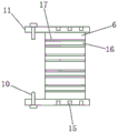
Fig. 1 is a schematic structural view of the present invention;
FIG. 2 is a side view of the first and second cases of the present invention;
FIG. 3 is a schematic structural view of the first box of the present invention;
fig. 4 is a front view of the first container of the present invention;
in the figure: 1-a first fastening bolt; 2-a second fastening bolt; 3-connecting the plates; 4-a third fastening bolt; 5-a first mounting hole; 6, insulating plates; 7-a busbar post; 8, fixing blocks; 9-a first bus duct body; 10-a fourth fastening bolt; 11-a first mounting box; 12-a copper sheet; 13-a second mounting box; 14-a second bus duct body; 15-a second mounting hole; 16-a jack; 17-cannula.
Detailed Description
The technical solutions in the embodiments of the present invention will be described clearly and completely with reference to the accompanying drawings in the embodiments of the present invention, and it is obvious that the described embodiments are only some embodiments of the present invention, not all embodiments. Based on the embodiments in the present invention, all other embodiments obtained by a person skilled in the art without creative work belong to the protection scope of the present invention.
Referring to fig. 1-4, the present invention provides the following technical solutions: a plug-in type bus duct plug-in structure comprises a first bus duct body 9 and a second bus duct body 14, wherein fixed blocks 8 are arranged inside the first bus duct body 9 and the second bus duct body 14 respectively, a bus post 7 is arranged on each fixed block 8, a first mounting box 11 is arranged at one end of the first bus duct body 9, a second mounting box 13 is arranged at one end of the second bus duct body 14, insulating plates 6 are arranged inside the first mounting box 11 and the second mounting box 13 respectively, an insertion pipe 17 is arranged inside each insulating plate 6, a jack 16 is arranged in the middle of each insertion pipe 17, a copper sheet 12 is arranged inside each jack 16, the cross section of the second bus duct body 14 is rectangular, the second bus duct body 14 is in transition fit with the first mounting box 11, the second bus duct body 14 is directly inserted into the first mounting box 11, the bus post 7 is inserted into the jack 16, the bus post 7 is in contact with the insertion pipe 17, meanwhile, the copper sheet 12 is in contact with the insertion tube 17, the other end of the copper sheet 12 is in contact with the insertion tube 17 in the second mounting box 13, and the bus post 7 in the first bus duct body 9 is communicated with the bus post 7 in the second bus duct body 14, so that electric conduction is realized.
Furthermore, first mounting holes 5 are symmetrically formed in two sides of the first mounting box 11, connecting plates 3 are symmetrically mounted on two sides of the second mounting box 13, second fastening bolts 2 are mounted between one end of each connecting plate 3 and the second mounting box 13, and third fastening bolts 4 are mounted between one side, close to the first mounting box 11, of each connecting plate 3 and the first mounting box 11;
Further, a fourth fastening bolt 10 is installed between the first bus duct body 9 and the first mounting box 11, a first fastening bolt 1 is installed between the second bus duct body 14 and the second mounting box 13, the fourth fastening bolt 10 is used for fixing the first mounting box 11 on the outer wall of the first bus duct body 9, and the first fastening bolt 1 is used for fixing the second mounting box 13 on the outer wall of the second bus duct body 14.
Further, the first mounting box 11 is a hollow rectangular structure, and the first mounting box 11 is made of plastic.
Further, the connecting plate 3 is of a cuboid structure, and the connecting plate 3 is made of stainless steel or aluminum alloy.
Furthermore, the cross section of the jack 16 is rectangular, and the width of the bus bar post 7 is in transition fit with the jack 16.
Although embodiments of the present invention have been shown and described, it will be appreciated by those skilled in the art that changes, modifications, substitutions and alterations can be made in these embodiments without departing from the principles and spirit of the invention, the scope of which is defined in the appended claims and their equivalents.
Claims (6)
1. The utility model provides a plug-in structure of bayonet bus duct which characterized in that: including first bus duct body (9) and second bus duct body (14), fixed block (8) are all installed to the inside of first bus duct body (9) and second bus duct body (14), and install bus post (7) on fixed block (8), first mounting box (11) are installed to the one end of first bus duct body (9), second mounting box (13) are installed to the one end of second bus duct body (14), insulation board (6) are all installed to the inside of first mounting box (11) and second mounting box (13), and the internally mounted of insulation board (6) has intubate (17), jack (16) have been seted up at the middle part of intubate (17), the internally mounted of jack (16) has copper sheet (12).
2. The plugging structure of the plug-in bus duct according to claim 1, characterized in that: first mounting holes (5) are symmetrically formed in two sides of the first mounting box (11), connecting plates (3) are symmetrically mounted on two sides of the second mounting box (13), second fastening bolts (2) are mounted between one end of each connecting plate (3) and the second mounting box (13), and third fastening bolts (4) are mounted between one side, close to the first mounting box (11), of each connecting plate (3) and the first mounting box (11);
first mounting hole (5) have been seted up to the inside of connecting plate (3), second mounting hole (15) have been seted up to the bilateral symmetry of first mounting box (11), first mounting hole (5) are connected with second mounting hole (15) cooperation.
3. The plugging structure of the plug-in bus duct according to claim 1, characterized in that: a fourth fastening bolt (10) is installed between the first bus duct body (9) and the first installation box (11), and a first fastening bolt (1) is installed between the second bus duct body (14) and the second installation box (13).
4. The plugging structure of the plug-in bus duct according to claim 1, characterized in that: the first mounting box (11) is of a hollow rectangular structure, and the first mounting box (11) is made of plastic.
5. The plugging structure of the plug-in bus duct according to claim 2, characterized in that: the connecting plate (3) is of a cuboid structure, and the connecting plate (3) is made of stainless steel or aluminum alloy.
6. The plugging structure of the plug-in bus duct according to claim 1, characterized in that: the section of the jack (16) is rectangular, and the width of the bus bar (7) is in transition fit with the jack (16).
Priority Applications (1)
| Application Number | Priority Date | Filing Date | Title |
|---|---|---|---|
| CN202120776373.3U CN214674203U (en) | 2021-04-16 | 2021-04-16 | Plug-in structure of plug-in bus duct |
Applications Claiming Priority (1)
| Application Number | Priority Date | Filing Date | Title |
|---|---|---|---|
| CN202120776373.3U CN214674203U (en) | 2021-04-16 | 2021-04-16 | Plug-in structure of plug-in bus duct |
Publications (1)
| Publication Number | Publication Date |
|---|---|
| CN214674203U true CN214674203U (en) | 2021-11-09 |
Family
ID=78462735
Family Applications (1)
| Application Number | Title | Priority Date | Filing Date |
|---|---|---|---|
| CN202120776373.3U Active CN214674203U (en) | 2021-04-16 | 2021-04-16 | Plug-in structure of plug-in bus duct |
Country Status (1)
| Country | Link |
|---|---|
| CN (1) | CN214674203U (en) |
-
2021
- 2021-04-16 CN CN202120776373.3U patent/CN214674203U/en active Active
Similar Documents
| Publication | Publication Date | Title |
|---|---|---|
| CN201829890U (en) | Clamping connection type bus duct shell | |
| CN212011682U (en) | High-voltage board convenient to dismantle installation | |
| CN214674203U (en) | Plug-in structure of plug-in bus duct | |
| CN205159966U (en) | Cable pipe | |
| CN210074361U (en) | Flexible power connector of bus duct | |
| CN219690724U (en) | Modular building box structure with equipotential connection | |
| CN220209918U (en) | Sealing structure and bus duct thereof | |
| CN219436605U (en) | Bus connection device for horizontal three-way bus duct | |
| CN217087249U (en) | Frame type power distribution plug box | |
| CN213027343U (en) | Bus duct convenient to installation has grafting conversion function | |
| CN216624987U (en) | Photovoltaic box-type substation convenient to equipment | |
| CN216215725U (en) | Novel air bus duct cover plate | |
| CN110556769A (en) | High-strength bus duct | |
| CN219268431U (en) | Direct current bus duct structure | |
| CN213278620U (en) | U-shaped bus connector | |
| CN217956639U (en) | Air type bus duct electricity control equipment | |
| CN101895074A (en) | Device for connecting buses at right angle in plane | |
| CN213905615U (en) | Special-shaped ion grounding module | |
| CN203377796U (en) | Laminated busbar connection structure of oppositely-plugged type | |
| CN219420719U (en) | Combiner box and photovoltaic power station | |
| CN114883996B (en) | Plug-in bus duct with telescopic plug-in port and connection method thereof | |
| CN220896295U (en) | Bus duct with T-shaped heat dissipation structure | |
| CN219611299U (en) | Four-way connecting piece | |
| CN216252082U (en) | Environment-friendly bus duct for Internet of things | |
| CN216981469U (en) | Anticreep insulation protection device for bus duct |
Legal Events
| Date | Code | Title | Description |
|---|---|---|---|
| GR01 | Patent grant | ||
| GR01 | Patent grant |