CN214619687U - Multifunctional heat-insulating pressure-bearing hot water stove - Google Patents
Multifunctional heat-insulating pressure-bearing hot water stove Download PDFInfo
- Publication number
- CN214619687U CN214619687U CN202121001500.9U CN202121001500U CN214619687U CN 214619687 U CN214619687 U CN 214619687U CN 202121001500 U CN202121001500 U CN 202121001500U CN 214619687 U CN214619687 U CN 214619687U
- Authority
- CN
- China
- Prior art keywords
- heat
- heat exchanger
- hearth
- stove
- hot water
- Prior art date
- Legal status (The legal status is an assumption and is not a legal conclusion. Google has not performed a legal analysis and makes no representation as to the accuracy of the status listed.)
- Active
Links
Images


Abstract
The utility model provides a multi-functional heat preservation pressure-bearing hot water kitchen belongs to cooking utensil technical field. The multifunctional heat-preservation pressure-bearing hot water stove comprises a stove body, a stove chamber, a heat preservation water tank, a stove chamber heat exchanger, an intelligent controller, a water inlet, a water outlet, a drain outlet and a hot water tap, wherein the heat preservation water tank and the stove chamber heat exchanger are arranged on the outer wall of the stove chamber, the intelligent controller, the water inlet, the water outlet, the drain outlet and the hot water tap are arranged outside the stove body, the heat preservation water tank is connected with the stove chamber heat exchanger, and the stove chamber heat exchanger is connected with the intelligent controller. The utility model makes the hearth and the outer side of the hearth of the firewood and coal double stove into a jacket type or a tubular heat exchanger, which can fully absorb the heat dissipated by the hearth; the special-shaped heat-insulating water tank integrated in the stove body is adopted, so that the space of the stove body can be fully utilized, and the heat-insulating water tank has excellent water storage performance and heat-insulating function; the hearth adopts an integrated jacket type or tubular heat exchanger, so that most hearth walls serve as heat exchange surfaces, and the heat exchange surfaces and the heat production speed are guaranteed.
Description
Technical Field
The utility model belongs to the technical field of the cooking utensil, concretely relates to multi-functional heat preservation pressure-bearing hot water kitchen.
Background
The mode of taking heat most in rural life in China is to cook food and produce hot water by using heat obtained by burning firewood, crop straws, coal and the like through a pot stove. The structure and combustion characteristics of the conventional cooking stove enable the heat utilization rate of the cooking stove to be extremely low, and most heat is dissipated through the stove body and smoke. People install a special iron pan (or other metal containers) beside the range of the traditional earthen range to absorb the residual heat of the range chamber to produce a small amount of hot water. Aiming at a pot stove produced in a factory in a standardized manner, a water tank is arranged in a stove body, and the heat of the stove is absorbed by the metal inner wall of the stove chamber through fire clay to produce hot water. And an auxiliary water tank is also arranged at the position of the chimney and absorbs the waste heat of the flue gas to produce hot water. Although the hot water stove for utilizing the waste heat of the stove and producing hot water has certain practicability, the hot water stove still has a plurality of defects, and the main defects are as follows:
1. the mode of installing the iron pan (or other metal containers) in the earth stove is that the heat exchange surface is small, the heat utilization of the stove hearth is less, the provided water temperature is not high, the yield of hot water is low, and meanwhile, after the stove hearth does not generate fire, the hot water heat of the iron pan (or other metal containers) can be conducted to the stove hearth and the air, so that the heat loss is fast and the heat is not preserved. 2. The metal inner wall of the hearth and the shell space of the hearth are used as a water tank of a part of hot water stove, the hearth inner wall is used for absorbing hearth heat conducted by fire clay to produce hot water, and water is used as heat insulation of the stove body, so that the radiating surface of the water tank is extremely large, and the water temperature is rapidly reduced and does not keep warm after no fire is generated in the hearth. 3. Although some improved hot water stoves have heat insulating measures set between the outer wall of the water tank and the outer casing of the stove body, the inner wall of the stove chamber is still used directly to absorb the heat of the stove chamber conducted by the fire clay to produce hot water, the fire clay has poor heat insulating performance, and after a fire is not produced, the fire clay with large area in the stove chamber is directly changed into a radiator with large area, so that the heat insulating performance of the water tank is extremely poor. 4. Other hot water stoves adopting a chimney-type water tank or hot water stoves burning coal cakes also have the problems of large heat radiating surface, non-heat preservation of the water tank or poor heat preservation performance because one surface structure of the water tank is directly adopted as a heat exchanger. 5. The conventional water heating stove adopts a structure of one side of a water tank as a heat exchanger, and after the temperature of water close to a heat source part is increased, the heat exchange is slowed down, and finally the available heat and the temperature of available hot water are influenced. 6. The conventional water tank closed type hot water stove belongs to a small normal pressure hot water boiler, must obtain a manufacturing license of the small normal pressure hot water boiler, has no monitoring and control equipment and no data communication function, and cannot perform intelligent control and protection and data acquisition and management in the era of intellectualization, Internet of things and big data.
SUMMERY OF THE UTILITY MODEL
The utility model provides a multifunctional heat-preservation pressure-bearing hot water stove to solve the technical problem that the hot water heat preservation performance in the existing hot water stove is not enough.
In order to achieve the above object, the technical solution of the present invention is:
the utility model provides a multi-functional heat preservation pressure-bearing hot water kitchen, includes the kitchen body, kitchen thorax, holding water box, kitchen thorax heat exchanger, intelligent control ware, water inlet, delivery port, drain, hot water tap, holding water box and kitchen thorax heat exchanger set up in kitchen thorax outer wall, intelligent control ware, water inlet, delivery port, drain, hot water tap set up in the outside of the kitchen body, and holding water box and kitchen thorax heat exchanger are connected, and kitchen thorax heat exchanger is connected with the intelligent control ware.
Preferably, the hot-water oven still includes furnace and furnace heat exchanger, and furnace installs in the kitchen body, and the outer wall of furnace is located to the furnace heat exchanger, and the furnace heat exchanger is connected with intelligent control ware.
Preferably, the hot water stove further comprises a chimney and a chimney heat exchanger, wherein the chimney heat exchanger is arranged in the chimney and is connected with the intelligent controller; the chimney is fixed at a hole position connected with the smoke discharge flue at the back of the stove body through the adapter piece and the mounting bolt, or the chimney is vertically arranged on the table top of the stove body and connected with the smoke discharge flue; the hearth heat exchanger, the chimney heat exchanger and the hearth heat exchanger jointly form a heat exchange system.
Preferably, the hearth is made of refractory mortar, a smoke discharge channel connected with the chimney is arranged at the position, close to the chimney, of the hearth, a first fire grate and a first air vent are arranged at the bottom of the hearth, a first heat insulation layer is arranged on the periphery of the hearth, a hearth opening is arranged on the front side of the hearth, a hearth door capable of being closed or opened is installed on the hearth opening, the first air vent is connected with an extractable ash bucket, and a shutter is arranged on the ash bucket; the periphery of the hearth is provided with a second heat insulation layer, the bottom of the hearth is provided with a second grate and a second vent, and a cover cap capable of adjusting air inflow is arranged at the position where the second vent is connected to the outer shell of the stove body.
Preferably, holding water box is the dysmorphism structure, is equipped with the portion of dodging on the holding water box, and the portion of dodging makes things convenient for putting of first blow vent.
Preferably, the heat preservation water tank is provided with a corrosion-resistant metal inner container, a shell and a heat preservation layer, and is provided with a safety valve mounting opening, an electric heating rod, a hot water outlet, a hot water temperature measuring hole, an anti-corrosion magnesium rod, a heat exchange circulation water inlet, a water tank bottom temperature measuring hole, a heat exchange circulation water outlet, a water inlet and a sewage outlet.
Preferably, the fire clay of the hearth is coated on the metal inner wall of the hearth, and the hearth heat exchanger is integrally designed in the fire clay layer of the hearth; the hearth heat exchanger is formed by welding a jacket plate on a hearth metal wall to form a semi-annular jacket heat exchanger, and a first circulating working medium inflow port and a first circulating working medium outflow port are arranged at two ends of the hearth heat exchanger in the direction of a first heat insulation layer; the hearth heat exchanger is arranged on the metal wall of the hearth through a plurality of metal clamping strips and a plurality of fixing screws.
Preferably, the chimney heat exchanger is an annular jacketed heat exchanger formed by welding heat exchange plates in a chimney, and the upper end and the lower end of the two sides of the chimney heat exchanger are respectively provided with a second circulating working medium inflow port and a second circulating working medium outflow port; an anti-scald net is arranged at the periphery of the chimney; and a second circulating working medium inflow port and a second circulating working medium outflow port of the chimney heat exchanger are connected into the stove body through pipelines.
Preferably, the hearth heat exchanger is an annular jacketed heat exchanger formed by welding the outer wall of the heat exchanger and the inner wall of the heat exchanger, and a third circulating working medium outlet and a third circulating working medium inlet are formed in the upper end and the lower end of the two sides of the hearth heat exchanger in the direction towards the second heat insulation layer.
Preferably, the controller is powered by mains supply, is internally provided with an alarm and is connected with the first temperature probe, the second temperature probe, the third temperature probe, the circulating pump, the electric heating rod and the electromagnetic valve through lines; the first temperature probe is arranged at a circulating working medium flow outlet of the heat exchanger system (namely, the joint of the circulating pipeline 18-2 and the heat exchanger system 18), and can detect the temperature T1 of the circulating working medium of the heat exchanger system; the second temperature probe is arranged in a temperature measuring hole at the bottom of the heat-preservation water tank and can detect the water temperature at the bottom of the heat-preservation water tank; the third temperature probe is arranged in a hot water temperature measuring hole of the heat preservation water tank and can detect the hot water temperature T3 of the heat preservation water tank.
The utility model has the advantages that:
1. in the application, a hearth in the firewood and coal double stove and the outer side of the hearth are manufactured into jacketed or tubular heat exchangers, so that the heat dissipated by the hearth can be fully absorbed; the special-shaped heat-insulating water tank integrated in the stove body is adopted, so that the space of the stove body can be fully utilized, and the heat-insulating water tank has excellent water storage performance and heat-insulating function; the hearth adopts an integrated jacket type or tubular heat exchanger, so that most hearth walls serve as heat exchange surfaces, and the heat exchange surfaces and the heat production speed are guaranteed; the chimney adopts the built-in tubular heat exchanger, can form secondary heat exchange system with the heat exchanger in the hearth, can preferentially utilize the flue gas waste heat, reduce the heat absorption of the heat exchanger to the hearth, and is energy-saving and effectual.
2. The heat-preservation water tank and the heat exchanger are connected by adopting a circulating pipeline with a small sectional area, so that the heat-dissipation section of the heat-preservation water tank in a non-working state is only the size of the section of the circulating pipeline, and the heat preservation of the water tank is facilitated; meanwhile, a direct heat exchange mode and a temperature difference circulation scheme are adopted, water in the heat preservation water tank is used as a heat exchange working medium, the structure is simple, the heat exchange times are reduced, and the heat exchange efficiency is improved.
3. Adopt intelligent control ware, according to the temperature of hearth and furnace side to and the difference of temperature in the holding water box, but opening of intelligent control circulating water pump stops, saves circulating water pump power consumption, and can prevent that hot water from passing through the reverse heat dissipation of heat exchanger in the holding water box.
4. The heat preservation water tank, the heat exchanger and the heat exchange circulating pipeline are made of metal materials, water in the heat preservation water tank is used as a heat exchange working medium, when faults or equipment such as a circulating pump, a controller and a temperature sensor are powered off, after hot water in the heat exchanger is heated continuously to form steam, the steam pressure can drive the water in the heat exchange circulating pipeline to perform forced self-circulation, and the heat preservation water tank, the heat exchanger and the heat exchange circulating pipeline are safe and reliable; the heat preservation water tank is provided with supplementary electric heating function, accessible intelligent control ware automatic control.
5. The water tank overpressure safety valve automatic pressure relief and hot water over-temperature self-drainage dual-protection function controlled by the intelligent controller are adopted, so that the phenomenon that a water body is overheated and vaporized due to electric heating faults or excessive waste heat absorption of the heat preservation water tank is avoided, and the danger of accidental scalding or explosion can be avoided; the circulating heat exchange pipeline is divided into two sub heat exchange loops by adopting the water mixing valve and the tee joint, and the corresponding sub heat exchanger systems are matched, so that the waste heat utilization of any fired hearth or two fired hearts (or the hearth and the hearth) can be realized, the utilization amount of the waste heat is increased, and the temperature and the yield of hot water are increased.
6. The system adopts a temperature difference circulation controller with data communication capacity, realizes the internet of things, can realize the remote monitoring, intelligent management, fault alarm, remote maintenance and other work of the system by combining with corresponding APP, adopts an integrated terminal design, and can be used by simply installing a chimney, a water inlet pipe and a water outlet pipe.
Drawings
FIG. 1 is a first schematic view of a multifunctional heat-preservation hot water stove (dual-purpose firewood and coal stove) of the invention;
FIG. 2 is a schematic view of a multifunctional heat-preservation water heating stove (dual-purpose firewood and coal stove) of the invention;
FIG. 3 is a schematic view of a multifunctional heat-preservation water heating stove (single-stove firewood and coal dual-purpose) of the invention;
FIG. 4 is a schematic view of a multifunctional heat-preservation water heating stove (single stove for single briquette) according to the present invention;
FIG. 5 is a schematic view of an integrated holding water tank arrangement of the present invention;
FIG. 6 is a schematic view of the arrangement of the integrated holding water tank of the present invention;
FIG. 7 is a schematic perspective view of an integrated holding tank of the present invention;
FIG. 8 is a first schematic view of the appearance of the integrated holding water tank of the present invention;
FIG. 9 is a schematic diagram of the appearance of the integrated holding water tank of the present invention;
FIG. 10 is a first schematic view of a hearth heat exchanger arrangement of the present invention;
FIG. 11 is a sectional view of a chamber heat exchanger A-A of the present invention;
FIG. 12 is a second schematic view of a hearth heat exchanger arrangement of the present invention;
FIG. 13 is a schematic view of a chamber heat exchanger M of the present invention in elevation;
FIG. 14 is a sectional view of a hearth heat exchanger B-B of the present invention;
FIG. 15 is a schematic cross-sectional view of a 304 stainless steel bellows of the present invention;
FIG. 16 is a schematic view of a 304 stainless steel bellows in a bent section according to the present invention;
FIG. 17 is a schematic top view in horizontal cross section of a chimney heat exchanger according to the present invention;
FIG. 18 is a schematic cross-sectional view of a chimney heat exchanger C-C according to the present invention;
FIG. 19 is a second schematic diagram of a horizontal cross-section top view of a chimney heat exchanger according to the present invention;
FIG. 20 is a schematic cross-sectional view of a chimney heat exchanger D-D of the present invention;
FIG. 21 is a first schematic view of a furnace heat exchanger arrangement of the present invention;
FIG. 22 is a cross-sectional view of the furnace heat exchanger E-E of the present invention;
FIG. 23 is a second schematic view of a furnace heat exchanger arrangement of the present invention;
FIG. 24 is a sectional view of a hearth heat exchanger F-F of the present invention;
FIG. 25 is a schematic view of the chimney installation of the present invention;
FIG. 26 is a schematic view of the chimney of the present invention in the N direction;
FIG. 27 is a first schematic view of a 304 stainless steel bellows connection according to the present invention;
FIG. 28 is a second schematic view of a 304 stainless steel bellows connection according to the present invention;
FIG. 29 is a first schematic view of a heat exchanger system of the present invention;
FIG. 30 is a second schematic view of the heat exchanger system of the present invention;
FIG. 31 is a third schematic view of a heat exchanger system of the present invention;
FIG. 32 is a fourth schematic view of the heat exchanger system of the present invention;
FIG. 33 is a schematic view of the hot water system of the present invention;
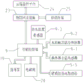
FIG. 34 is a first block diagram of the system operation of the present invention;
FIG. 35 is a second block diagram of the system operation of the present invention.
Detailed Description
The technical solutions in the embodiments of the present invention will be described clearly and completely with reference to the accompanying drawings in the embodiments of the present invention, and it is obvious that the described embodiments are only some embodiments of the present invention, not all embodiments. Based on the embodiments in the present invention, all other embodiments obtained by a person skilled in the art without creative efforts belong to the protection scope of the present invention.
It should be noted that all the directional indicators (such as upper, lower, left, right, front and rear … …) in the embodiment of the present invention are only used to explain the relative position relationship between the components, the motion situation, etc. in a specific posture (as shown in the drawings), and if the specific posture is changed, the directional indicator is changed accordingly.
In addition, descriptions in the present application as to "first", "second", and the like are for descriptive purposes only and are not to be construed as indicating or implying relative importance or implicit to the number of technical features indicated. Thus, a feature defined as "first" or "second" may explicitly or implicitly include at least one such feature. In the description of the present invention, "a plurality" means at least two, e.g., two, three, etc., unless specifically limited otherwise.
In the present application, unless expressly stated or limited otherwise, the terms "connected" and "fixed" are to be construed broadly, e.g., "fixed" may be fixedly connected or detachably connected, or integrally formed; they may be directly connected or indirectly connected through intervening media, or they may be connected internally or in any other suitable relationship, unless expressly stated otherwise. The specific meaning of the above terms in the present invention can be understood according to specific situations by those skilled in the art.
In addition, the technical solutions between the embodiments of the present invention can be combined with each other, but it is necessary to be able to be realized by a person having ordinary skill in the art as a basis, and when the technical solutions are contradictory or cannot be realized, the combination of such technical solutions should be considered to be absent, and is not within the protection scope of the present invention.
As shown in fig. 1, fig. 2, fig. 3 and fig. 4, a multifunctional heat-preservation pressure-bearing hot water stove comprises a stove body 1, a stove chamber 2, a heat preservation water tank 5, a stove chamber heat exchanger 6, an intelligent controller 7, a water inlet 10, a water outlet 11, a water mixing valve 12, a sewage draining outlet 13 and a hot water tap 14, wherein the heat preservation water tank 5 and the stove chamber heat exchanger 6 are arranged on the outer wall of the stove chamber, the intelligent controller 7, the water inlet 10, the water outlet 11, the water mixing valve 12, the sewage draining outlet 13 and the hot water tap 14 are arranged outside the stove body, the heat preservation water tank is connected with the stove chamber heat exchanger, and the stove chamber heat exchanger is connected with the intelligent controller. The bottom of the stove body 1 is provided with universal wheels 1-2 with brakes, and the side surface of the cooking bench of the stove body 1 is provided with a detachable or foldable table top 1-3, so that the space of the cooking bench can be temporarily increased.
In another preferred embodiment, the hot water stove further comprises a hearth 4 and a hearth heat exchanger 8, the hearth 4 is installed in the stove body, the hearth heat exchanger 8 is arranged on the outer wall of the hearth, and the hearth heat exchanger is connected with the intelligent controller.
In another more preferred embodiment, the hot water stove further comprises a chimney 3 and a chimney heat exchanger 7, wherein the chimney heat exchanger 7 is arranged in the chimney 3 and is connected with the intelligent controller 7; the chimney is fixed on a hole position on the back of the stove body connected with the smoke discharge flue through the adapter piece and the mounting bolt, or the chimney is vertically arranged on the table top of the stove body and connected with the smoke discharge flue. The water inlet 10, the hot water outlet 11 and the sewage outlet 13 are uniformly arranged at one side of the stove body 1, so that the pipeline arrangement at the user side is convenient, and meanwhile, the working power cord of the multifunctional heat-preservation pressure-bearing hot water stove is also led in from the side. A hot water tap 14 at the front part of the stove body 1 is connected with a hot water outlet pipeline of the self-insulation water tank 5.
Furthermore, the hearth 2 is made of refractory mortar, a hearth heat exchanger 6 is arranged inside the hearth 2 (in the direction of a non-hearth space), a smoke discharge flue 2-1 connected with the chimney 3 is arranged at the position, close to the chimney, of the hearth, a first fire grate 2-2 and a first air vent 2-6 are arranged at the bottom of the hearth, a first heat insulation layer 2-3 is arranged on the periphery of the hearth, a hearth opening 2-4 is arranged on the front side of the hearth, and a hearth door 2-5 capable of being closed or opened is arranged on the hearth opening 2-4; the air vent 2-6 is connected with an ash bucket 2-7 which can be drawn out, and a shutter is arranged on the ash bucket 2-7; a hearth heat exchanger 8 is arranged around the outer wall of the hearth 4, a second heat insulation layer 4-1 is arranged on the periphery of the hearth, a second grate 4-2 and a second air vent 4-3 are arranged at the bottom of the hearth, and a cover 4-4 capable of adjusting air inflow is arranged at the position where the second air vent 4-3 is connected to the outer shell of the stove body.
As shown in fig. 5 and 6, the heat preservation water tank 5 is of a special-shaped structure, and an avoiding portion is arranged on the heat preservation water tank and facilitates placement of the first vent. The heat-insulating water tank 5 is arranged in the stove body 1 according to the scheme shown in the figure, the avoidance part can avoid the first air vents 2-6 connected with the stove body 2, the residual space of the stove body is fully utilized, and the capacity requirement and the water storage performance of the heat-insulating water tank 5 under the condition of limiting the height are guaranteed.
As shown in the figures 7, 8 and 9, the heat preservation water tank 5 is provided with a corrosion-resistant metal inner container 5-1, a shell 5-2, a heat preservation layer 5-3, a safety valve mounting port 5-4, an electric heating rod 5-5, a hot water outlet 5-6, a hot water temperature measuring hole 5-7, an anti-corrosion magnesium rod 5-8, a heat exchange circulation water inlet 5-9, a water tank bottom temperature measuring hole 5-10, a heat exchange circulation water outlet 5-11, a water inlet 5-12 and a sewage outlet 5-13.
The inner container 5-1 can be made of corrosion-resistant 304 stainless steel or carbon steel and is subjected to inner enamel treatment to avoid corrosion; the shell 5-2 can be made of color steel plates or stainless steel sheets, and also can be directly made of a part of the shell of the stove body 1; the heat-insulating layer 5-3 is formed by integrally foaming polyurethane in the space between the inner container 5-1 and the outer shell 5-2, and has good heat-insulating effect; the safety valve mounting port 5-4 can be provided with a safety relief valve; the hot water temperature measuring holes 5-7 and the water tank bottom temperature measuring holes 5-10 adopt a blind pipe buried pipe design, so that an external temperature sensor can penetrate deeply and measure the water temperature at the corresponding position; the magnesium rods 5-8 play a role in preventing the corrosion of the water tank and purifying the water quality. Similarly, the water outlets 5-12 and the hot water outlets 5-6 are arranged diagonally and vertically, so that the entering cold water flow can be prevented from being mixed into the hot water layer, and the stability of the hot water in use can be guaranteed. Similar to the figure, the heat exchange circulating water outlets 5-11 and the heat exchange circulating water inlets 5-9 are arranged diagonally and vertically, so that high-temperature hot water entering through heat exchange can be prevented from being sucked into the circulating water outlets immediately for heat exchange again (the heat exchange is fast and efficient when the temperature is high and low), the uniformity of heat exchange is guaranteed, and the heat exchange efficiency is improved. Similar to the figure, the arrangement of the hot water temperature detection blind holes 5-7 and the electric heating rods 5-5 close to the hot water outlet 5-6 is adopted, so that the accuracy of hot water temperature detection, the hot water production speed during electric auxiliary heating and energy-saving control can be effectively guaranteed. The arrangement of the water inlet 5-12 and the sewage discharge outlet 5-13 opposite to each other is adopted similarly to the illustration, which is beneficial to improving the sewage cleaning efficiency. In short, under the principle of ensuring the best use performance of the heat preservation water tank, the arrangement of each port in the figure can be adjusted according to the actual situation, and is not limited to the figure.
As shown in fig. 10 and 11, the fire clay of the hearth 2 is coated on the metal inner wall 6-1 of the hearth, and the hearth heat exchanger 6 of the present application is integrally designed in the fire clay layer of the hearth 2. The hearth heat exchanger 6 can be formed by a semi-annular jacketed heat exchanger formed by welding a jacketed plate 6-2 on a hearth metal wall 6-1, and a first circulating working medium inflow port 6-3 and a first circulating working medium outflow port 6-4 are arranged at two ends of the hearth heat exchanger 6 in the direction of the heat insulation layer 2-3; the corresponding material of the hearth heat exchanger 6 can be made of high-temperature-resistant and corrosion-resistant sheet stainless steel, and reinforcing measures can be taken for the sheet when pressure bearing requirements exist.
As shown in fig. 12, 13, 14, 15, 16, the chamber heat exchanger 6 is covered on the metal wall 6-1 of the chamber by the chamotte of the chamber 2, and the chamber heat exchanger 6 is designed integrally in the chamotte layer of the chamber 2. The hearth heat exchanger 6 can be formed by bending a 304 stainless steel corrugated pipe into a multi-layer semi-annular tubular heat exchanger shown in the figure, and a first circulating working medium inlet 6-3 and a first circulating working medium outlet 6-4 are formed at two ends of the hearth heat exchanger 6 towards the direction of the first heat insulation layer 2-3. The hearth heat exchanger 6 can be arranged on a hearth metal wall 6-1 through a plurality of metal clamping strips 6-5 and a plurality of fixing screw rods 6-6.
As shown in fig. 17 and 18, the chimney heat exchanger 7 is an annular jacketed heat exchanger formed by welding a heat exchange plate 7-1 in the chimney 3, and a second circulating working medium inlet 7-3 and a second circulating working medium outlet 7-2 are respectively arranged at the upper end and the lower end of both sides of the chimney heat exchanger; an anti-scald net 3-1 is arranged at the periphery of the chimney; and a second circulating working medium inflow port and a second circulating working medium outflow port of the chimney heat exchanger are connected into the stove body through pipelines. The corresponding material of the hearth heat exchanger 7 can be thin stainless steel or aluminum plate, and when pressure-bearing requirements are met, reinforcing measures can be taken for the plate.
As shown in fig. 19 and 20, the chimney heat exchanger 7 may be formed by winding a 304 stainless steel corrugated pipe in the chimney 3 to form a multilayer pipe heat exchanger as shown in the figure, and a second circulating fluid inlet 7-3 and a second circulating fluid outlet 7-2 are respectively arranged at the upper and lower ends of both sides of the chimney heat exchanger 7. Meanwhile, the periphery of the chimney 3 is provided with an anti-scald net 3-1, and the inner wall of the chimney 3 is provided with a bracket 3-2 for supporting a heat exchanger 7. The upper end of the chimney is gradually far away from a heat source of the hearth, the temperature is gradually reduced, and the heat conduction is faster as the temperature difference is larger, so that the second circulating working medium inflow port 7-3 of the chimney heat exchanger is arranged at the upper end, and the heat exchange working medium can fully absorb the waste heat of the chimney.
As shown in fig. 21 and 22, the hearth heat exchanger 8 is an annular jacketed heat exchanger formed by welding an outer wall 8-1 of the heat exchanger and an inner wall 8-2 of the heat exchanger, and a third circulating working medium outlet 8-4 and a third circulating working medium inlet 8-3 are arranged at the upper and lower ends of the two sides of the hearth heat exchanger 8 in the direction of the second heat insulating layer 4-1. The corresponding material of the hearth heat exchanger 8 is made of high-temperature-resistant and corrosion-resistant sheet stainless steel, and when pressure-bearing requirements exist, reinforcing measures can be taken for the sheet.
As shown in fig. 23 and 24, the furnace heat exchanger 8 can be formed by winding 304 stainless steel corrugated pipes to form a multi-layer pipe heat exchanger as shown in the figure, and the upper and lower ends of both sides of the chimney heat exchanger 8 are respectively provided with a circulating working medium outlet 8-4 and a circulating working medium inlet 8-3.
As shown in fig. 25 and 26, the chimney 3 is fixed at a hole position at the back of the stove body 1 connected with the smoke discharge flue 2-1 through an adapter 3-3 and a mounting bolt 3-4, or the chimney 3 can be vertically arranged on the table top of the stove body 1 and connected with the smoke discharge flue 2-1. And a second circulating working medium inflow port 7-3 and a second circulating working medium outflow port 7-2 of the chimney heat exchanger are connected into the stove body through a pipeline 15.
As shown in fig. 27 and 28, the port of the 304 stainless steel corrugated pipe used in the present application is movably sealed and pressure-resistant connected with the clamp spring 15-1, the heat-resistant seal ring 15-2, the inner threaded nut 15-3, the wire pipe member 16 and the outer wire pipe member 17 after being flattened by the wave beater. Wherein the snap spring 15-1 is used in cooperation with the inner screw nut 15-3 to play a role in stopping; the heat-resistant sealing ring 15-2 can resist heat and high temperature and has a sealing effect.
As shown in fig. 29, fig. 30 and fig. 31, the circulating working medium can firstly enter the second circulating working medium inlet 7-3 of the chimney heat exchanger 7 through the circulating pipeline 18-1, and after heat exchange and temperature rise, the circulating working medium flows out through the second circulating working medium outlet 7-2, then enters the first circulating working medium inlet 6-3 of the hearth heat exchanger 6 through the pipeline 15, and after heat exchange and temperature rise, the circulating working medium flows out to the circulating pipeline 18-2 through the first circulating working medium outlet 6-4. Therefore, the chimney heat exchanger 7 and the hearth heat exchanger 6 form a secondary heat exchange system, the waste heat of the flue gas can be preferentially utilized, the heat absorption of the heat exchanger on the hearth is reduced, and the energy-saving effect is good.
As shown in fig. 29 and 32, the circulating working medium can flow into the third circulating working medium inflow port 8-3 of the hearth heat exchanger 8 through the circulating pipe 18-1 (or through the water mixing valve 12 again), and flows out to the circulating pipe 18-2 through the third circulating working medium outflow port 8-4 after heat exchange and temperature rise.
As shown in fig. 29 and fig. 30, the circulating working medium may flow into the chimney heat exchanger 7 and the hearth heat exchanger 6 to form a secondary heat exchange system through only one branch after passing through the circulating pipeline 18-1 and the water mixing valve 12, and then flow out to the circulating pipeline 18-2; or the waste water flows into the hearth heat exchanger 8 (or another hearth heat exchange 6) through only one branch and then flows out to the circulating pipeline 18-2; or simultaneously respectively flows into the chimney heat exchanger 7 and the hearth heat exchanger 6 through two branches to form a secondary heat exchange system, and also flows into the circulating pipeline 18-2 after flowing into the hearth heat exchanger 8 (or another hearth heat exchange 6).
Under the condition that two cooking ranges are provided, when only one hearth or hearth is used for firing, the operating handle of the water mixing valve 12 can be opened to the corresponding side, so that the corresponding heat exchanger and the branch communicated with the circulating working medium inflow pipeline can be enabled, only the corresponding heat exchanger is enabled to be in a working state, and the working mediums of the heat exchangers of other branches cannot circulate; when the hearth and the hearth or two hearths are used for firing, the operating handle of the water mixing valve 12 can be opened to the middle position, so that the heat exchangers corresponding to the hearth and the hearth or the two hearths are in the simultaneous working state. Therefore, when a user uses different hearth or hearth to fire, the waste heat of the corresponding hearth can be effectively utilized to produce hot water, and the heat loss of the circulating working medium caused by the heat exchanger in the hearth or hearth which is not fired is avoided.
As shown in fig. 33, the heat exchanger system 18 is composed of a hearth heat exchanger 6, a chimney heat exchanger 7 and a hearth heat exchanger 8 in one of the manners of fig. 29, fig. 30, fig. 31 and fig. 32, and depends on the number and configuration of the cooking ranges of the cooking range body 1.
One end of the water inlet 10 is connected with a sewage outlet 5-12 of the heat preservation water tank 5 through a pipeline, and the other end is connected with a user water tank or a tap water pipe through a pipeline. The sewage outlet 13 is connected with the sewage outlets 5-13 of the heat preservation water tank 5 through pipelines. The hot water outlet of the heat preservation water tank 5 can be divided into three branches by an external pipeline, one branch is connected with the sewage draining port and the output ends of the angle valves 5-13 after passing through the electromagnetic valve 20, the other branch is connected with the user hot pipeline 22 after passing through the hot water outlet 11, and the other branch is connected with the hot water faucet 14. A heat exchange circulating water outlet 5-11 of the heat preservation water tank 5 is connected with a circulating pump 19 through a pipeline and is finally connected with a circulating pipeline 18-1; and a heat exchange circulating water inlet 5-9 of the heat preservation water tank 5 is connected with a circulating pipeline 18-2. The safety relief valve 21 is arranged at a safety valve mounting opening 5-4 of the heat preservation water tank 5.
Further, the controller is powered by mains supply, is internally provided with an alarm and is connected with the first temperature probe 9-1, the second temperature probe 9-2, the third temperature probe 9-3, the circulating pump 19, the electric heating rod 5-5 and the electromagnetic valve 20 through lines; the first temperature probe 9-1 is arranged at a circulating working medium flow outlet of the heat exchanger system 18 (namely, at the joint of the circulating pipeline 18-2 and the heat exchanger system 18), and can detect the temperature T1 of the circulating working medium of the heat exchanger system; the second temperature probe 9-2 is arranged in a temperature measuring hole 5-10 at the bottom of the heat preservation water tank 5 and can detect the water temperature at the bottom of the heat preservation water tank 5; the third temperature probe 9-3 is arranged in a hot water temperature measuring hole 5-7 of the heat preservation water tank 5 and can detect the hot water temperature T3 of the heat preservation water tank 5.
As shown in fig. 7, fig. 10 to fig. 14, fig. 17 to fig. 26, and fig. 29 to fig. 33, the present application is a direct heat exchange water system using primary heat exchange or secondary heat exchange, which can operate under pressure, and uses a circulating heat exchange mode, and the heat exchange working medium of the heat-preservation water tank 5 and the heat exchanger system 18 is the water of the heat-preservation water tank 5. The pipe fitting for connecting the components can be a 304 stainless steel corrugated pipe as shown in fig. 27 and 28.
As shown in fig. 33, 34 and 35, the intelligent controller 9 is powered by mains supply, has the functions of temperature difference circulation, low-temperature anti-freezing protection and high-temperature self-drainage protection, has the function of electric auxiliary heating, and has the functions of information display and fault alarm; a start cycle temperature difference value and a stop cycle temperature difference value may be set and the circulation pump 19 may be controlled, a low temperature protection temperature value may be set and the circulation pump 19 may be controlled, a high temperature protection temperature value may be set and the electromagnetic valve 20 may be controlled, an electric auxiliary heating time period and a temperature range value may be set and the electric heating rod 5 to 5 may be controlled.
When the intelligent controller 9 detects that the temperature difference between the temperature T1 of the circulating working medium (water) of the heat exchanger system 18 and the bottom water temperature T2 of the heat-preservation water tank 5 is larger than the set starting circulating temperature difference value, the intelligent controller 9 outputs a controller signal and drives the circulating pump 19 to work; when the temperature difference between the temperature T1 of the circulating working medium of the heat exchanger system 18 and the bottom water temperature T2 of the heat-preservation water tank 5 is lower than the set circulation stopping temperature difference value, the intelligent controller 9 cuts off the controller signal and stops the circulating pump 19.
When the intelligent controller 9 detects that the temperature T1 of the circulating working medium (water) of the heat exchanger system 18 is lower than the set anti-freezing protection temperature value, the intelligent controller 9 outputs a controller signal and drives the circulating pump 19 to work in an intermittent mode (such as working for 1 minute and stopping for 5 minutes), and the anti-freezing protection output is closed until the temperature T1 is higher than the set anti-freezing protection value. When the intelligent controller 9 detects that T1 is higher than the set temperature value, the intelligent controller 9 drives the alarm to alarm.
When the intelligent controller 9 detects that the hot water temperature T3 of the heat preservation water tank 5 is higher than the high-temperature self-drainage protection temperature value, the intelligent controller 9 outputs a controller signal and drives the solenoid valve to open and simultaneously drives the alarm to give an alarm, so that water with over-high temperature is discharged after passing through the solenoid valve and the sewage discharge pipe, cold water automatically enters and reduces the water temperature, and the signal is interrupted and the solenoid valve 20 is closed until the hot water temperature T3 is lower than the high-temperature protection set value.
When the intelligent controller 9 detects that the time is in the set electric auxiliary heating time period and the hot water temperature T3 of the heat preservation water tank 5 is lower than the electric auxiliary heating starting set value, the intelligent controller 9 outputs a controller signal and enables the electric heating rod 5-5 to work, and the work of the electric heating rod 5-5 is stopped until the hot water temperature T3 is higher than the set electric auxiliary heating ending temperature or the time exceeds the set electric auxiliary heating time period.
When the intelligent controller 9 detects that the signals of the first temperature probe 9-1, the second temperature probe 9-2 and the third temperature probe 9-3 are abnormal values, the intelligent controller 9 drives an alarm to give an alarm; when the intelligent controller 9 outputs the control signal of the circulating pump 19, the electromagnetic valve 20 or the electric heating rod 5-5, but no working current exists in the loop, the intelligent controller 9 drives the alarm to give an alarm. The corresponding alarm can prompt a user or a maintenance person to check whether the signal wire of each temperature probe is open or short-circuited, whether the power supply loop of the circulating pump 19, the electromagnetic valve 20 and the electric heating rod 5-5 is open or not, or whether the circulating pump 19, the electromagnetic valve 20 and the electric heating rod 5-5 are damaged.
As shown in fig. 33, 34, and 35, the intelligent controller 9 may have a data communication function, and may upload the temperature value of the first temperature probe 9-1, the temperature value of the second temperature probe 9-2, the temperature value of the third temperature probe 9-3, the operating state of the circulation pump 19, the operating state of the electromagnetic valve 20, the operating state of the electric heating rod 5-5, and the alarm signal detected by the intelligent controller 9 to the cloud monitoring platform 24 and the mobile terminal 25 through the internet of things 23; meanwhile, the intelligent controller 9 can also execute operation instructions from the cloud monitoring platform 24 and the mobile terminal 25, so that the work of remote monitoring, intelligent management, fault alarm, remote maintenance and the like of the system can be realized.
Wherein thing networking 23 can be the data collection station that possesses the GPRS function, or the WIFI network of connecting the internet, and mobile terminal 25 can be mobile phone, panel computer, iPad or other mobile intelligent wearing equipment etc.. Cloud monitoring platform 24 can remote monitoring, manage corresponding hot-water heating system, also can remote monitoring, manage corresponding hot-water heating system after corresponding APP is installed to mobile terminal 25, can monitor aforementioned all kinds of temperature measurement values of corresponding system, the operating condition of each equipment and all kinds of alarm signal etc to all data that can set for by remote setting intelligent control ware 9 local. Therefore, improper operation, unreasonable circulation start-stop temperature difference value, unreasonable high-temperature self-drainage protection temperature value, electric auxiliary heating time period and start-stop temperature value are avoided, and the system reliability, the operation efficiency, the economy and the like are improved. Meanwhile, push service with functions of fault pre-judgment, risk prompt and the like can be realized through the running state and the alarm signal of corresponding equipment. Corresponding internet of things, cloud monitoring platform and mobile terminal APP are relatively complex technologies which can be realized, and are not described in detail at this time.
As shown in fig. 7, fig. 10 to fig. 14, fig. 17 to fig. 26, and fig. 29 to fig. 35, the present application and the components can operate under pressure, and water in the heat-preservation water tank 5 is used for direct heat exchange, when faults or power shortage occur in the circulating pump 19, the intelligent controller 9, the first temperature probe 9-1, the second temperature probe 9-2, the third temperature probe 9-3, and the like, after hot water in the heat exchanger system continuously absorbs heat to form water vapor, the corresponding vapor pressure can drive the water in the heat exchanger system and the circulating pipeline to perform forced self-circulation, and the purposes of producing hot water through heat exchange and gradually reducing the temperature and pressure in the heat exchanger system are achieved, and the system is reliable and safe to operate.
As shown in the figures 7 and 10 to 35, the heat-preservation water tank 5 and the heat exchanger system 18 are connected by the circulating pipelines 18-1 and 18-2 with small cross sections, and the water in the heat-preservation water tank 5 can circularly enter the heat exchanger system 18 to exchange heat and ensure the utilization amount of waste heat by adopting temperature difference circulating control during normal work. In a non-working state (the circulating pump 19 does not work), hot water in the heat-preservation water tank 5 cannot flow into the heat exchanger system 18, so that the heat dissipation section of the heat-preservation water tank 5 is only the section size of the circulating pipelines 18-1 and 18-2, and heat preservation of the water tank is facilitated.
The invention adopts the independent heat exchanger system 18 with smaller capacity and the circulating pipeline to carry out circulating heat exchange and produce hot water, the hot water in the whole heat-insulating water tank 5 does not participate in heat exchange at one time, and the intelligent controller 9 carries out monitoring and control, thereby avoiding the situation that the water in the whole heat-insulating water tank 5 is not heated or vaporized in an uncontrolled way, and the whole system does not belong to a small normal-pressure hot water boiler and does not need to obtain the manufacturing license of the small normal-pressure hot water boiler.
As shown in fig. 7, 33, 34 and 35, the thermal insulation water tank 5 of the present invention is provided with a safety valve 21, and when the internal pressure of the thermal insulation water tank exceeds a predetermined pressure, the safety valve 21 automatically releases the pressure to perform pressure release protection. Meanwhile, when the intelligent controller 9 detects that the hot water temperature T3 of the heat preservation water tank 5 exceeds the high-temperature self-drainage protection set value, the intelligent controller 9 controls the electromagnetic valve to automatically discharge hot water and cold water and automatically enter and reduce the water temperature, so that a user can be prevented from being scalded by overhigh hot water when the user uses the water heater, and the danger that the hot water in the heat preservation water tank 5 is further heated to form vapor and even explode is avoided. The invention adopts the double protection functions of automatic pressure relief of the water tank overpressure safety valve and hot water over-temperature self-drainage controlled by the intelligent controller, and can avoid the danger of accidental scalding or explosion.
The above only is the embodiment of the present invention, not limiting the scope of the present invention, all the equivalent structures or equivalent processes of the present invention are used in the specification and the attached drawings, or directly or indirectly applied to other related technical fields, and the same principle is included in the protection scope of the present invention.
Claims (10)
1. The utility model provides a multi-functional heat preservation pressure-bearing hot water kitchen, its characterized in that, includes the kitchen body, kitchen thorax, holding water box, kitchen thorax heat exchanger, intelligent control ware, water inlet, delivery port, drain, hot water tap, holding water box and kitchen thorax heat exchanger set up in kitchen thorax outer wall, intelligent control ware, water inlet, delivery port, drain, hot water tap set up in the outside of the kitchen body, and holding water box and kitchen thorax heat exchanger are connected, and kitchen thorax heat exchanger is connected with intelligent control ware.
2. The multifunctional heat-insulating pressure-bearing hot water stove according to claim 1, characterized in that the hot water stove further comprises a hearth and a hearth heat exchanger, the hearth is installed in the stove body, the hearth heat exchanger is arranged on the outer wall of the hearth, and the hearth heat exchanger is connected with the intelligent controller.
3. The multifunctional heat-insulating pressure-bearing hot water stove according to claim 2, characterized by further comprising a chimney and a chimney heat exchanger, wherein the chimney heat exchanger is arranged in the chimney and is connected with the intelligent controller; the chimney is fixed at a hole position connected with the smoke discharge flue at the back of the stove body through the adapter piece and the mounting bolt, or the chimney is vertically arranged on the table top of the stove body and connected with the smoke discharge flue; the hearth heat exchanger, the chimney heat exchanger and the hearth heat exchanger jointly form a heat exchange system.
4. The multifunctional heat-insulating pressure-bearing hot water stove according to claim 3, wherein the hearth is made of refractory mortar, a smoke exhaust channel connected with a chimney is arranged at the position, close to the chimney, of the hearth, a first fire grate and a first air vent are arranged at the bottom of the hearth, a first heat-insulating layer is arranged on the periphery of the hearth, a stove opening is arranged on the front side of the hearth, a stove door capable of being closed or opened is installed on the stove opening, the first air vent is connected with an extractable ash bucket, and a shutter is arranged on the ash bucket; the periphery of the hearth is provided with a second heat insulation layer, the bottom of the hearth is provided with a second grate and a second vent, and a cover cap capable of adjusting air inflow is arranged at the position where the second vent is connected to the outer shell of the stove body.
5. The multifunctional heat-insulating pressure-bearing hot water stove according to claim 4, characterized in that the heat-insulating water tank is of a special-shaped structure, and an avoiding part is arranged on the heat-insulating water tank and facilitates the arrangement of the first vent.
6. The multifunctional heat-preservation pressure-bearing hot water stove according to claim 5, characterized in that the heat-preservation water tank is provided with a corrosion-resistant metal inner container, a shell and a heat-preservation layer, and is provided with a safety valve mounting port, an electric heating rod, a hot water outlet, a hot water temperature measuring hole, an anti-corrosion magnesium rod, a heat exchange circulation water inlet, a water tank bottom temperature measuring hole, a heat exchange circulation water outlet, a water inlet and a sewage outlet.
7. The multifunctional heat-preservation pressure-bearing hot water stove according to claim 4, characterized in that the fire clay of the stove is coated on the metal inner wall of the stove, and the stove heat exchanger is integrally designed in the fire clay layer of the stove; the hearth heat exchanger is formed by welding a jacket plate on a hearth metal wall to form a semi-annular jacket heat exchanger, and a first circulating working medium inflow port and a first circulating working medium outflow port are arranged at two ends of the hearth heat exchanger in the direction of a first heat insulation layer; the hearth heat exchanger is arranged on the metal wall of the hearth through a plurality of metal clamping strips and a plurality of fixing screws.
8. The multifunctional heat-preservation pressure-bearing hot water stove according to any one of claims 3 to 7, characterized in that the chimney heat exchanger is an annular jacketed heat exchanger formed by welding heat exchange plates in a chimney, and a second circulating working medium inlet and a second circulating working medium outlet are respectively arranged at the upper end and the lower end of the two sides of the chimney heat exchanger; an anti-scald net is arranged at the periphery of the chimney; and a second circulating working medium inflow port and a second circulating working medium outflow port of the chimney heat exchanger are connected into the stove body through pipelines.
9. The multifunctional heat-preservation pressure-bearing hot water stove according to claim 8, wherein the hearth heat exchanger is an annular jacketed heat exchanger formed by welding the outer wall of the heat exchanger and the inner wall of the heat exchanger, and a third circulating medium outlet and a third circulating medium inlet are arranged at the upper end and the lower end of the two sides of the hearth heat exchanger in the direction towards the second heat-insulation layer.
10. The multifunctional heat-preservation pressure-bearing hot water stove according to claim 9, characterized in that the controller is powered by mains supply, is internally provided with an alarm, and is connected with the first temperature probe, the second temperature probe, the third temperature probe, the circulating pump, the electric heating rod and the electromagnetic valve through lines; the first temperature probe is arranged at a circulating working medium flow outlet of the heat exchanger system and can detect the temperature T1 of the circulating working medium of the heat exchanger system; the second temperature probe is arranged in a temperature measuring hole at the bottom of the heat-preservation water tank and can detect the water temperature at the bottom of the heat-preservation water tank; the third temperature probe is arranged in a hot water temperature measuring hole of the heat preservation water tank and can detect the hot water temperature T3 of the heat preservation water tank.
Priority Applications (1)
| Application Number | Priority Date | Filing Date | Title |
|---|---|---|---|
| CN202121001500.9U CN214619687U (en) | 2021-05-11 | 2021-05-11 | Multifunctional heat-insulating pressure-bearing hot water stove |
Applications Claiming Priority (1)
| Application Number | Priority Date | Filing Date | Title |
|---|---|---|---|
| CN202121001500.9U CN214619687U (en) | 2021-05-11 | 2021-05-11 | Multifunctional heat-insulating pressure-bearing hot water stove |
Publications (1)
| Publication Number | Publication Date |
|---|---|
| CN214619687U true CN214619687U (en) | 2021-11-05 |
Family
ID=78407560
Family Applications (1)
| Application Number | Title | Priority Date | Filing Date |
|---|---|---|---|
| CN202121001500.9U Active CN214619687U (en) | 2021-05-11 | 2021-05-11 | Multifunctional heat-insulating pressure-bearing hot water stove |
Country Status (1)
| Country | Link |
|---|---|
| CN (1) | CN214619687U (en) |
-
2021
- 2021-05-11 CN CN202121001500.9U patent/CN214619687U/en active Active
Similar Documents
| Publication | Publication Date | Title |
|---|---|---|
| CN103375828A (en) | Commercial gas stove waste heat utilization device | |
| CN214619687U (en) | Multifunctional heat-insulating pressure-bearing hot water stove | |
| CN201314615Y (en) | Range hood capable of absorbing and utilizing afterheat of smoke and gas | |
| CN102384584B (en) | Heat-storage type gas water heating stove for central heating | |
| CN205919415U (en) | Heating, hot water double -purpose way hanging stove | |
| CN201748491U (en) | Automatic water-heating device using waste heat of gas stove | |
| CN201892244U (en) | Multi-purpose stove | |
| CN206496515U (en) | The combustion heat supplying system and burnt gas wall hanging furnace of burnt gas wall hanging furnace | |
| CN108426278A (en) | A kind of high-performance commercial energy-saving electromagnetic oven fries stove and its control method | |
| CN209782988U (en) | Heat storage water tank matched with floor type wall-mounted furnace | |
| CN212409053U (en) | Multifunctional low-nitrogen-emission wall-mounted furnace | |
| CN214892714U (en) | Easily moulding heat exchanger and kitchen range waste heat utilization hot water system | |
| CN206377693U (en) | A kind of energy-saving type air conditioner warming stove | |
| CN201903071U (en) | Energy-saving and environment-friendly four-in-one heating system | |
| CN203478346U (en) | Pot bottom hearth heat exchanger | |
| CN205957294U (en) | Multipurpose intelligence hanging stove | |
| CN211119536U (en) | Waste heat recovery system for kitchen range | |
| CN215723415U (en) | Energy-saving double-end stir-fry dish cooked in a small wok, meaning food is prepared with special care stove | |
| CN219473958U (en) | Zero cold water wall hanging stove | |
| CN215983212U (en) | Novel freeze-proof wall-mounted furnace | |
| CN209415783U (en) | A kind of wall-hung boiler being rapidly heated | |
| CN217383315U (en) | Positive displacement water heater | |
| CN2883976Y (en) | Multifunctian and gas saving frying, soap cooking range | |
| CN101957012A (en) | Technology and method for transforming traditional water heating to electric heating | |
| CN211084156U (en) | Energy-saving device for kitchen cooking bench |
Legal Events
| Date | Code | Title | Description |
|---|---|---|---|
| GR01 | Patent grant | ||
| GR01 | Patent grant |