CN214617097U - Rapid calculating equipment for flow and lift of water pump in building water supply and drainage design - Google Patents
Rapid calculating equipment for flow and lift of water pump in building water supply and drainage design Download PDFInfo
- Publication number
- CN214617097U CN214617097U CN202022268679.6U CN202022268679U CN214617097U CN 214617097 U CN214617097 U CN 214617097U CN 202022268679 U CN202022268679 U CN 202022268679U CN 214617097 U CN214617097 U CN 214617097U
- Authority
- CN
- China
- Prior art keywords
- water pump
- lift
- sleeve
- motor
- water supply
- Prior art date
- Legal status (The legal status is an assumption and is not a legal conclusion. Google has not performed a legal analysis and makes no representation as to the accuracy of the status listed.)
- Expired - Fee Related
Links
- XLYOFNOQVPJJNP-UHFFFAOYSA-N water Substances O XLYOFNOQVPJJNP-UHFFFAOYSA-N 0.000 title claims abstract description 94
- 238000013461 design Methods 0.000 title claims abstract description 29
- 238000004364 calculation method Methods 0.000 claims abstract description 38
- 238000009428 plumbing Methods 0.000 abstract description 6
- 238000005516 engineering process Methods 0.000 abstract description 2
- 238000001514 detection method Methods 0.000 description 16
- 230000001681 protective effect Effects 0.000 description 4
- 238000010586 diagram Methods 0.000 description 3
- 238000012986 modification Methods 0.000 description 3
- 230000004048 modification Effects 0.000 description 3
- 238000010276 construction Methods 0.000 description 2
- 238000011161 development Methods 0.000 description 2
- 238000004519 manufacturing process Methods 0.000 description 2
- 239000000463 material Substances 0.000 description 2
- 239000000203 mixture Substances 0.000 description 2
- 238000012271 agricultural production Methods 0.000 description 1
- 230000007547 defect Effects 0.000 description 1
- 239000000428 dust Substances 0.000 description 1
- 230000007613 environmental effect Effects 0.000 description 1
- 238000002474 experimental method Methods 0.000 description 1
- 238000009776 industrial production Methods 0.000 description 1
- 238000009434 installation Methods 0.000 description 1
- 238000003973 irrigation Methods 0.000 description 1
- 230000002262 irrigation Effects 0.000 description 1
- 238000000034 method Methods 0.000 description 1
- 238000011056 performance test Methods 0.000 description 1
- 238000005381 potential energy Methods 0.000 description 1
- 230000002265 prevention Effects 0.000 description 1
- 238000012360 testing method Methods 0.000 description 1
- 239000002699 waste material Substances 0.000 description 1
Images

Landscapes
- Structures Of Non-Positive Displacement Pumps (AREA)
Abstract
The utility model discloses a quick calculation equipment for building plumbing design normal water pump flow, lift belongs to the water supply technology field, the on-line screen storage device comprises a base, the mounting groove has been seted up all around to the base, the inside fixed mounting of mounting groove has clamping device, clamping device includes casing, motor A, gear, ratch, shifting chute, fixed axle sleeve A, connecting rod and spout, the shifting chute has been seted up to the inside of casing, the shifting chute left side has begun the spout, the inside slidable mounting of shifting chute has the ratch. The utility model discloses an install clamping device, can detect to the water pump of different diameters size, improved the suitability of device to can carry out timely adjustment to the degree of depth that detects, improve the calculation precision of device.
Description
Technical Field
The utility model relates to a water supply technical field especially relates to a quick calculation equipment that is arranged in building plumbing design normal water pump flow, lift.
Background
The water pump is a machine for converting and transmitting energy. The power machine drives the water pump to run, the mechanical energy of the power machine is converted into the kinetic energy and the potential energy of water through the water pump, namely, the energy of the power machine is transmitted to the water, and the purposes of water lifting and water pressure increasing are achieved. Thus, the water pump is also a water lifting machine. The reform of China is open, and the manufacturing production of the water pump is rapidly developed. The water pump is widely applied to agricultural irrigation and drainage and serves agricultural production and disaster reduction and prevention; and the method is also widely applied to industrial enterprises and town construction, and serves industrial production, town construction, flood control and disaster reduction and water environmental engineering. On the one hand, water pump and water pump station have made important contribution for guaranteeing people's life and property safety and the stable development of national economy, on the other hand, along with the development of economic technology and the improvement of people's living standard, have had new and higher requirement again to water pump and water pump station, the quick calculation equipment of water pump flow, lift in building plumbing design has been had for this reason, but the quick calculation equipment of water pump flow, lift in current building plumbing design can't detect flow and raise dust according to the water pump of different sizes when using, lead to the availability factor lower, and can't timely adjustment detection depth, lead to the detected quantity inaccurate, in order to solve above-mentioned problem, we have announced a quick calculation equipment that is used for water pump flow, lift in building plumbing design.
Patent number CN201811263226.5 discloses a novel performance test device for a micro-lift rotary scraper pump, which belongs to the technical field of hydraulic machinery equipment, and is structurally composed of a water replenishing valve, a water replenishing pipe, a water inlet overflow chamber, a water inlet overflow plate, a water inlet tank, a hub, blades, a wheel flange, a water outlet tank, a water outlet overflow plate, a water outlet overflow chamber, a water outlet collecting pipe and an electromagnetic flowmeter, and can effectively test the performance of the micro-lift rotary scraper pump used in a low-lift working condition, and verify the accuracy of a design theory and a calculation method, so that a novel pump type which can safely, stably and efficiently operate under a 0-2 m lift is finally obtained, the defects of low operation efficiency of an axial-flow pump with low lift in a traditional low-lift working condition, instable unit, energy waste, large hydraulic loss of a flow channel and the like are overcome, and the device has important significance in improving the performance of the pump when the working condition with extremely low lift is operated.
The device has the following disadvantages when in use: 1. when the device is used, the water pumps with different sizes cannot be detected, and the applicability is poor, so the improvement is needed; 2. the device can not adjust the detection depth in time when in use, and the detection is inaccurate, so the improvement is needed.
SUMMERY OF THE UTILITY MODEL
The utility model provides a quick calculating device for water pump flow and lift in building water supply and drainage design, which aims to solve the problem that the existing quick calculating device for water pump flow and lift in building water supply and drainage design cannot detect water pumps with different sizes when in use by installing a base, a limiting groove, a mounting groove, a clamping device, a confining ring sheet, a protection pad, a lifting device A and a lifting device B, has poor applicability, and is characterized in that the calculating device is firstly arranged on the base when in use, then the base is arranged on the outer side of the water pump, when the size needs to be adjusted, a motor A in the clamping device arranged in the mounting groove inside the base is electrified by an external power supply, the motor A is electrified to work and rotate to drive the gear rotation on the outer side, and the gear rod connected by external meshing is driven to move during gear rotation, the left side of the rack bar slides in the chute, the left side of the rack bar slides in the fixed shaft sleeve A, so that a connecting rod on the right side of the rack bar is driven to jack up the confinement ring sheet, the clamping devices on two sides of the base simultaneously act to drive the confinement ring sheet to tightly abut against the joint of the water pump, and a protective pad is embedded and connected in the confinement ring sheet, the protective pad is made of rubber, has good flexibility and skid resistance, ensures that the confinement ring sheet cannot abut against a waterproof layer on the outer side of the water pump, improves the practicability of the device, and cannot timely adjust the detection depth when the existing rapid calculation equipment for water pump flow and lift in building water supply and drainage design is used, so that the detection is inaccurate, give computing device through external power source, the inside motor A circular telegram of hoisting device A and hoisting device B, motor A work is rotated and is driven the threaded rod in the outside and rotate inside the sleeve, the threaded rod is followed simultaneously and is rotated and remove in the screw loop bar that drives the outside when rotating, when the screw loop bar rotates, reciprocate inside fixed axle sleeve B of sleeve, carry out altitude mixture control to the base that the below is connected, and install the pivot on screw loop bar top, the screw loop bar is followed in the pivot and is rotated, offset the turning force, prevent that the base from taking place to follow the commentaries on classics, thereby realized in time adjusting the degree of depth of calculation, the precision of calculation has been improved.
The utility model provides a specific technical scheme as follows:
the utility model provides a quick calculation equipment for water pump flow, lift in building plumbing design, including the base, the base has seted up the mounting groove all around, the fixed mounting has clamping device in the mounting groove, clamping device includes casing, motor A, gear, ratch, shifting chute, fixed axle sleeve A, connecting rod and spout, the shifting chute has been seted up to the inside of casing, the spout has begun in the shifting chute left side, the inside slidable mounting of shifting chute has the ratch, and the left side slidable mounting of ratch is inside the spout, the outside meshing of ratch is connected with the gear, the inside rotation of gear is connected with the power take off of motor A, the right side fixed mounting of casing has fixed axle sleeve A, and the ratch pegs grafting is in the inside of fixed axle sleeve A, the right side fixed connection of ratch has the connecting rod, the left side fixed connection of connecting rod has been locked the ring piece, the top of confining ring piece can be dismantled the one end that is connected with hoisting device A, hoisting device A's other end fixed mounting is in the inside of mount pad, the inside left side fixed mounting of mount pad has hoisting device B, and hoisting device B's below is connected in left side clamping device's top.
Optionally, the lifting device a comprises a motor B, a sleeve, a threaded rod, a fixed shaft sleeve B, a rotating shaft and a threaded sleeve rod, the sleeve is fixedly mounted above the motor B, the power output end of the motor B is connected with the threaded rod in a rotating mode, the threaded sleeve rod is connected with the outer side of the threaded rod in a threaded mode, the fixed shaft sleeve B is fixedly mounted above the sleeve, the threaded sleeve rod is inserted into the fixed shaft sleeve B in a inserting mode, and the rotating shaft is connected to the upper portion of the threaded sleeve rod in a rotating mode.
Optionally, a computing device is fixedly mounted on the left side of the base.
Optionally, the structure of the lifting device B is the same as that of the lifting device a.
Optionally, a rotating shaft is rotatably connected above the threaded sleeve rod.
Optionally, a protection pad is embedded and connected to the inner side of the fastening ring.
Optionally, the power input ends of the motor a and the motor B are electrically connected to the power output end of the external power supply.
The utility model has the advantages as follows:
1. the utility model aims at providing a rapid calculation device for water pump flow and lift in the existing building water supply and drainage design, which can not detect the water pumps with different sizes when in use, and has poor applicability, the calculation device is firstly arranged on the base when in use, then the base is arranged on the outer side of the water pump, when the size needs to be adjusted, the motor A in the clamping device arranged in the inner mounting groove of the base is electrified by an external power supply, the motor A is electrified to work and rotate to drive the gear on the outer side to rotate, the gear rod connected with the outer side in a meshing way is driven to move when the gear rotates, the left side of the gear rod slides in the chute, the left side of the gear rod slides in the fixed shaft sleeve A, thereby the connecting rod on the right side of the gear rod is driven to jack up the confinement ring sheet, the clamping devices on the two sides of the base act simultaneously, the fastening ring piece is driven to abut against the connection position of the water pump, the protection pad is embedded and connected inside the fastening ring piece and made of rubber, the protection pad has good flexibility and skid resistance, the fastening ring piece is ensured not to abut against a waterproof layer outside the water pump, and the practicability of the device is improved.
2. The utility model aims at providing a rapid calculation device for water pump flow and lift in the existing building water supply and drainage design, which can not adjust the detection depth in time when in use and leads to inaccurate detection, when in detection, the calculation device is firstly electrified by an external power supply, the calculation device is electrified for detection, when the detection depth needs to be adjusted, the calculation device, the motor A inside the lifting device A and the lifting device B are electrified by the external power supply, the motor A works and rotates to drive the threaded rod outside to rotate inside the sleeve, the threaded rod drives the threaded sleeve rod outside to simultaneously rotate and move when rotating, when the threaded sleeve rod rotates, the threaded sleeve rod moves up and down inside the fixed sleeve B inside the sleeve, the base connected below is highly adjusted, and the top end of the threaded sleeve rod is provided with a rotating shaft, the rotating shaft rotates along with the threaded sleeve rod, the rotating force is offset, the base is prevented from rotating along with the rotating shaft, therefore, the depth of calculation is timely adjusted, and the calculation precision is improved.
Drawings
In order to more clearly illustrate the technical solutions in the embodiments of the present invention, the drawings needed to be used in the description of the embodiments will be briefly described below, and it is obvious that the drawings in the following description are only some embodiments of the present invention, and it is obvious for those skilled in the art to obtain other drawings without creative efforts.
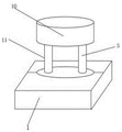
Fig. 1 is a schematic structural view of a base of a rapid calculation device for water pump flow and lift in a water supply and drainage design of a building according to an embodiment of the present invention;
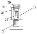
fig. 2 is a schematic overall structure diagram of a rapid calculation device for water pump flow and lift in building water supply and drainage design according to an embodiment of the present invention;
fig. 3 is a schematic structural diagram of a lifting device a of a rapid calculation apparatus for water pump flow rate and lift in a building water supply and drainage design according to an embodiment of the present invention;
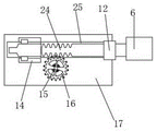
fig. 4 is a structural schematic diagram of the clamping device of the rapid calculation device for water pump flow and lift in the building water supply and drainage design of the embodiment of the present invention.
In the figure: 1. a base; 3. a clamping device; 4. mounting grooves; 5. a lifting device A; 6. a connecting rod; 7. a protection pad; 8. a ring plate is fixed; 9. a computing device; 10. a mounting seat; 11. a lifting device B; 12. fixing the shaft sleeve A; 14. a chute; 15. a motor A; 16. a gear; 17. a housing; 18. a motor B; 19. a sleeve; 20. a rotating shaft; 21. fixing the shaft sleeve B; 22. a threaded rod; 23. a threaded rod; 24. a rack bar; 25. the slot is moved.
Detailed Description
In order to make the objects, technical solutions and advantages of the present invention clearer, the present invention will be described in further detail with reference to the accompanying drawings, and it is obvious that the described embodiments are only some embodiments of the present invention, not all embodiments. Based on the embodiments in the present invention, all other embodiments obtained by a person skilled in the art without creative efforts belong to the protection scope of the present invention.
The following will describe in detail a rapid calculation device for water pump flow rate and lift in a building water supply and drainage design according to an embodiment of the present invention with reference to fig. 1 to 4.
Referring to fig. 1, 2, 3 and 4, a rapid calculation apparatus for water pump flow and lift in building water supply and drainage design provided by an embodiment of the present invention includes a base 1, a mounting groove 4 is formed around the base 1, a clamping device 3 is fixedly mounted inside the mounting groove 4, the clamping device 3 includes a housing 17, a motor a15, a gear 16, a rack 24, a moving chute 25, a fixed shaft sleeve a12, a connecting rod 6 and a sliding chute 14, a moving chute 25 is formed inside the housing 17, a sliding chute 14 is formed at the left side of the moving chute 25, the rack 24 is slidably mounted inside the moving chute 25, the left side of the rack 24 is slidably mounted inside the sliding chute 14, the outer side of the rack 24 is connected with the gear 16 in a meshing manner, the inner side of the gear 16 is rotatably connected with a power output end of a15, a fixed shaft sleeve a12 is fixedly mounted at the right side of the housing 17, and the rack bar 24 is inserted in the fixed shaft sleeve A12, the right side of the rack bar 24 is fixedly connected with a connecting rod 6, the left side of the connecting rod 6 is fixedly connected with a fastening ring sheet 8, the upper part of the fastening ring sheet 8 is detachably connected with one end of a lifting device A5, the other end of the lifting device A5 is fixedly installed in the mounting seat 10, the left side of the interior of the mounting seat 10 is fixedly provided with a lifting device B11, the lower part of the lifting device B11 is connected above a left clamping device 3, when in use, firstly, the computing device 9 is installed on the base 1, then the base 1 is installed on the outer side of the water pump, when the size needs to be adjusted, the motor A15 in the clamping device 3 installed in the interior of the mounting groove 4 of the base 1 is electrified through an external power supply, the motor A15 is electrified to work and rotate to drive the gear 16 on the outer side to rotate, and the gear 16 drives the rack bar 24 connected with the outer side in a meshing way to move, the left side of a toothed bar 24 slides in the chute 14, the left side of a toothed bar 16 slides in a fixed shaft sleeve A12, so that a connecting rod 6 on the right side of the toothed bar 16 is driven to jack up a locking ring sheet 8, clamping devices 3 on two sides of a base 1 act simultaneously to drive the locking ring sheet 8 to abut against the joint of a water pump, a protective pad 7 is embedded and connected in the locking ring sheet 8, the protective pad 7 is made of rubber and has good flexibility and skid resistance, the locking ring sheet 8 is ensured not to abut against a waterproof layer on the outer side of the water pump, the practicability of the device is improved, when in detection, firstly, an external power supply is used for electrifying the computing device 9, the computing device 9 is electrified for detection, when the detection depth needs to be adjusted, a motor B18 in a lifting device A5 and a lifting device B11 is electrified through the external power supply, the motor B18 works and rotates to drive a threaded rod 23 on the outer side to rotate and move along with a threaded sleeve rod 22 when the threaded rod 23 rotates, when screw loop bar 22 rotated, reciprocated inside fixed axle sleeve B221 inside sleeve 19, carried out altitude mixture control to the base 1 that the below is connected to install pivot 20 on screw loop bar 22 top, pivot 20 rotated along with screw loop bar 22, offset the turning force, prevent that base 1 from taking place to follow the commentaries on classics, thereby realized in time adjusting the degree of depth of calculation, improved the precision of calculation.
Referring to fig. 1, 2 and 3, the lifting device a5 includes a motor B18, a sleeve 19, a threaded rod 23, a fixed shaft sleeve B21, a rotating shaft 20 and a threaded rod 22, the sleeve 19 is fixedly mounted above the motor B18, the threaded rod 23 is rotatably connected to the power output end of the motor B18, the threaded rod 22 is connected to the outer side of the threaded rod 23 through a thread, the fixed shaft sleeve B21 is fixedly mounted above the sleeve 19, and the threaded rod 22 is inserted into the fixed shaft sleeve B21.
Referring to fig. 1, a computing device 9 is fixedly mounted on the left side of the base 1.
Referring to fig. 1, 2 and 3, the lifting device B11 has the same structure as the lifting device a 5.
Referring to fig. 3, a rotating shaft 20 is rotatably connected to the upper portion of the threaded rod 22.
Referring to fig. 1, a protection pad 7 is inlaid and connected on the inner side of the fastening ring sheet 8.
Referring to fig. 1, 3 and 4, the power input terminals of the motor a15 and the motor B18 are electrically connected to the power output terminal of the external power source.
The embodiment of the utility model provides a quick calculation equipment that is used for building water supply and drainage design water pump flow, lift, when using at first with computing device 9 ann at base 1, install base 1 in the water pump outside afterwards, when needs adjustment size, through the external power supply for base 1 inside installation 4 internally mounted clamping device 3 in the motor A15 circular telegram, motor A15 circular telegram work rotates the gear 16 rotation that drives the outside, gear 16 drives outside meshing connection's ratch 24 removal when rotating, ratch 24 left side slides in spout 14 inside, ratch 16 left side slides in fixed axle sleeve A12 inside, thereby drive connecting rod 6 jack-up of ratch 16 right side and lock ring piece 8, the clamping device 3 of base 1 both sides acts on simultaneously, drive lock ring piece 8 and support tightly the water pump junction, and lock ring piece 8 inside inlay and be connected with protection pad 7, protection pad 7 is the material is the rubber material, the anti-slip device has good flexibility and anti-slip performance, ensures that the fastening ring piece 8 can not damage a waterproof layer outside the water pump, improves the practicability of the device, when in detection, firstly, the computing device 9 is electrified through an external power supply, the computing device 9 is electrified for detection, when the detection depth needs to be adjusted, the lifting device A5 and the motor B18 inside the lifting device B11 are electrified through the external power supply, the motor B18 works and rotates to drive the threaded rod 23 outside to rotate inside the sleeve 19, the threaded rod 23 drives the threaded sleeve rod 22 outside to simultaneously rotate and move when rotating, the threaded sleeve rod 22 moves up and down inside the fixed sleeve B221 inside the sleeve 19, the height of the base 1 connected below is adjusted, the rotating shaft 20 is installed at the top end of the threaded sleeve rod 22, the rotating shaft 20 rotates along with the threaded sleeve rod 22 to offset the rotating force, and prevent the base 1 from rotating along, therefore, the calculation depth can be timely adjusted, and the calculation precision is improved.
It should be noted that the utility model relates to a quick calculating equipment for water pump flow and lift in building water supply and drainage design, which comprises a base 1, a clamping device 3, a mounting groove 4, a lifting device A5, a connecting rod 6, a protection pad 7, a fastening ring 8, a calculating device 9, a mounting seat 10, a lifting device B11, a fixed shaft sleeve A12, a sliding groove 14, a motor A15, a gear 16, a shell 17, a motor B18, a sleeve 19, a rotating shaft 20, a fixed shaft sleeve B21, a threaded sleeve rod 22, a threaded rod 23, a toothed rod 24 and a moving groove 25, wherein the electrical components are all prior art products, and are selected, installed and finished by technicians according to the needs of use, so as to ensure that each electrical appliance can work normally, and the components are universal standard components or components known by technicians in the field, and the structure and principle of the components can be known by the technicians or conventional experimental methods, the applicant does not make specific limitations herein.
It is apparent that those skilled in the art can make various changes and modifications to the embodiments of the present invention without departing from the spirit and scope of the embodiments of the present invention. Thus, if such modifications and variations of the embodiments of the present invention fall within the scope of the claims and their equivalents, the present invention is also intended to include such modifications and variations.
Claims (7)
1. The utility model provides a quick calculation equipment that is used for building water supply and drainage design normal water pump flow, lift, includes base (1), its characterized in that, base (1) has seted up mounting groove (4) all around, mounting groove (4) inside fixed mounting has clamping device (3), clamping device (3) include casing (17), motor A (15), gear (16), ratch (24), shifting chute (25), fixed axle sleeve A (12), connecting rod (6) and spout (14), shifting chute (25) have been seted up to the inside of casing (17), spout (14) begin to have on the left of shifting chute (25), the inside slidable mounting of shifting chute (25) has ratch (24), and the left side slidable mounting of ratch (24) is inside spout (14), the outside meshing of ratch (24) is connected with gear (16), the inside rotation of gear (16) is connected with the power take off end of motor A (15), the right side fixed mounting of casing (17) has fixed axle sleeve A (12), and ratch (24) are pegged graft in the inside of fixed axle sleeve A (12), the right side fixedly connected with connecting rod (6) of ratch (24), the left side fixedly connected with of connecting rod (6) is locked ring piece (8), the one end that is connected with hoisting device A (5) can be dismantled to the top of locking ring piece (8), the other end fixed mounting of hoisting device A (5) is in the inside of mount pad (10), the inside left side fixed mounting of mount pad (10) has hoisting device B (11), and the below of hoisting device B (11) is connected in the top of left side clamping device (3).
2. The rapid calculation device for the water pump flow and the lift in the building water supply and drainage design according to claim 1, wherein the lifting device A (5) comprises a motor B (18), a sleeve (19), a threaded rod (23), a fixed shaft sleeve B (21), a rotating shaft (20) and a threaded sleeve rod (22), the sleeve (19) is fixedly installed above the motor B (18), the threaded rod (23) is rotatably connected to a power output end of the motor B (18), the threaded sleeve rod (22) is connected to the outer side of the threaded rod (23) in a threaded manner, the fixed shaft sleeve B (21) is fixedly installed above the sleeve (19), and the threaded sleeve rod (22) is inserted into the fixed shaft sleeve B (21).
3. A rapid calculation device for water pump flow and lift in building water supply and drainage design according to claim 1, characterized in that a calculation device (9) is fixedly installed at the left side of the base (1).
4. A rapid calculation device for water pump flow and lift in building water supply and drainage design according to claim 1, characterized in that the structure of the lifting device B (11) is the same as that of the lifting device a (5).
5. A rapid calculation device for water pump flow and lift in building water supply and drainage design according to claim 2, characterized in that a rotating shaft (20) is rotatably connected above the threaded sleeve rod (22).
6. The rapid calculation equipment for water pump flow and lift in building water supply and drainage design according to claim 1 is characterized in that a protection pad (7) is embedded and connected to the inner side of the fastening ring sheet (8).
7. A rapid calculation device for water pump flow and lift in building water supply and drainage design according to claim 2, characterized in that the power input terminals of the motor a (15) and the motor B (18) are electrically connected with the power output terminal of the external power source.
Priority Applications (1)
| Application Number | Priority Date | Filing Date | Title |
|---|---|---|---|
| CN202022268679.6U CN214617097U (en) | 2020-10-13 | 2020-10-13 | Rapid calculating equipment for flow and lift of water pump in building water supply and drainage design |
Applications Claiming Priority (1)
| Application Number | Priority Date | Filing Date | Title |
|---|---|---|---|
| CN202022268679.6U CN214617097U (en) | 2020-10-13 | 2020-10-13 | Rapid calculating equipment for flow and lift of water pump in building water supply and drainage design |
Publications (1)
| Publication Number | Publication Date |
|---|---|
| CN214617097U true CN214617097U (en) | 2021-11-05 |
Family
ID=78375496
Family Applications (1)
| Application Number | Title | Priority Date | Filing Date |
|---|---|---|---|
| CN202022268679.6U Expired - Fee Related CN214617097U (en) | 2020-10-13 | 2020-10-13 | Rapid calculating equipment for flow and lift of water pump in building water supply and drainage design |
Country Status (1)
| Country | Link |
|---|---|
| CN (1) | CN214617097U (en) |
-
2020
- 2020-10-13 CN CN202022268679.6U patent/CN214617097U/en not_active Expired - Fee Related
Similar Documents
| Publication | Publication Date | Title |
|---|---|---|
| CN206726034U (en) | Integrated gate controller | |
| CN214617097U (en) | Rapid calculating equipment for flow and lift of water pump in building water supply and drainage design | |
| CN111594139A (en) | Oil well testing and equal pump filling stroke-number synchronous numerical control oil pumping method | |
| CN208604662U (en) | Novel water conservancy project Accrete clearing device | |
| CN210151908U (en) | Novel sewer desilting equipment | |
| CN215640294U (en) | Pit well head is administered and is used waste water detection reflux unit | |
| CN216329123U (en) | Cement agitating unit that pours after for building | |
| CN206409217U (en) | Intelligent variable parameter oil recovery energy-saving controller | |
| CN214235563U (en) | Soil leaching device for soil remediation | |
| CN107905972A (en) | A kind of portable water pumper based on solar power generation | |
| CN213204260U (en) | Civil engineering is with device of sunkening cord | |
| CN213923830U (en) | Pipe burying device for hydraulic and hydroelectric engineering | |
| CN210460501U (en) | Construction is high temperature design drilling equipment for foundation construction | |
| CN207093298U (en) | A kind of mining energy-saving emulsion power pack | |
| CN205895523U (en) | Ebb electricity energy storage pump water system | |
| CN206911192U (en) | Diving mixer | |
| CN209879293U (en) | Gate pump remote control device | |
| CN219715419U (en) | Urban river and lake overflow pollution on-line monitoring device | |
| CN218373704U (en) | Water conservancy water and electricity gate hoisting device | |
| CN211777585U (en) | Drainage flow control device for mine construction | |
| CN211143279U (en) | Integrated pump station with changeable volume, cleaning mechanism and flow guide mechanism | |
| CN210482516U (en) | Prevent prefabricated pump station of integration of silt pile up | |
| CN213141209U (en) | Novel drainage for municipal works device | |
| CN217175036U (en) | Mountain area water supply energy-saving pressurizing equipment | |
| CN216643585U (en) | Engineering intelligent monitoring device |
Legal Events
| Date | Code | Title | Description |
|---|---|---|---|
| GR01 | Patent grant | ||
| GR01 | Patent grant | ||
| CF01 | Termination of patent right due to non-payment of annual fee |
Granted publication date: 20211105 |
|
| CF01 | Termination of patent right due to non-payment of annual fee |