CN214614479U - Floor drain structure suitable for box at bottom of assembled bathroom - Google Patents
Floor drain structure suitable for box at bottom of assembled bathroom Download PDFInfo
- Publication number
- CN214614479U CN214614479U CN202023254485.7U CN202023254485U CN214614479U CN 214614479 U CN214614479 U CN 214614479U CN 202023254485 U CN202023254485 U CN 202023254485U CN 214614479 U CN214614479 U CN 214614479U
- Authority
- CN
- China
- Prior art keywords
- annular
- floor drain
- groove
- structure suitable
- bottom box
- Prior art date
- Legal status (The legal status is an assumption and is not a legal conclusion. Google has not performed a legal analysis and makes no representation as to the accuracy of the status listed.)
- Active
Links
Images


Landscapes
- Sink And Installation For Waste Water (AREA)
Abstract
The utility model provides a floor drain structure suitable for box at bottom of assembled bathroom relates to decoration design technical field, including the downcomer, first function piece, second function piece and floor drain spare, first function piece includes first annular dish and first annular post, first annular dish is provided with first annular groove, the internal thread that is provided with of first annular post, second function piece includes second annular dish and second annular post, second annular dish is provided with second annular groove and annular gasket, second annular post is provided with the external screw thread, box at the bottom of having in the basic unit of ground, decorative board and recess, floor drain spare includes the floor drain main part, the apron, filter screen and floor drain core. The utility model discloses simple structure, the assembled installation, connect stably, detachability is high, and convenient maintenance is looked over, and floor drain spare thickness is little, avoids being higher than the decorative board and leads to unable drainage, and floor drain lower part laminar arch can be connected with the water piping connection spare of various specifications, and offal performance is good, and drainage performance is good, and the risk of leaking is low.
Description
Technical Field
The utility model relates to the technical field of decoration design,
especially, the utility model relates to a floor drain structure suitable for box at bottom of assembled bathroom.
Background
The current decoration industry is developing towards the direction of industrialized modularized installation, generally speaking, the ground decoration is a decoration method commonly adopted in indoor design, and can increase the layering sense of indoor space and play a role in beautifying decoration.
The beauty of the ground is even more important, but the practicability is more important, the flat roof always has the common and frequent problem of water leakage, the water leakage not only affects the use of the building function, but also shortens the service life of the roof, so that the water drainage pipe and the waterproof structure need to be installed on the ground and the table board which have more water, including the areas such as toilets, kitchens, balconies, pools, basins and the like, and the application of the industrial assembly technology and the assembly type decoration in the decoration industry is more and more extensive, so that the construction time can be greatly saved, so that the assembly type installation of the waterproof structure is necessary, for example, Chinese patent invention CN106968404A relates to an assembly type roof drainage system and a construction method, which comprises a drainage component arranged together with the roof and a waterproof layer arranged together with the drainage pipe, wherein the waterproof layer comprises an impermeable layer arranged on the roof, the waterproof layer is sequentially provided with a coiled material waterproof layer, a heat insulation layer and a liner waterproof layer, the drainage assembly comprises an upper drainage pipe provided with an upper water inlet and a lower drainage pipe arranged on the periphery of the upper drainage pipe, a gap is reserved between the upper drainage pipe and the lower drainage pipe, the gap forms a lower water inlet, the upper water inlet is arranged together with the liner waterproof layer, and the lower water inlet is arranged together with the coiled material waterproof layer; for another example, chinese patent invention patent CN111962643A relates to an assembly type deodorization floor drain for building and its assembly method, including pre-buried box, floor drain closing cap, sealing bowl, transmission mechanism, discharge valve assembly, buoyancy device; the embedded box comprises a shell with an upward opening and a drain pipe, the upper end of the drain pipe is inserted into the bottom of the shell and is lower than the upper opening of the shell, and a water seal groove is formed in the radial outer space of the drain pipe in the shell, so that water in the water seal groove can overflow into the drain pipe; the floor drain sealing cover is arranged at the upper end of the shell; the opening of the sealing bowl faces downwards, and the sealing bowl is arranged above the drain pipe and is positioned in the shell; the buoyancy device is arranged in the water seal groove and is arranged at the lower end of the seal bowl; the discharge valve component is arranged in the drain pipe and is configured to enable the swinging blade to be in contact with the blocking plate so as to impact the swinging blade to drive the swinging impeller to rotate when water flows through and open a discharge port; the transmission mechanism is connected with the sealing bowl and can be connected with the swinging impeller in an opening and closing manner. The components are detachably connected, so that the assembly and the disassembly are simple, and the cleaning and the replacement of parts are convenient.
However, the above waterproof floor drain structure still has the following problems: the structure is still complicated, inconvenient dismantlement maintenance, and the floor drain is connected unstablely with the drain pipe upper end, and floor drain spare whole thickness is big, especially in bathroom dry area ceramic tile veneer department, can exceed the height of decorative board, can't effectual guide rivers get into the water pipe, can have rivers to the drain pipe outside, and all structures all use the waterproof area of adhesive bonding to carry out waterproofly, and easy ageing leads to leaking.
Therefore, in order to solve the above problems, it is necessary to design a reasonable and efficient floor drain structure suitable for the assembled bathroom bottom box.
SUMMERY OF THE UTILITY MODEL
An object of the utility model is to provide a simple structure, the assembled installation, the floor drain spare is stable with downcomer connection, and detachability is high, and convenient maintenance is looked over, and the floor drain spare is higher than the partial thickness of water pipe little, avoids being higher than the decorative board and leads to unable drainage, and floor drain lower part laminar arch can be connected with the water pipe connecting piece of various specifications, and it is good to launch the performance, and drainage performance is good, and the low floor drain structure who is applicable to box at the bottom of the assembled bathroom of the risk of leaking.
In order to achieve the above purpose, the utility model adopts the following technical scheme:
a floor drain structure suitable for an assembled bathroom bottom box comprises a sewer pipe arranged on a ground base layer, a first functional piece connected with the sewer pipe, a second functional piece connected with the first functional piece and a floor drain piece connected with the second functional piece, wherein the first functional piece comprises a first annular disc and a first annular column coaxially arranged with the first annular disc, one side, close to the first annular column, of the first annular disc is provided with a first annular groove which surrounds the outer side of the first annular column and is used for facilitating connection with the sewer pipe, the inner side of the first annular column is provided with internal threads, the second functional piece comprises a second annular disc and a second annular column coaxially arranged with the second annular disc, one side, close to the second annular column, of the second annular disc is provided with a second annular groove and an annular gasket used for clamping and connecting the second annular groove when the second functional piece is connected with the first functional piece, the outer side of the second annular column is provided with external threads matched with the internal threads, the ground base layer is paved with a bottom box and a veneer, at least one part of the bottom box is positioned between the first annular disc and the second annular disc, the ground base layer is also provided with a groove for facilitating the installation of the first annular disc, the floor drain piece comprises a floor drain main body, a cover plate, a filter screen and a floor drain core connected with the floor drain main body, the floor drain main body comprises a first main body and a second main body, the first main body comprises a first plate body and a first hole arranged on the first plate body, the second main body comprises a second plate body and a connecting cylinder connected with the second plate body, the second plate body extends downwards towards the connecting cylinder, the second plate body is provided with a circular outer groove and a circular inner groove arranged at the bottom of the circular outer groove, and the floor drain core comprises an annular plate and an annular cylinder connected with the annular plate, one end of the annular cylinder, which is far away from the annular plate, is provided with a first water discharging cylinder and a second water discharging cylinder which is eccentrically arranged with the first water discharging cylinder, and the height of the first plate body is not higher than that of the veneer.
As a preferred aspect of the present invention, the number of the first annular grooves is at least one.
As the utility model discloses a preferred, groove department is provided with and is used for fixing the adhesive of first function piece.
As the utility model discloses a preferred, the second annular disc outside is provided with the breach.
As a preferred aspect of the present invention, at least a portion of the notch is arc-shaped.
As the utility model discloses a preferred, annular gasket is the rubber spare.
As the utility model discloses a preferred, the quantity of circular outer tank is one at least.
As the utility model discloses a preferred, it is a plurality of circular outer tank is coaxial to be set up, and the external diameter is big circular outer tank sets up in that the external diameter is little circular outer tank outside.
As the utility model discloses an prefer, the quantity of filter screen is one at least.
As a preferred aspect of the present invention, the sum of the thicknesses of the first plate and the second plate is not greater than 10 mm.
As the utility model discloses a preferred, be provided with the fly leaf between first section of thick bamboo and the second section of thick bamboo that drains, the fly leaf sets up for the slope, the angle that the line of fly leaf and first section of thick bamboo axle center and second section of thick bamboo axle center formed is less than 90.
The utility model relates to a floor drain structure suitable for box at bottom of assembled bathroom beneficial effect lies in: simple structure, the assembled installation, the floor drain spare is connected with the downcomer stably, and detachability is high, and convenient maintenance is looked over, and the part thickness that the floor drain spare is higher than the water pipe is little, avoids being higher than the decorative board and leads to unable drainage, and floor drain lower part laminar arch can be connected with the water pipe connecting piece of various specifications, and the offal performance is good, and drainage performance is good, and the risk of leaking is low.
Drawings
Fig. 1 is a schematic overall structure diagram of an embodiment of a floor drain structure suitable for an assembled bathroom bottom box according to the present invention;
fig. 2 is an assembly diagram of the overall structure of an embodiment of the floor drain structure suitable for the assembled bathroom bottom box of the present invention;
fig. 3 is a schematic perspective view of a first functional member in an embodiment of a floor drain structure suitable for an assembled bathroom bottom box according to the present invention;
fig. 4 is a schematic perspective view of a second functional member in an embodiment of a floor drain structure for an assembled bathroom bottom box according to the present invention;
fig. 5 is an assembly view of a floor drain suitable for an embodiment of a floor drain structure of an assembled sanitary bottom box according to the present invention;
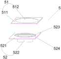
fig. 6 is an assembly diagram of a floor drain main body according to an embodiment of the floor drain structure of the assembled sanitary bottom box of the present invention;
fig. 7 is a schematic cross-sectional view of a floor drain suitable for an embodiment of a floor drain structure of an assembled bathroom bottom box according to the present invention;
FIG. 8 is a schematic view of the whole structure of another embodiment of the floor drain structure suitable for the bottom box of the assembled bathroom
In the figure: 1. downcomer, 2, first function, 21, first annular disc, 211, first annular groove, 22, first annular post, 221, internal thread, 3, second function, 31, second annular disc, 311, second annular groove, 312, annular gasket, 313, gap, 32, second annular post, 321, external thread, 4, ground base, 41, bottom box, 42, veneer, 43, groove, 5, floor drain body, 51, first body, 511, first plate body, 512, first hole, 52, second body, 521, second plate body, 522, connecting cylinder, 523, circular outer groove, 524, circular inner groove, 6, floor drain core, 61, annular plate, 62, annular cylinder, 63, first downcomer, 631, movable plate, 64, second downcomer, 7, cover plate, 8, filter screen.
Detailed Description
The following are specific embodiments of the present invention, and the technical solutions of the present invention are further described, but the present invention is not limited to these embodiments.
Various exemplary embodiments of the present invention will now be described in detail with reference to the accompanying drawings. It should be noted that: the relative arrangement of modules and steps and the steps set forth in these embodiments do not limit the scope of the present invention unless specifically stated otherwise.
Meanwhile, it should be understood that the flows in the drawings are not merely performed individually for convenience of description, but a plurality of steps are performed alternately with each other.
In the description of the present invention, it should be noted that the terms "center", "upper", "lower", "left", "right", "vertical", "horizontal", "inner", "outer", etc. indicate the position or positional relationship based on the position or positional relationship shown in the drawings, or the position or positional relationship which the product of the present invention is usually placed when in use, and are only for convenience of description of the present invention and simplification of description, but do not indicate or imply that the device or element referred to must have a specific position, be constructed and operated in a specific orientation, and therefore, should not be construed as limiting the present invention. Furthermore, the terms "first," "second," and the like are used merely to distinguish one description from another, and are not to be construed as indicating or implying relative importance.
The following description of at least one exemplary embodiment is merely illustrative in nature and is in no way intended to limit the invention, its application, or uses.
Techniques, methods, and systems known to those of ordinary skill in the relevant art may not be discussed in detail, but are intended to be part of the specification where appropriate.
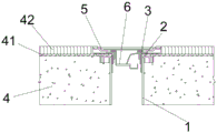
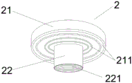
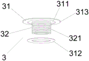
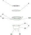
The first embodiment is as follows: as shown in fig. 1 to 7, which are only one embodiment of the present invention, a floor drain structure suitable for an assembled sanitary bottom box comprises a downcomer 1 installed on a ground substrate 4, a first functional member 2 connected with the downcomer 1, a second functional member 3 connected with the first functional member 2, and a floor drain connected with the second functional member 3, wherein the first functional member 2 comprises a first annular disc 21 and a first annular column 22 coaxially arranged with the first annular disc 21, a first annular groove 211 surrounding the first annular column 22 at one side of the first annular disc 21 for facilitating connection with the downcomer 1 is arranged at the outer side of the first annular column 22, an internal thread 221 is arranged at the inner side of the first annular column 22, the second functional member 3 comprises a second annular disc 31 and a second annular column 32 coaxially arranged with the second annular disc 31, a second annular groove 311 and an annular gasket 312 used for being clamped into the second annular groove 311 when the second functional element 3 is connected with the first functional element 2 are arranged on one side of the second annular disc 31 close to the second annular column 32, an external thread 321 matched with the internal thread 221 is arranged on the outer side of the second annular column 32, a bottom box 41 and a veneer 42 are paved on the ground base layer 4, at least one part of the bottom box 41 is positioned between the first annular disc 21 and the second annular disc 31, the ground base layer 4 is further provided with a groove 43 used for facilitating installation of the first annular disc 21, the floor drain element comprises a floor drain main body 5, a cover plate 7, a filter screen 8 and a floor drain core 6 connected with the floor drain main body 5, the floor drain main body 5 comprises a first main body 51 and a second main body 52, the first main body 51 comprises a first plate body 511 and a first hole 512 arranged on the first plate body 511, the second main body 52 comprises a second plate body 521 and a connecting cylinder 522 connected with the second plate body 521, the second plate body 521 is arranged in a downward-concave extending mode in the direction of the connecting cylinder 522, a circular outer groove 523 and a circular inner groove 524 arranged at the bottom of the circular outer groove 523 are arranged on the second plate body 521, the floor drain core 6 comprises an annular plate 61 and an annular cylinder 62 connected with the annular plate 61, a first lower water cylinder 63 and a second lower water cylinder 64 eccentrically arranged with the first lower water cylinder 63 are arranged at one end, far away from the annular plate 61, of the annular cylinder 62, and the height of the first plate body 511 is not higher than that of the veneer 42.
The utility model discloses in, first function piece 2 is connected to on the downcomer 1 of ground basic unit 4 and buries the below at end box 41, and the detachable top that is connected to first function piece 2 and lies in end box 41 that is connected to of second function piece 3 is last to lay decorative board 42 around the 3 outsides of second function piece on end box 41 can, can set up ground leakage piece on second function piece 3 at last.
The first functional part 2 comprises a first annular disc 21 and a first annular column 22 coaxially arranged with the first annular disc 21, a first annular groove 211 surrounding the first annular column 22 and used for conveniently connecting with the downcomer 1 is arranged on one side, close to the first annular column 22, of the first annular disc 21, when the first annular disc 21 is installed, the first annular disc 21 is arranged above the first annular column 22, the outer diameter of the first annular disc 21 is larger than that of the first annular column 22, the first annular column 22 is inserted into the downcomer 1, the lower surface of the first annular disc 21 is connected with the upper end of the downcomer 1, and the lower surface of the first annular disc 21 is provided with the first annular groove 211 matched with the side wall of the downcomer 1, so that the upper end of the downcomer 1 is inserted into the first annular groove 211.
Here, the first annular disc 21 and the first annular column 22 have the same inner diameter.
The second function piece 3 comprises a second annular disc 31 and a second annular column 32 coaxially arranged with the second annular disc 31, wherein the second annular disc 31 is close to one side of the second annular column 32, a second annular groove 311 is arranged on one side of the second annular column 31, and the second annular column is used for clamping the second function piece 3 to an annular gasket 312 in the second annular groove 311 when the second function piece is connected with the first function piece 2. When the annular gasket is installed, the second annular disc 31 is arranged above the second annular column 32, the outer diameter of the second annular disc 31 is larger than that of the second annular column 32, the second annular column 32 is inserted into the first annular column 22, but the lower surface of the second annular disc 31 is in contact with the upper surface of the first annular disc 21, in order to prevent water leakage between the lower surface of the second annular disc 31 and the upper surface of the first annular disc 21, a second annular groove 311 which surrounds the second annular column 32 for one circle is arranged on the lower side of the second annular disc 31, and the annular gasket 312 can just be filled into the second annular groove 311.
Here, the inner diameters of the second annular disk 31 and the second annular column 32 are the same, and the inner diameter of the annular gasket 312 is equal to the outer diameter of the second annular column 32, and the thickness of the annular gasket 312 is not less than the depth of the second annular groove 311.
Then, the second functional part 3 is connected with the second functional part 2, the inner side of the first annular column 22 is provided with an internal thread 221, the outer side of the second annular column 32 is provided with an external thread 321 matched with the internal thread 221, and the outer diameter of the second annular column 32 is the same as the inner diameter of the first annular column 22. The second annular column 32 is threadedly inserted and mounted downwardly into the first functional member 2 by the external thread 321 of the second annular column 32 being threadedly coupled with the internal thread 221 of the first annular column 22.
The ground base layer 4 is paved with a bottom box 41 and a veneer 42, at least one part of the bottom box 41 is positioned between the first annular disc 21 and the second annular disc 31, the thickness of the veneer 42 is not less than that of the second annular disc 31, the ground base layer 4 is also provided with a groove 43 for facilitating the installation of the first annular disc 21, here, the bottom box 41 is paved after the installation of the first functional element 2 and before the installation of the second functional element 3, the veneer 42 is paved after the installation of the second functional element 3, and the height of the veneer 42 can be equal to or greater than that of the second annular disc 31. Of course, before the first functional element 2 is installed, in order to make the first annular disc 21 flush with the upper surface of the ground substrate 4 for easy installation of the bottom case 41, a groove 43 with the depth equal to the thickness of the first annular disc 21 needs to be provided on the ground substrate 4 for easy installation of the first annular disc 21.
The floor drain main body 5 comprises a first main body 51 and a second main body 52, wherein the first main body 51 comprises a first plate body 511 and a first hole 512 arranged on the first plate body 511, the second main body 52 comprises a second plate body 521 and a connecting cylinder 522 connected with the second plate body 521, the second plate body 521 is arranged in a downward-concave extending manner towards the connecting cylinder 522, a circular outer groove 523 and a circular inner groove 524 arranged at the bottom of the circular outer groove 523 are arranged on the second plate body 521, the second plate body 521 is arranged in a downward-concave extending manner towards the connecting cylinder 522, namely the second plate body 521 is convex towards the direction far away from the first plate body 511, but not a solid convex but a hollow convex, when seen in the direction of the connecting cylinder 522, the concave groove is formed, and comprises the circular outer groove 523 close to the direction of the first plate body 511 and the circular inner groove 524 close to the direction of the connecting cylinder 522, the connecting tube 522 is disposed on a layer of the second board 521 away from the first board 511.
Here, the first plate 511 has the same size as the second plate 521.
The diameter of the first hole 512 is larger than the inner diameter of the circular outer groove 523, the inner diameter of the circular outer groove 523 is larger than the inner diameter of the circular inner groove 524, so that the protrusion of the second plate 521 in the direction away from the first plate 511 is a step-shaped protrusion, the farther the protrusion is, the smaller the outer diameter is, the convenience is brought to inserting into the hole in the middle of the second annular disc 31, and the outer diameter of the protrusion of one layer is always just matched with the hole in the middle of the second annular disc 31, so that the floor drain main body 5 has better structural stability and can be suitable for installing various sewer pipes.
The floor drain core 6 comprises an annular plate 61 and an annular cylinder 62 connected with the annular plate 61, one end, far away from the annular plate 61, of the annular cylinder 62 is provided with a first water drainage cylinder 63 and a second water drainage cylinder 64 eccentrically arranged with the first water drainage cylinder 63, and the second water drainage cylinder 64 and the first water drainage cylinder 63 are eccentrically arranged, so that the drainage performance is better.
The outer diameter of the cover plate 7 is the same as the inner diameter of the first hole 512, the outer diameter of the screen 8 is the same as the inner diameter of the circular outer groove 523, the outer diameter of the annular plate 61 is the same as the inner diameter of the circular inner groove 524, and the outer diameter of the annular cylinder 62 is the same as the inner diameter of the connector cylinder 522. The floor drain core 6 is first attached to the second body 52 of the floor drain body 5 such that the annular plate 61 is positioned in the circular inner groove 524 and the annular cylinder 62 is inserted into the connecting cylinder 522, then the strainer 8 is installed in the circular outer groove 523, then the first body 51 is attached to the second body 52, and finally the cover plate 7 is installed in the first hole 511.
Moreover, the part of the whole floor drain piece protruding out of the sewer pipe connecting piece is the first plate body 511 and the second plate body 521, and the sum of the thicknesses of the first plate body 511 and the second plate body 521 is not more than 10mm, so that the installation height of the whole floor drain piece is less than 10mm and less than the thickness of a common veneer, and the floor drain structure cannot be higher than the veneer to cause incapability of draining water.
In a word, when in installation, the groove 43 is arranged at the position where the downcomer 1 is installed on the ground base layer 4; mounting the first function 2 to the groove 43 such that the first annular column 22 of the first function 2 extends downwardly into the downcomer 1 and the upper end of the downcomer 1 extends just into the first annular groove 211 on the underside of the first annular disc 21; then laying a bottom box 41 above the first annular disc 21; an annular gasket 312 is clamped in a second annular groove 311 on the lower side of the second annular disc 31 of the second functional part 3, and the second annular column 32 is downwards inserted and installed in the first functional part 2 through the threaded connection of the external thread 321 of the second annular column 32 and the internal thread 221 of the first annular column 22; then, the decorative panels 42 are laid on the bottom box 41 around the outer side of the second annular disc 31, and finally, the assembled floor drain is installed on the second annular disc 31 and located between the decorative panels 42, wherein the overall height of the floor drain (the highest part is the first plate body 511) is lower than the height of the decorative panels 42.
When needing to be maintained and checked, the condition of the bottom box 41 and the ground base layer 4 can be checked and maintained only by taking out the floor drain part and reversely rotating the second functional part 3 to separate from the first functional part 2.
The utility model relates to a floor drain structure suitable for box at bottom of assembled bathroom simple structure, the assembled installation, floor drain spare and downcomer are connected stably, and detachability is high, and convenient maintenance is looked over, and floor drain spare is higher than the partial thickness of water pipe little, avoids being higher than the decorative board and leads to unable drainage, and floor drain lower part laminar arch, can be connected with the water pipe connection spare of various specifications, and the offal performance is good, and drainage performance is good, and the risk of leaking is low.
Second embodiment, as shown in fig. 1 to 8, which is only one embodiment of the present invention, on the basis of the first embodiment, the present invention provides a floor drain structure suitable for an assembled bathroom bottom box, wherein the number of the first annular groove 211 is at least one, and generally, the downcomer 1 has several through specifications, such as 50 downcomers or 75 downcomers, then a plurality of first annular grooves 211 are provided on the lower surface of the first annular disc 21 to match the insertion and installation of the downcomers 1 with various specifications, so that the first functional element 2 can be installed in cooperation with the downcomers 1 with various specifications, as shown in fig. 1 and 8.
Then, the groove 43 is provided with an adhesive for fixing the first functional component 2, and since the second functional component 3 is to rotate with the first functional component 2, the first functional component 2 needs to be fixed in order to facilitate the rotation of the second functional component 3, and then after the first functional component 2 is installed, the first functional component 2 is fixed to the ground substrate 4 through the adhesive.
Similarly, a film adhesive is applied to the second annular disc to facilitate adhering the floor drain when the floor drain is installed.
Moreover, the notch 313 is arranged on the outer side of the second annular disc 31, the second annular column 32 is inserted into the first functional part 2 in a downward threaded manner by clamping the notch 313 of the second annular disc 31, similarly, the second annular column 32 can be screwed out of the first functional part 2 in an upward threaded manner by clamping the notch 313 of the second annular disc 31, and at least a part of the notch 313 is arc-shaped, so that the maintenance personnel can conveniently screw the notch 313 manually.
And, annular gasket 312 is the rubber spare, plays the effect of flexible stagnant water packing ring, and waterproof performance is better.
The number of the circular outer grooves 523 is at least one, the circular outer grooves 523 are coaxially arranged, and the circular outer groove 523 with a large outer diameter is arranged outside the circular outer groove 523 with a small outer diameter.
So can increase the bellied ladder number of second plate body 521, can be provided with the circular outer groove 523 that the multilayer is convenient for set up filter screen 8 two, like this, filter screen 8's quantity is one at least, all can be provided with a filter screen 8 on the circular outer groove 523 of each layer, sets up filter screen 8's quantity according to the filter effect demand, and the floor drain effect is better.
The length of the annular cylinder 62 is not less than the length of the connecting cylinder 522, and the annular cylinder 62 extends into the downcomer 1 or the second functional element 3 through the lower end of the connecting cylinder 522.
The cover plate 7 and the second body 52 are both stamped parts. The cover plate part is obtained by stamping and pattern laser cutting, the second main body 52 forms a stepped multi-layer convex structure by multiple stamping, of course, filter holes are arranged on the filter screen 8, and the number of the filter holes is at least one.
Finally, a movable plate 631 is arranged between the first launching tube 63 and the second launching tube 64, the movable plate 631 is obliquely arranged, an angle formed by the movable plate 631 and a connecting line of the axle center of the first launching tube 63 and the axle center of the second launching tube 64 is smaller than 90 degrees, so that sewage guided into the first launching tube 63 is obliquely guided into the second launching tube 64, and more efficient drainage is facilitated.
An embodiment three, the utility model provides a method for installing be applicable to the floor drain structure of box at bottom of assembled bathroom still in all above-mentioned embodiments, include following step:
s1: arranging a groove at the position of a sewer pipe arranged on the ground base layer;
s2: installing the first functional part to the groove, so that the first annular column of the first functional part extends downwards into the sewer pipe, and the upper end of the sewer pipe just extends into the first annular groove on the lower side of the first annular disc;
s3: laying a bottom box above the first annular disc;
s4: an annular gasket is clamped in a second annular groove in the lower side of a second annular disc of the second functional piece, and the second annular column is inserted into the first functional piece in a downward threaded manner by performing threaded connection on the external thread of the second annular column and the internal thread of the first annular column;
s5: paving a veneer on the bottom box around the outer side of the second annular disc;
s6: inserting the floor drain core into the floor drain main body, and installing a filter screen and a cover plate to form an integral floor drain piece;
s7: and installing the floor drain piece on the second annular disc, so that the first lower water cylinder and the second lower water cylinder are inserted into the second annular column, and the height of the first plate body is not higher than that of the veneer.
After the step S2 is performed, the first functional element is fixed by using an adhesive after the first functional element is mounted in the groove.
Step S4 is executed to screw-insert the second annular post downward into the first functional member by sandwiching the notch of the second annular disk.
Before performing step S7, an adhesive is coated on the second annular disc for facilitating the adhesion of the floor drain.
The utility model relates to a floor drain suitable for box at bottom of assembled bathroom simple structure, the assembled installation, floor drain spare and downcomer are connected stably, and detachability is high, and convenient maintenance is looked over, and floor drain spare is higher than the partial thickness of water pipe little, avoids being higher than the decorative board and leads to unable drainage, and floor drain lower part laminar arch, can be connected with the water pipe connecting piece of various specifications, and offal performance is good, and drainage performance is good, and the risk of leaking is low.
The present invention is not limited to the above-described specific embodiments, and various modifications and changes are possible. Any modification, equivalent replacement, improvement and the like made to the above embodiments according to the technical spirit of the present invention should be included in the scope of protection of the present invention.
Claims (10)
1. The utility model provides a floor drain structure suitable for box at bottom of assembled bathroom which characterized in that: the floor drain comprises a sewer pipe (1) arranged on a ground base layer (4), a first functional part (2) connected with the sewer pipe (1), a second functional part (3) connected with the first functional part (2) and a floor drain part connected with the second functional part (3), wherein the first functional part (2) comprises a first annular disc (21) and a first annular column (22) coaxially arranged with the first annular disc (21), one side of the first annular disc (21) close to the first annular column (22) is provided with a first annular groove (211) which surrounds the outer side of the first annular column (22) and is used for being conveniently connected with the sewer pipe (1), the inner side of the first annular column (22) is provided with an internal thread (221), the second functional part (3) comprises a second annular disc (31) and a second annular column (32) coaxially arranged with the second annular disc (31), a second annular groove (311) and an annular gasket (312) used for being clamped into the second annular groove (311) when the second functional piece (3) is connected with the first functional piece (2) are arranged on one side, close to the second annular column (32), of the second annular disc (31), an external thread (321) matched with the internal thread (221) is arranged on the outer side of the second annular column (32), a bottom box (41) and a veneer board (42) are laid on the ground base layer (4), at least one part of the bottom box (41) is located between the first annular disc (21) and the second annular disc (31), the ground base layer (4) is further provided with a groove (43) used for facilitating installation of the first annular disc (21), and the ground leakage piece comprises a floor drain main body (5), a cover plate (7), a filter screen (8) and a ground leakage core (6) connected with the floor drain main body (5), the floor drain main body (5) comprises a first main body (51) and a second main body (52), the first main body (51) comprises a first plate body (511) and a first hole (512) formed in the first plate body (511), the second main body (52) comprises a second plate body (521) and a connecting cylinder (522) connected with the second plate body (521), the second plate body (521) is arranged in a downward concave extending mode in the direction of the connecting cylinder (522), a circular outer groove (523) and a circular inner groove (524) formed in the bottom of the circular outer groove (523) are arranged on the second plate body (521), the floor drain core (6) comprises an annular plate (61) and an annular cylinder (62) connected with the annular plate (61), a first lower water cylinder (63) and a second lower water cylinder (64) eccentrically arranged with the first lower water cylinder (63) are arranged at one end, far away from the annular plate (61), of the annular cylinder (62), the height of the first plate body (511) is not higher than that of the veneer (42).
2. The floor drain structure suitable for the assembled bathroom bottom box of claim 1, wherein: the number of the first annular grooves (211) is at least one.
3. The floor drain structure suitable for the assembled bathroom bottom box of claim 1, wherein: and an adhesive for fixing the first functional part (2) is arranged at the groove (43).
4. The floor drain structure suitable for the assembled bathroom bottom box of claim 1, wherein: and a notch (313) is arranged on the outer side of the second annular disc (31).
5. The floor drain structure suitable for the assembled bathroom bottom box of claim 4, wherein: at least a portion of the notch (313) is arcuate.
6. The floor drain structure suitable for the assembled bathroom bottom box of claim 1, wherein: the annular gasket (312) is a rubber piece.
7. The floor drain structure suitable for the assembled bathroom bottom box of claim 1, wherein: the number of the circular outer grooves (523) is at least one, the circular outer grooves (523) are coaxially arranged, and the circular outer groove (523) with the large outer diameter is arranged on the outer side of the circular outer groove (523) with the small outer diameter.
8. The floor drain structure suitable for the assembled bathroom bottom box of claim 7, wherein: the number of the filter screens (8) is at least one.
9. The floor drain structure suitable for the assembled bathroom bottom box of claim 1, wherein: the sum of the thicknesses of the first plate body (511) and the second plate body (521) is not more than 10 mm.
10. The floor drain structure suitable for the assembled bathroom bottom box of claim 1, wherein: a movable plate (631) is arranged between the first launching tube (63) and the second launching tube (64).
Priority Applications (1)
| Application Number | Priority Date | Filing Date | Title |
|---|---|---|---|
| CN202023254485.7U CN214614479U (en) | 2020-12-30 | 2020-12-30 | Floor drain structure suitable for box at bottom of assembled bathroom |
Applications Claiming Priority (1)
| Application Number | Priority Date | Filing Date | Title |
|---|---|---|---|
| CN202023254485.7U CN214614479U (en) | 2020-12-30 | 2020-12-30 | Floor drain structure suitable for box at bottom of assembled bathroom |
Publications (1)
| Publication Number | Publication Date |
|---|---|
| CN214614479U true CN214614479U (en) | 2021-11-05 |
Family
ID=78433482
Family Applications (1)
| Application Number | Title | Priority Date | Filing Date |
|---|---|---|---|
| CN202023254485.7U Active CN214614479U (en) | 2020-12-30 | 2020-12-30 | Floor drain structure suitable for box at bottom of assembled bathroom |
Country Status (1)
| Country | Link |
|---|---|
| CN (1) | CN214614479U (en) |
Cited By (1)
| Publication number | Priority date | Publication date | Assignee | Title |
|---|---|---|---|---|
| CN112554317A (en) * | 2020-12-30 | 2021-03-26 | 浙江亚厦装饰股份有限公司 | Floor drain structure suitable for assembly type bathroom bottom box and installation method |
-
2020
- 2020-12-30 CN CN202023254485.7U patent/CN214614479U/en active Active
Cited By (1)
| Publication number | Priority date | Publication date | Assignee | Title |
|---|---|---|---|---|
| CN112554317A (en) * | 2020-12-30 | 2021-03-26 | 浙江亚厦装饰股份有限公司 | Floor drain structure suitable for assembly type bathroom bottom box and installation method |
Similar Documents
| Publication | Publication Date | Title |
|---|---|---|
| JP5802679B2 (en) | Sealing flush toilet flange | |
| US8474068B2 (en) | Trench shower drain | |
| CN112554317A (en) | Floor drain structure suitable for assembly type bathroom bottom box and installation method | |
| CN214614479U (en) | Floor drain structure suitable for box at bottom of assembled bathroom | |
| CN104847134A (en) | Integrated drainage unit bathroom waterproof base plate | |
| CN214614383U (en) | Waterproof construction of assembled installation | |
| CN112554318A (en) | Hidden floor drain structure suitable for assembly type toilet and installation method | |
| CN112095720A (en) | Drainage sleeve mounting assembly and mounting method | |
| CN204676934U (en) | A kind of integrated draining integral bathroom water-proof chassis | |
| JP5315208B2 (en) | Drainage container | |
| CN106869289B (en) | Building same-layer drainage floor drain | |
| HUT73599A (en) | Outlet component to be mounted in concrete floors in particular | |
| CN213773707U (en) | Side floor drain device for drainage of assembled toilet without lowering floor on same floor | |
| CN213773708U (en) | Wall side floor drain installation watertight fittings | |
| CN214614481U (en) | Hidden floor drain structure suitable for assembled bathroom | |
| CN213653634U (en) | Drainage sleeve installation assembly | |
| CN110043737B (en) | Pre-buried type cyclone joint with water leakage connector | |
| CN112196028A (en) | Blowdown structure, bathroom chassis and pin-connected panel bathroom | |
| CN112554284A (en) | Assembled installation waterproof structure and installation method | |
| CN218911687U (en) | Can dismantle drainage pre-buried device | |
| CN219240786U (en) | Assembled double drainage floor drain suitable for overhead ground | |
| CN213653635U (en) | Anti-overflow structure and drainage riser device | |
| CN220202908U (en) | Floor drain of integral bathroom | |
| CN220133062U (en) | Drainage structure for ceramic tile integrated waterproof bottom box | |
| CN218264226U (en) | Horizontal floor drain suitable for assembled integral bathroom |
Legal Events
| Date | Code | Title | Description |
|---|---|---|---|
| GR01 | Patent grant | ||
| GR01 | Patent grant |